


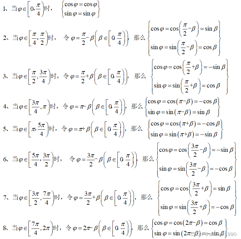
在前两篇文章中,设置的输入角度范围分别是[0,2*pi)和[0,pi/2)。但根据三角函数公式,其实我们还可以将[0,2*pi)分成8段,这样就能将输入角度范围继续缩小到[0,pi/4)了。
1、修改matlab代码
%%%%%%%%%%%%%%%%%%%%%%%%%%%%%%%%%%%%%%%%%%%%%%%%%%%%%%%%%%%%%%%%%%%%%%%%%%%%%%%%%%%%%%%%%%%%%%%%%%%%%%%%%
%% Zheng Wei, 2022/12/06
%%
%% 输入角度范围:[0,pi/4); 输入数据量化位数:10bit;
%% 输出结果范围:[0,1];    输出数据量化位数:16bit;
%%%%%%%%%%%%%%%%%%%%%%%%%%%%%%%%%%%%%%%%%%%%%%%%%%%%%%%%%%%%%%%%%%%%%%%%%%%%%%%%%%%%%%%%%%%%%%%%%%%%%%%%%

clc;        % 清理命令行
close all;  % 关闭所有图形窗口
clear all;  % 清理所有工作区变量


%%%%%%%%%%%%%%%%%%%%%%%%%%%%%%%%%%%%%%%%%%%%%%%%%%%%%%%%%%%%%%%%%%%
%% 参数定义
%%%%%%%%%%%%%%%%%%%%%%%%%%%%%%%%%%%%%%%%%%%%%%%%%%%%%%%%%%%%%%%%%%%
in_quantify_bit = 10;        % 输入数据量化位数(无符号数)
alpha = 0:(pi/4/2^in_quantify_bit):(pi/4-pi/4/2^in_quantify_bit);  % 弧度

out_quantify_bit = 16;       % 输出数据量化位数(有符号数)


%%%%%%%%%%%%%%%%%%%%%%%%%%%%%%%%%%%%%%%%%%%%%%%%%%%%%%%%%%%%%%%%%%%
%% 获取三角函数值
%%%%%%%%%%%%%%%%%%%%%%%%%%%%%%%%%%%%%%%%%%%%%%%%%%%%%%%%%%%%%%%%%%%
cos_alpha = cos(alpha);  % 获得cos函数值
sin_alpha = sin(alpha);  % 获得sin函数值

cos_alpha_q = round(cos_alpha *(2^(out_quantify_bit-1)-1));  % 16bit量化
sin_alpha_q = round(sin_alpha *(2^(out_quantify_bit-1)-1));  % 16bit量化

% figure(1); subplot(2,1,1);plot(alpha,cos_alpha);subplot(2,1,2);plot(alpha,cos_alpha_q);
% figure(2); subplot(2,1,1);plot(alpha,sin_alpha);subplot(2,1,2);plot(alpha,sin_alpha_q);


%%%%%%%%%%%%%%%%%%%%%%%%%%%%%%%%%%%%%%%%%%%%%%%%%%%%%%%%%%%%%%%%%%%
%% 生成coe文件,第一行定义数据格式, 16代表ROM的数据格式为16进制。
%% 高16bit代表sin值,低16bit代表cos值,各自最高的1bit是符号位。
%%%%%%%%%%%%%%%%%%%%%%%%%%%%%%%%%%%%%%%%%%%%%%%%%%%%%%%%%%%%%%%%%%%

% 因为都是正数,所以不需要取补码
% for i = 1:1:(2^in_quantify_bit)
%     if (cos_alpha_q(i)<0)
%        cos_alpha_q(i) = cos_alpha_q(i) + 2^(out_quantify_bit); % 负数用补码表示
%     else
%        cos_alpha_q(i) = cos_alpha_q(i); % 正数的补码为原码
%     end
%
%     if (sin_alpha_q(i)<0)
%        sin_alpha_q(i) = sin_alpha_q(i) + 2^(out_quantify_bit); % 负数用补码表示
%     else
%        sin_alpha_q(i) = sin_alpha_q(i); % 正数的补码为原码
%     end
% end

cos_alpha_q = dec2hex(cos_alpha_q);
sin_alpha_q = dec2hex(sin_alpha_q);

% 将cos和sin拼接为32bit(各自16bit),此数据输出到FPGA
fid=fopen('cos_sin_lut_3.coe','wt');
fprintf( fid, 'MEMORY_INITIALIZATION_RADIX = 16;\n');
fprintf( fid, 'MEMORY_INITIALIZATION_VECTOR =\n');

for i = 1:1:(2^in_quantify_bit)
    s=strcat(sin_alpha_q(i,1),sin_alpha_q(i,2),sin_alpha_q(i,3),sin_alpha_q(i,4),cos_alpha_q(i,1),cos_alpha_q(i,2),cos_alpha_q(i,3),cos_alpha_q(i,4));
    fprintf(fid,'%c%c%c%c%c%c%c%c',s);
    if (i < 2^in_quantify_bit)
        fprintf(fid,',\n');
    else
        fprintf(fid,';\n');  % 分号(;) 结束标志位
    end
end
fclose(fid);
2、将重新生成的coe文件写入ROM核中
3、通过查表得到角度所对应的正弦值和余弦值
/*----------------------------------------------------------------------
Author: Zheng Wei
Date: 2022-12-06
Version: 1.0
Description: It is a cos_sin_lut_3 testbench.
-----------------------------------------------------------------------*/
`timescale 1ns / 1ps
module tb;
reg i_sys_clk ;
reg i_sys_rst ;
reg [12:0] r_rom_phase ;
reg [12:0] r_rom_phase_ff ;
reg [12:0] r_rom_phase_2ff ;
reg [12:0] r_rom_phase_3ff ;
reg [09:0] r_rom_addr ;
wire [15:0] w_cos_rom_val ; // ROM readout value [0, pi/4)
wire [15:0] w_sin_rom_val ; // ROM readout value [0, pi/4)
reg [16:0] r_cos_val ; // transform output value[0, 2*pi)
reg [16:0] r_sin_val ; // transform output value[0, 2*pi)
wire [15:0] o_cos_val ; // final output value, drop the least 1bit
wire [15:0] o_sin_val ; // final output value, drop the least 1bit
// clock generate module
parameter period = 6.67; // 150MHz
initial begin
i_sys_clk = 1'b0;
forever #(period/2) i_sys_clk = ~i_sys_clk;
end
//-------------------------------------------------------------------
// system initialization
task task_sysinit;
begin
r_rom_phase = 12'd0;
end
endtask
// system reset
task task_reset;
begin
i_sys_rst = 1'b1;
repeat(20) @(negedge i_sys_clk);
i_sys_rst = 1'b0;
end
endtask
initial begin
task_sysinit;
task_reset ;
repeat(10) @(posedge i_sys_clk);
repeat(100000) @(posedge i_sys_clk);
$stop;
end
always @(posedge i_sys_clk or posedge i_sys_rst) begin
if (i_sys_rst) begin
r_rom_phase <= 13'd0;
end
else begin
r_rom_phase <= r_rom_phase + 13'd1;
end
end
always @(posedge i_sys_clk) begin
r_rom_phase_ff <= r_rom_phase;
r_rom_phase_2ff <= r_rom_phase_ff;
r_rom_phase_3ff <= r_rom_phase_2ff;
end
always @(posedge i_sys_clk or posedge i_sys_rst) begin
if (i_sys_rst) begin
r_rom_addr <= 10'd0;
end
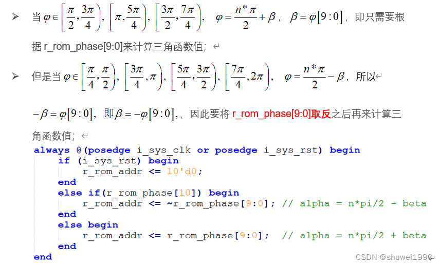
else if(r_rom_phase[10]) begin
r_rom_addr <= ~r_rom_phase[9:0]; // alpha = n*pi/2 - beta
end
else begin
r_rom_addr <= r_rom_phase[9:0]; // alpha = n*pi/2 + beta
end
end
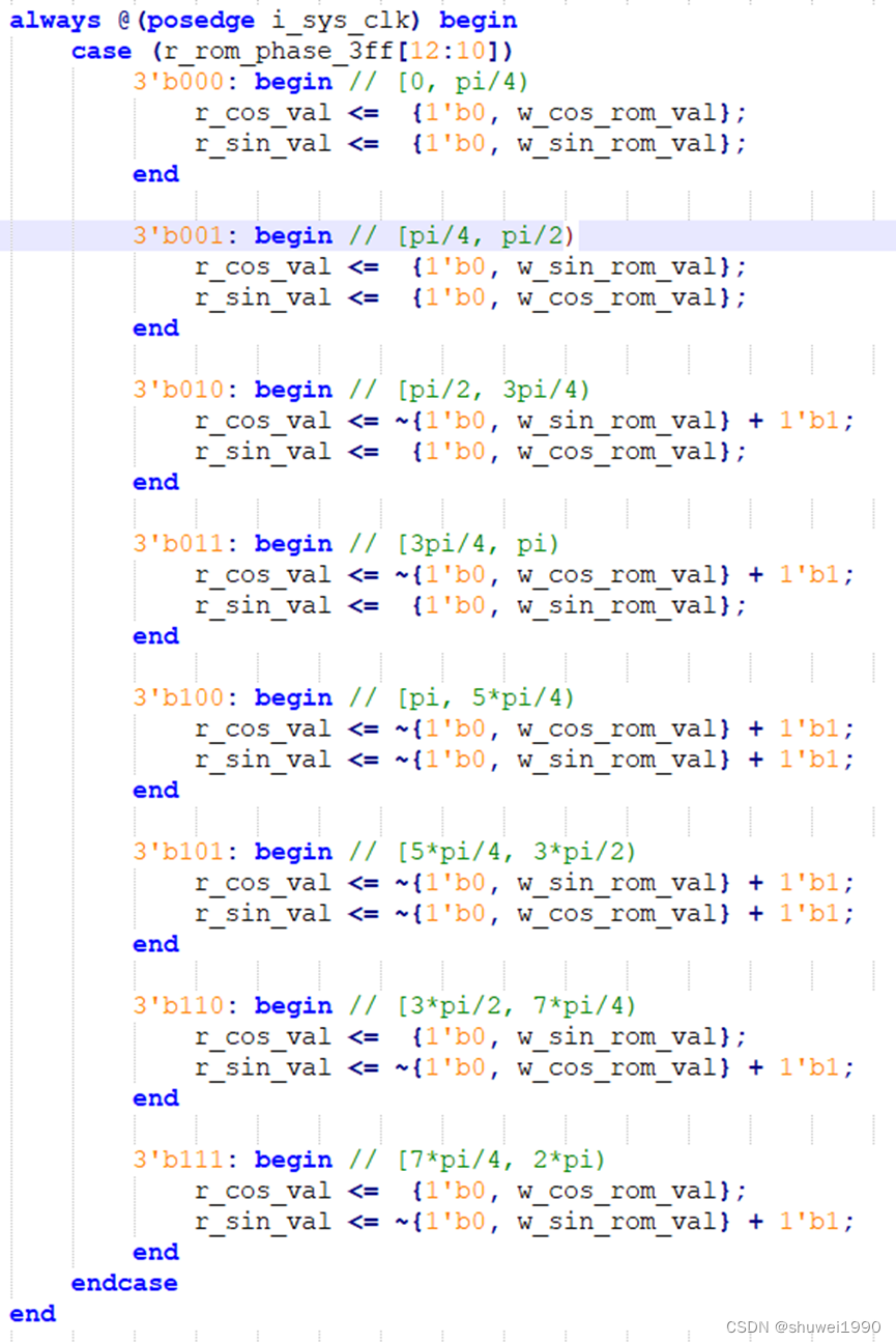
always @(posedge i_sys_clk) begin
case (r_rom_phase_3ff[12:10])
3'b000: begin // [0, pi/4)
r_cos_val <= {1'b0, w_cos_rom_val};
r_sin_val <= {1'b0, w_sin_rom_val};
end
3'b001: begin // [pi/4, pi/2)
r_cos_val <= {1'b0, w_sin_rom_val};
r_sin_val <= {1'b0, w_cos_rom_val};
end
3'b010: begin // [pi/2, 3pi/4)
r_cos_val <= ~{1'b0, w_sin_rom_val} + 1'b1;
r_sin_val <= {1'b0, w_cos_rom_val};
end
3'b011: begin // [3pi/4, pi)
r_cos_val <= ~{1'b0, w_cos_rom_val} + 1'b1;
r_sin_val <= {1'b0, w_sin_rom_val};
end
3'b100: begin // [pi, 5*pi/4)
r_cos_val <= ~{1'b0, w_cos_rom_val} + 1'b1;
r_sin_val <= ~{1'b0, w_sin_rom_val} + 1'b1;
end
3'b101: begin // [5*pi/4, 3*pi/2)
r_cos_val <= ~{1'b0, w_sin_rom_val} + 1'b1;
r_sin_val <= ~{1'b0, w_cos_rom_val} + 1'b1;
end
3'b110: begin // [3*pi/2, 7*pi/4)
r_cos_val <= {1'b0, w_sin_rom_val};
r_sin_val <= ~{1'b0, w_cos_rom_val} + 1'b1;
end
3'b111: begin // [7*pi/4, 2*pi)
r_cos_val <= {1'b0, w_cos_rom_val};
r_sin_val <= ~{1'b0, w_sin_rom_val} + 1'b1;
end
endcase
end
assign o_cos_val = r_cos_val[16:1];
assign o_sin_val = r_sin_val[16:1];
//-----------------------------------------------------------------------------------------------
cos_sin_lut_3 u_cos_sin_lut_3(
.clka ( i_sys_clk ), // input wire clka
.addra ( r_rom_addr ), // input wire [9 : 0] addra
.douta ({w_sin_rom_val, w_cos_rom_val}) // output wire [31 : 0] douta
);
endmodule
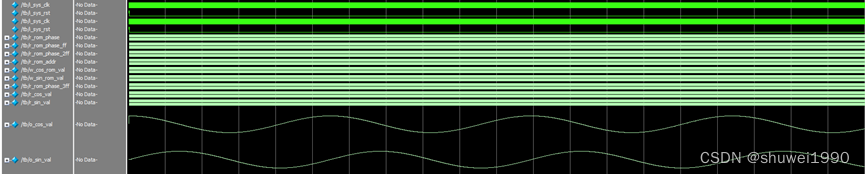
4、仿真结果
5、关键代码分析
- 使用10bit数据来量化pi/4,即pi/4 = 2^10,也即r_rom_phase = 13'b0_0100_0000_0000;
- 所以我们只需要根据r_rom_phase[12:10]来判断输入角度处于8段的哪一段;
- 然后根据三角函数公式调整最终输出值。


 1万+
1万+


 被折叠的 条评论
为什么被折叠?
被折叠的 条评论
为什么被折叠?
 到【灌水乐园】发言


