


 本文档详细介绍了如何在Altera Quartus 13.1环境下,针对DE2-115开发板创建一个包含NIOS处理器、以太网接口和Web服务器功能的系统。教程涵盖了从新建项目到配置各种组件,如SDRAM控制器、Flash接口、Triple-Speed Ethernet MAC以及Scatter-Gather DMA控制器的完整步骤,并提到了NIOS软件构建过程和相关注意事项。
这里综合了Altera提供的各种文献和实例,在最新的Quartus 13.1构建。
1. New Project
2.Create New System
Ctrl+R,将时钟Name更改为clk_50,频率为50MHz

加入altpll组件,c0->100MHz,作为系统时钟;c1->100MHz,相位延迟-2ns,作为SDRAM时钟;C2->10MHz,作为其他LCD,LED等时钟;可选C3->65MHz,作为VGA像素时钟。(图就不改了)

在View菜单中,打开Clocks视图,修改时钟名字提高易读性。分别是altpll_sys, altpll_sdram, altpll_io, altpll_vga。

altpll.inclk_interface设置为clk_50,双击altpll的export,导出areset,locked,phasedone。这个locked信号可以做nios的reset
加入NIOS Processor,JTAG UART(IRQ 0)
加入SDRAM controller,导出wire,地址锁定为0x0


各component的clk均为altpll_sys,sdram的Avalon Memory Mapped Slave连接到cpu.data_master和instruction_master。

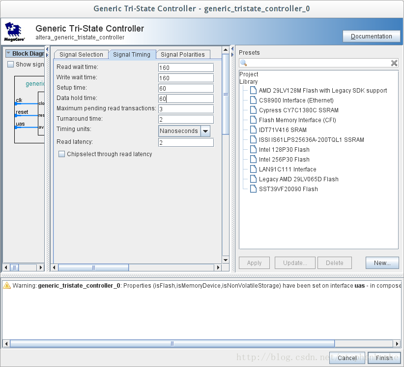
添加Generic Tri-State Controller,作为Common Flash Interface,名字为ext_flash(和web server app模版名字相同)

添加Tri-State Conduit Bridge作为Flash的端口,连接ext_flash.uas->cpu.data_master,ext_flash.tcm->tristate_conduit_bridge_flash.tcs,导出tristate_conduit_bridge_flash.out

add Triple-Speed Ethernet,名字为tse_mac(web sever模板中的名字),Core Variations: 10/10/100Mb Ethernet MAC,Interface RGMII,Include MDIO Module (MDC/MDIO)
terASIC提供的DE2_115_Web_Server.qsys中Triple-Speed Ethernet的名字有错(13改了名?)。可用文本编辑器修改此qsys文件,查找triple_speed_ethernet,修改module为:
<module kind="altera_eth_tse" version="13.1" enabled="1" name="tse_mac">

add scatter-gatter dma controller,Memory To Stream,Source error width为1,作为发送DMA

再次add scatter gather dma controller,Stream To Memory,Sink error width为6

tse, descriptor memory, dma时钟都是alt_sys。
tse.control_port->cpu.data_master
tse.receive_clock->altpll_sys
tse.transmit_clock->altpll_sys
接收链路:tse.receive->sgdma_rx.in, sgdma_rx.m_write->sdram.s1
发送链路:sgdma_tx.m_read->sdram.s1, sgdma_tx.out->tse.trnsmit
sgdma_rx, sgdma_tx两者的descriptor read 和descriptor write,都连接到descriptor_memory.s1,->cpu.data_master
sgdma_rx设置irq 2,sgdma_tx设置irq 3
根据提示导出tse的conduits

以上时钟都适用系统时钟,mapped slave都连接到cpu.data_master上,包括altpll.pll_slave
添加Avalon-MM Clock Crossing Bridge,设置适当深度

clock_crossing_bridge.m0_clk->altpll_io,clock_crossing_bridge.s0_clk->altpll_sys,clock_crossing_bridge.s0->cpu.data_master。
除非特别说明,以下系统的低速设备都使用altpll_io和clock_crossing_bridge.m0连接到clk和mapped slave (s1)。
add Interval Timer (IRQ 1), System ID, LCD 16027, LED pio (led_pio), SWITCH pio, Seven Segment Display pio, KEY pio (可将KEY[0]留作全局reset)
这里强调一点:System ID是很重要的一个设备,设定一个常数,和timestamp配合判断NIOS和你的BSP是否匹配,不要在Run Configuration 中采取 Ignore mismatched system timestamp,我常常因为这个 mismatch 的提示才知道bsp不匹配。
修改cpu,reset vector memory 和 exception vector memory 都设置为 sdram.s1
菜单System -> Create Global Reset Network
System -> assign base address
FIle -> Save
应当只有一个警告
Warning: System.flash: Properties (isFlash,isMemoryDevice,isNonVolatileStorage) have been set on interface uas - in composed mode these are ignored
终于可以:Generate -> Generating...
Generate -> HDL example, copy
3. Create a new DDIO_OUT megafunction variation
width 设置为 1bit,Neither asynchronous clear nor asynchronous set ports options.
4. Create a new altpll megafunction variation
输入时钟为以太网的接收时钟,c0:125MHz; c1: 125MHz, 90deg; c2:125MHz, 180deg

5. New systemverilog file
paste HDL example
从terasic提供的例子中copy端口描述部分
修改nios的实例化部分
`define NET0
module web_server(


<span style="white-space:pre">	</span> CLOCK //
<span style="white-space:pre">	</span>CLOCK_50,
  CLOCK2_50,
  CLOCK3_50,
<span style="white-space:pre">	</span>ENETCLK_25,


<span style="white-space:pre">	</span> Sma //
<span style="white-space:pre">	</span>SMA_CLKIN,
<span style="white-space:pre">	</span>SMA_CLKOUT,


<span style="white-space:pre">	</span> LED //
<span style="white-space:pre">	</span>LEDG,
<span style="white-space:pre">	</span>LEDR,


<span style="white-space:pre">	</span> KEY //
<span style="white-space:pre">	</span>KEY,


<span style="white-space:pre">	</span> SW //
<span style="white-space:pre">	</span>SW,


<span style="white-space:pre">	</span> SEG7 //
<span style="white-space:pre">	</span>HEX0,
<span style="white-space:pre">	</span>HEX1,
<span style="white-space:pre">	</span>HEX2,
<span style="white-space:pre">	</span>HEX3,
<span style="white-space:pre">	</span>HEX4,
<span style="white-space:pre">	</span>HEX5,
<span style="white-space:pre">	</span>HEX6,
<span style="white-space:pre">	</span>HEX7,


<span style="white-space:pre">	</span> LCD //
<span style="white-space:pre">	</span>LCD_BLON,
<span style="white-space:pre">	</span>LCD_DATA,
<span style="white-space:pre">	</span>LCD_EN,
<span style="white-space:pre">	</span>LCD_ON,
<span style="white-space:pre">	</span>LCD_RS,
<span style="white-space:pre">	</span>LCD_RW,


<span style="white-space:pre">	</span> RS232 //
<span style="white-space:pre">	</span>UART_CTS,
<span style="white-space:pre">	</span>UART_RTS,
<span style="white-space:pre">	</span>UART_RXD,
<span style="white-space:pre">	</span>UART_TXD,


<span style="white-space:pre">	</span> PS2 //
<span style="white-space:pre">	</span>PS2_CLK,
<span style="white-space:pre">	</span>PS2_DAT,
<span style="white-space:pre">	</span>PS2_CLK2,
<span style="white-space:pre">	</span>PS2_DAT2,


<span style="white-space:pre">	</span> SDCARD //
<span style="white-space:pre">	</span>SD_CLK,
<span style="white-space:pre">	</span>SD_CMD,
<span style="white-space:pre">	</span>SD_DAT,
<span style="white-space:pre">	</span>SD_WP_N,


<span style="white-space:pre">	</span> VGA //
<span style="white-space:pre">	</span>VGA_B,
<span style="white-space:pre">	</span>VGA_BLANK_N,
<span style="white-space:pre">	</span>VGA_CLK,
<span style="white-space:pre">	</span>VGA_G,
<span style="white-space:pre">	</span>VGA_HS,
<span style="white-space:pre">	</span>VGA_R,
<span style="white-space:pre">	</span>VGA_SYNC_N,
<span style="white-space:pre">	</span>VGA_VS,


<span style="white-space:pre">	</span> Audio //
<span style="white-space:pre">	</span>AUD_ADCDAT,
<span style="white-space:pre">	</span>AUD_ADCLRCK,
<span style="white-space:pre">	</span>AUD_BCLK,
<span style="white-space:pre">	</span>AUD_DACDAT,
<span style="white-space:pre">	</span>AUD_DACLRCK,
<span style="white-space:pre">	</span>AUD_XCK,


<span style="white-space:pre">	</span> I2C for EEPROM //
<span style="white-space:pre">	</span>EEP_I2C_SCLK,
<span style="white-space:pre">	</span>EEP_I2C_SDAT,


<span style="white-space:pre">	</span> I2C for Audio and Tv-Decode //
<span style="white-space:pre">	</span>I2C_SCLK,
<span style="white-space:pre">	</span>I2C_SDAT,


<span style="white-space:pre">	</span> Ethernet 0 //
<span style="white-space:pre">	</span>ENET0_GTX_CLK,
<span style="white-space:pre">	</span>ENET0_INT_N,
<span style="white-space:pre">	</span>ENET0_MDC,
<span style="white-space:pre">	</span>ENET0_MDIO,
<span style="white-space:pre">	</span>ENET0_RST_N,
<span style="white-space:pre">	</span>ENET0_RX_CLK,
<span style="white-space:pre">	</span>ENET0_RX_COL,
<span style="white-space:pre">	</span>ENET0_RX_CRS,
<span style="white-space:pre">	</span>ENET0_RX_DATA,
<span style="white-space:pre">	</span>ENET0_RX_DV,
<span style="white-space:pre">	</span>ENET0_RX_ER,
<span style="white-space:pre">	</span>ENET0_TX_CLK,
<span style="white-space:pre">	</span>ENET0_TX_DATA,
<span style="white-space:pre">	</span>ENET0_TX_EN,
<span style="white-space:pre">	</span>ENET0_TX_ER,
<span style="white-space:pre">	</span>ENET0_LINK100,


<span style="white-space:pre">	</span> Ethernet 1 //
<span style="white-space:pre">	</span>ENET1_GTX_CLK,
<span style="white-space:pre">	</span>ENET1_INT_N,
<span style="white-space:pre">	</span>ENET1_MDC,
<span style="white-space:pre">	</span>ENET1_MDIO,
<span style="white-space:pre">	</span>ENET1_RST_N,
<span style="white-space:pre">	</span>ENET1_RX_CLK,
<span style="white-space:pre">	</span>ENET1_RX_COL,
<span style="white-space:pre">	</span>ENET1_RX_CRS,
<span style="white-space:pre">	</span>ENET1_RX_DATA,
<span style="white-space:pre">	</span>ENET1_RX_DV,
<span style="white-space:pre">	</span>ENET1_RX_ER,
<span style="white-space:pre">	</span>ENET1_TX_CLK,
<span style="white-space:pre">	</span>ENET1_TX_DATA,
<span style="white-space:pre">	</span>ENET1_TX_EN,
<span style="white-space:pre">	</span>ENET1_TX_ER,
<span style="white-space:pre">	</span>ENET1_LINK100,


<span style="white-space:pre">	</span> TV Decoder //
<span style="white-space:pre">	</span>TD_CLK27,
<span style="white-space:pre">	</span>TD_DATA,
<span style="white-space:pre">	</span>TD_HS,
<span style="white-space:pre">	</span>TD_RESET_N,
<span style="white-space:pre">	</span>TD_VS,


<span style="white-space:pre">	</span>/// USB OTG controller
<span style="white-space:pre">	</span>OTG_DATA,
<span style="white-space:pre">	</span>OTG_ADDR,
<span style="white-space:pre">	</span>OTG_CS_N,
<span style="white-space:pre">
最低0.47元/天 解锁文章


 3989
3989

 被折叠的 条评论
为什么被折叠?
被折叠的 条评论
为什么被折叠?
 到【灌水乐园】发言


