


 本文介绍了如何在ESP32上通过按键实现长按配网,并通过LED灯显示网络状态。通过添加新文件和修改CMakeList,实现了按键清除配网信息和LED灯的不同状态指示网络连接情况。使用了esp-iot-solution库的button模块检测按键长按,并使用系统定时器控制LED灯的闪烁。当长按按键3秒后,设备会清除配网信息并重启进入等待配网状态,联网过程中LED快闪,连接成功后常亮。
前言
上面我们已经可以通过 ESPTOUCH 和 Airkiss 给模块配网,并且存储在 nvs 中,重启后仍然可以联网,只是这样仍然不能满足我们实际的应用,这次我们增加按键作为输入,LED作为输出,实现长按按键配网,并可以通过LED指示网络状态。
添加自己的组件
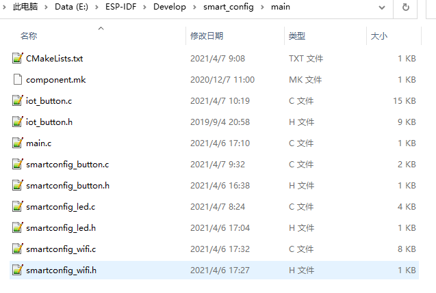
为了让程序结构更加清晰,所以我们在smart_config例程的基础上做了修改,在main文件夹里新建了main.c 、smartconfig_button.c , smartconfig_led.c ,将原来的smartconfig_main.c改为smartconfig_wifi.c,及其对应的.h文件
增加文件后,然后将 CMakeList.txt 文件修改为:
idf_component_register(SRCS “iot_button.c” “smartconfig_wifi.c” “smartconfig_button.c” “smartconfig_led.c” “main.c”
INCLUDE_DIRS “.”)
增加按键清除配网信息的功能
这里我们使用了乐鑫官方有个仓库叫做esp-iot-solution,里面有很多常用外设的驱动和物联网场景的实现代码。其中就有一个button模块来实现按键的长按、短按检测,我们将 botton 模块里的 iot_button.c 和 iot_button.h 文件添加到main文件夹中。
然后实现通过 smartconfig_button.c 文件实现长按清除网络信息的功能,具体如下:
//--------------- smartconfig_button.c ---------------//
#include <stdio.h>
#include <string.h>
#include <stdlib.h>
#include "freertos/FreeRTOS.h"
#include "esp_log.h"
#include "nvs_flash.h"
#include "driver/gpio.h"
#include "iot_button.h"
#include "smartconfig_button.h"
#include "smartconfig_wifi.h"

#define BUTTON_IO_NUM           0   //GPIO0
#define BUTTON_ACTIVE_LEVEL     0   //信号有效电平:低电平

static const char* TAG_BTN = "SMARTCONFIG_BUTTON";

void button_tap_cb(void* arg)
{
    char* pstr = (char*) arg;
    pstr = pstr;
    ESP_LOGI(TAG_BTN, "key tap \n");
}

void button_press_3s_cb(void* arg)
{
    char* pstr = (char*) arg;
    pstr = pstr;
    ESP_LOGI(TAG_BTN,"key 3s long press\n");                    //按键长按,清除配网信息并重启
    nvs_handle_t wificonfig_set_handle;
    ESP_ERROR_CHECK( nvs_open("wificonfig",NVS_READWRITE,&wificonfig_set_handle) );
    ESP_ERROR_CHECK( nvs_set_u8(wificonfig_set_handle,"WifiConfigFlag", wifi_unconfiged) );
    ESP_ERROR_CHECK( nvs_commit(wificonfig_set_handle) );
    nvs_close(wificonfig_set_handle);

    ESP_LOGI(TAG_BTN,"Set Restart now.\n");
    esp_restart();
}

void smartconfig_button_init(void)
{
    //配置配网按键
    button_handle_t btn_handle = iot_button_create(BUTTON_IO_NUM, BUTTON_ACTIVE_LEVEL);
    //注册单击事件
    iot_button_set_evt_cb(btn_handle, BUTTON_CB_TAP, button_tap_cb, "TAP");
    //注册 3s 长按事件
    iot_button_add_custom_cb(btn_handle, 3, button_press_3s_cb, NULL);

}
加入配网指示灯
灯的不同状态代表不同的配网状态,设定:慢闪代表未联网,快闪代表正在联网,长亮代表网络已连接。这里会用到ESP32的系统定时器,使用方法也比较简单,创建定时器,开启或者关闭定时器,源码如下:
//--------------- smartconfig_led.c ---------------//
#include <stdio.h>
#include <string.h>
#include <stdlib.h>
#include "driver/gpio.h"
#include "esp_timer.h"
#include "esp_log.h"
#include "smartconfig_led.h"

#define WIFI_STATUS_LED_GPIO  15

static const char* TAG = "WIFI_STATUS_LED";
static esp_timer_handle_t  smartconfig_led_soft_timer;

//定时器回调里实现灯的闪烁
static void periodled_timer_callback(void* arg)
{
    static uint8_t s_LEDToggle  = 0;
    s_LEDToggle = ~s_LEDToggle;

    if(s_LEDToggle)
    {
        gpio_set_level(WIFI_STATUS_LED_GPIO, 1);
    }
    else
    {
        gpio_set_level(WIFI_STATUS_LED_GPIO, 0);
    }
}

static void handle_smartconfig_led_status(Wifi_Status_t WifiState)
{
    static uint8_t s_WifiDisconnectNotice;
    switch(WifiState)
    {
        case WIFI_DISCONNECT:

            if(s_WifiDisconnectNotice == 0)
            {
                ESP_ERROR_CHECK(esp_timer_start_periodic(smartconfig_led_soft_timer, ConnectStatusInterval));
                s_WifiDisconnectNotice = 1;
            }
            break;
        case WIFI_CONNECTING:
            //正在联网的时候LED快闪
            if(s_WifiDisconnectNotice == 1)
            {
                ESP_ERROR_CHECK(esp_timer_stop(smartconfig_led_soft_timer));
            }
            ESP_ERROR_CHECK(esp_timer_start_periodic(smartconfig_led_soft_timer, DisconnectStatusInterval));
            break;
        case WIFI_CONNECTED:
            //连上网后LED常亮,并注销软件定时器,减少消耗
            gpio_set_level(WIFI_STATUS_LED_GPIO, 1);
            if(s_WifiDisconnectNotice == 1)
            {
                ESP_ERROR_CHECK(esp_timer_stop(smartconfig_led_soft_timer));
                ESP_ERROR_CHECK(esp_timer_delete(smartconfig_led_soft_timer));
                s_WifiDisconnectNotice = 0;
            }
            break;
        default:
            break;
    }
}

//LED管脚初始化
void wifi_status_led_init(void)
{
    gpio_config_t smartconfig_IO_conf;
    smartconfig_IO_conf.intr_type = GPIO_PIN_INTR_DISABLE;
    smartconfig_IO_conf.mode = GPIO_MODE_OUTPUT;
    smartconfig_IO_conf.pin_bit_mask = 1 << WIFI_STATUS_LED_GPIO;
    smartconfig_IO_conf.pull_down_en = 0;
    smartconfig_IO_conf.pull_up_en = 0;
    gpio_config(&smartconfig_IO_conf);
    gpio_set_level(WIFI_STATUS_LED_GPIO, 0);

     esp_timer_create_args_t periodled_timer_args = {
            .callback = &periodled_timer_callback,
            /* name is optional, but may help identify the timer when debugging */
            .name = "periodled"
    };
    ESP_ERROR_CHECK(esp_timer_create(&periodled_timer_args, &smartconfig_led_soft_timer));
}

//通知网络未连接
void delegate_wifi_disconnect_status(void)
{
    ESP_LOGI(TAG,"Delegate wifi is disconnect\n");
    handle_smartconfig_led_status(WIFI_DISCONNECT);

}
//通知网络已连接
void delegate_wifi_connected_status(void)
{
    ESP_LOGI(TAG,"Delegate wifi has connected\n");
    handle_smartconfig_led_status(WIFI_CONNECTED);

}
//通知网络正在连接中
void delegate_wifi_connecting_status(void)
{
    ESP_LOGI(TAG,"Delegate wifi is connecting\n");
    handle_smartconfig_led_status(WIFI_CONNECTING);
}

//--------------- smartconfig_led.h ---------------//
#ifndef __SMARTCONFIG_LED_H__
#define __SMARTCONFIG_LED_H__

#ifdef __cplusplus
extern "C" {
#endif

#define ConnectStatusInterval    1000000    //单位为us
#define DisconnectStatusInterval 200000

typedef enum{
    WIFI_DISCONNECT = 1,
    WIFI_CONNECTING,
    WIFI_CONNECTED,
}Wifi_Status_t;


void wifi_status_led_init(void);
void delegate_wifi_disconnect_status(void);
void delegate_wifi_connected_status(void);
void delegate_wifi_connecting_status(void);

#ifdef __cplusplus
}
#endif


#endif
主函数
删除 smartconfig_wifi.c 中的 app_main() 函数,在 main.c 中增加如下源码:
#include <string.h>
#include <stdlib.h>
#include "freertos/FreeRTOS.h"
#include "freertos/task.h"
#include "freertos/event_groups.h"
#include "esp_log.h"
#include "nvs_flash.h"
#include "smartconfig_button.h"
#include "smartconfig_wifi.h"
#include "smartconfig_led.h"


void app_main(void)
{
    ESP_ERROR_CHECK( nvs_flash_init() );
    wifi_status_led_init();
    smartconfig_button_init();

    //initialise_wifi();
    check_wifi_config_in_nvs();
}
实验结果
编译下载程序后,长按 Boot 按键 3S后,就自动清除配网标志位,并自动重启后,重启后就等待配网,同时LED闪烁,等网络连接后,LED指示灯常亮。
纯手写文章,转载请注明出处,谢谢!
如有任何错误,欢迎留言指正!


 440
440

 被折叠的 条评论
为什么被折叠?
被折叠的 条评论
为什么被折叠?
 到【灌水乐园】发言


