


作者
A. Nasri1∗, M. Sabin2 and Z. Yasseen1
1American University of Beirut, Department of Computer Science
2Numerical Geometry Ltd
2020/03/03 Jackdos整理翻译
Abstract摘要
Given an n-sided region bounded by a loop of n polylines, we present a general algorithm to fill such a region by a quad mesh suitable for a subdivision scheme.
该论文提出了一种适用于细分方法的四边形网格填充该区域的通用算法。
Typically, the approach consists of two phases: the topological phase and the geometrical phase. 通常,该方法包括两个阶段:拓扑阶段和几何阶段。
In the first part, the connectivity of the mesh is based on determining a partitioning of the region into rectangular subregions across which regular grid could be constructed. 在第一部分中,网格的连通性是基于确定将区域划分为矩形子区域的划分,在该子区域上可以构建规则网格。
The geometrical phase generalizes discrete Coon’s patches to position the vertices in the 3D space. 几何阶段将离散孔斯补片推广到三维空间中定位顶点。
The generated mesh could be taken as input to any quad-based subdivision scheme,
生成的网格可以作为任何基于四边形的细分方案的输入,
such as that of Catmull–Clark or Doo–Sabin to generate the corresponding limit surface.
如Catmull–Clark或Doo–Sabin,都可以生成相应的极限曲面。
The goal of the algorithm is to generate smooth meshes with minimum number and less valence of extraordinary vertices deemed undesirable in such subdivision schemes.
该算法的目标是生成数目最少且在这种细分方案中不受欢迎的非规则顶点数目较少的光滑网格。
Keywords
:subdivision surfaces, curve interpolation, quad mesh generation, hole filling, n-sided patches 关键词:细分曲面,曲线插值,四元网格生成,补孔,n边补片
ACM CCS: I.3.5 [Computer Graphics]: Computational Geometry and Object Modeling, curve, surface, solid, and object representations.
计算机图形学:计算几何和对象建模、曲线、曲面、实体和对象表示。
1. Introduction介绍
Filling n-sided holes is a central issue in surface modelling and computer graphics.
填充n边孔是曲面建模和计算机图形学的核心问题。
This problem is tightly coupled with the generation of n-sided patches to fill a hole that may occur in various situations,
这个问题与生成n边补片紧密结合在一起,以填补可能在各种情况下出现的漏洞,
such as when many traditional rectangular patches are assembled together.
例如将许多传统的矩形补片组装在一起。
Typically, the hole is defined by a loop of n curves, each defined by a control polygon (polyline),通常,孔由n条曲线组成的循环定义,每条曲线由一个控制多边形(折线)定义,
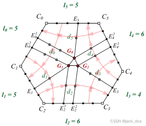
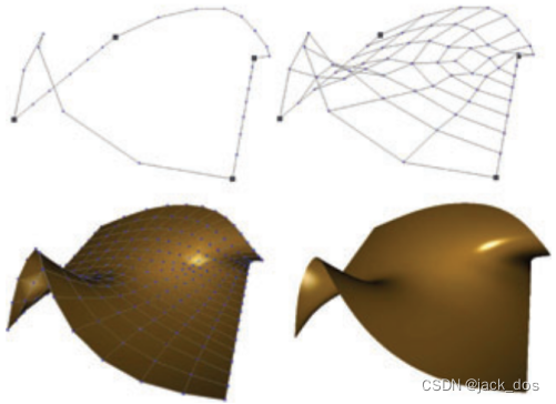
forming the boundary of the hole as depicted in Figure 1. 形成如图1所示的孔的边界。
The generalization of rectangular Coon’s patches to n-sided patches is then of a great interest.将矩形孔斯曲面片推广到n边补片,引起了人们极大的兴趣。
Since 1964, many methods emerged to address this problem, as outlined in the following Section. 自1964年以来,出现了许多方法来解决这个问题,如下一节所述。
In the discrete setting, filling rectangular regions with matching number of vertices on opposite boundary sides could be achieved using discrete Coon’s patches [FH99]. 在离散设置下,使用离散的孔斯曲面片可以实现在相对的边界边上用匹配数量的顶点填充矩形区域[FH99]。
If two opposite sides are defined by control polygons with different number of vertices, the solution is not trivial. 如果两个相对的边由顶点数目不同的控制多边形定义,解决方案并不简单。
In the case of B-spline, knot insertion could be used to match the number of vertices on both sides. 在b样条的情况下,可以使用节点插入来匹配两边的顶点数。
This, however, may not be possible if the control mesh of the hole is to be integrated in the polyhedron defining an existing subdivision surface.
然而,如果将孔的控制网格集成到定义现有细分曲面的多面体中,这可能是不可能的。
Besides, it results in adding unnecessary vertices to define the same shape.
此外,它会导致添加不必要的顶点来定义相同的形状。
Consequently, a more general solution to handle the filling of n-sided (n ≥ 3) region bounded by polylines with different number of vertices is still needed.
因此,还需要一种更通用的方法来处理n边(n≥3)区域被具有不同顶点数的折线所包围的填充问题。
In this paper we propose a coherent approach to address this issue.
在本论文中,我们提出了一个连贯的方法来解决这个问题。
The problem can thus be formulated as follows: given a region bounded by a loop of n polylines, 这个问题可以这样表述: 给定一个被n条折线包围的区域,
we need to determine a partitioning into rectangular subregions in which regular grid can be constructed. 我们需要确定一个划分为矩形子区域的区域,在这个区域中可以构造规则的网格。
As the subregions are being established, the need for a vertex incident to a number m (m ≠ 4) of edges could well be inevitable. We call such a vertex a dislocation.
随着子区域的建立,不可避免地需要与许多m (m≠4)条边关联的顶点。我们称这样的顶点为位错。
In the context of quad meshing, a dislocation vertex can be described as either negative when m < 4, or positive when m > 4.
在四元网格的情况下,位错顶点可以描述为m < 4时为负,也可以描述为m > 4时为正。
For quad-based subdivision schemes, such a vertex is called an extraordinary vertex.
对于基于四分法的细分方案,这种顶点被称为非平凡顶点。
In certain cases that will be investigated later, the dislocation could be a non-quadrilateral polygonal element that we call a facet dislocation.
在某些情况下,这种位错可能是一种非四边形的多边形元素,我们称之为小面位错。
Our proposed algorithm generates the quad mesh for a hole aiming at minimizing the number of dislocations.我们所提出的演算法以减少位错的数目为目标来产生一个孔的四元网格。
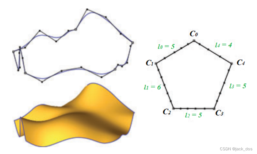 Figure 1: An example of filling a five-sided region. Top-left: the control polygons of five curves; right: The topological configuration of the region; bottom-left: the Catmull–Clark subdivision surface of the mesh generated by our algorithm.
图1:填充五边形区域的示例。左上角:五条曲线的控制多边形;右:区域的拓扑结构;左下:由我们的算法生成的网格的Catmull-Clark细分曲面。
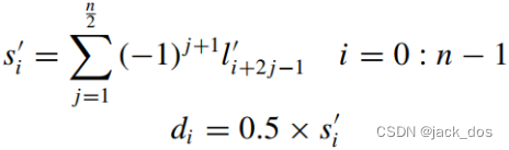
For quad-based subdivision scheme, the distortion d of a vertex v i of the mesh is defined by
在基于四分法的细分方案中,网格顶点v i的变形d定义如下
![]()
It is proven [SWZ04] that |n − 4| is a lower bound on the total distortion in a quadrangulated n-sided region, thus: 事实证明,|n−4|是四边形n边区域总畸变的一个下界,即:
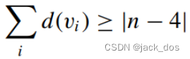
Our proposed algorithm creates a maximum of one n-valent dislocation in most cases, thus the total distortion is n − 4.
我们提出的算法在大多数情况下产生一个最大的n价位错,因此总失真为n−4。
We also generate quad meshes with as smooth flow as possible.
我们还生成尽可能圆滑的四变形网格。
This is indicated by the way and the number of flow lines directed from one side to the other.这是通过从一边到另一边的流线的方式和数量来表示的。
A flow line is simply a sequence of edges connecting a number of vertices by departing from one side and landing on another.
流线就是一系列边的序列,这些边通过从一边离开并落在另一边来连接大量的顶点。
The number of vertices on each flow line is determined by the solution of a system of linear equations.每条流线上的顶点数由一个线性方程组的解决定。
Throughout this paper, we will refer to distances or lengths as logical distances or logical lengths to describe the topology of the structure at hand.
在本论文中,我们将把距离或长度称为逻辑距离或逻辑长度,以描述当前结构的拓扑结构。
The logical distance between two vertices is the number of edges connecting them.
两个顶点之间的逻辑距离是连接它们的边的数目。
The logical length of a side is thus the number of edges connecting its two endpoints.
因此,边的逻辑长度就是连接两个端点的边的数量。
Let us assume that the side i of the hole has a length l i (l i ≥ 2).
假设某孔的第i边的长度为l i (l i ≥ 2 )。
Its endpoints C i and C i+1, where i is taken mod n, define the two corresponding corners at which other polylines connect to form the boundaries of the hole (see Figure 1).
它的端点C i和C i+1 (其中i对n取余)定义了其他折线连接起来形成孔边界的两个相应的角(参见图1)。
Typically, there are two phases in the filling algorithm: The topological phase and the geometrical phase. 通常,填充算法有两个阶段:拓扑阶段和几何阶段。
In the first phase, we determine how the internal vertices of the region shall be connected and in the second, how these vertices are positioned in space.
在第一阶段,我们确定区域内的顶点如何连接,在第二阶段,我们确定这些顶点在空间中的位置。
The proposed algorithm is focused on solving the topological problem and generalizes discrete Coon’s patches [FH99] to handle the geometrical phase.
该算法以求解拓扑问题为重点,将离散孔斯曲面片[FH99]推广到处理几何阶段。
The remainder of this paper is organized as follows. Section 2 gives an overview of related work. The general framework of the proposed filling algorithm is detailed out in Section 3. Filling quadrilateral regions need special attention and could be handled by extending the general algorithm as described in Section 4. In Section 5, we cover the geometrical phase that completes the process of mesh construction. Finally, discussions and limitations are give in Section 6, whereas conclusions and future work are outlined in Section 7.
本文的其余部分组织如下。第2节概述了相关工作。第3节详细介绍了所提出的填充算法的总体框架。第4节中,填充四边形区域需要特别注意,可以通过扩展通用算法来处理。在第5节中,我们将介绍完成网格构建过程的几何阶段。最后,讨论和限制在第6节,而结论和未来的工作概述在第7节。
2. Related Work相关工作
Filling n-sided holes bounded by a set of n curves or polylines is a central problem addressed in various domains. Computer Aided Geometric Design, finite element analysis, and texturing are some of these domains. In this section, we present an overview of some of the most related work to our proposed algorithm. For more details, the reader is referred to the references cited therein.
填充由n条曲线或折线组成的n边孔是各个领域的中心问题。计算机辅助几何设计、有限元分析和纹理是其中的一些领域。在本节中,我们将概述与我们所提议的算法最相关的一些工作。要了解更多的细节,读者可以参考其中引用的参考文献。
Malraison [Mal00] presented a brief survey of various techniques for filling n-sided regions. Generally there are three approaches for filling an n-sided region: the single patch approach, the splitting approach and the subdivision approach.
Malraison [Mal00]简要介绍了填充n边区域的各种技术。通常有三种方法来填充一个n边区域:单个patch方法、分割方法和细分方法。
In the first approach, a single multi-sided patch is defined, such as the Gregory patches [Gre86, HM97], the Sabin 3- and 5-sided patches [Sab83] which were extended to n-sided as in [ZB97, HK84], and the S-patches as in [LD90]. General overviews of these patches are also provided, such as those in Varady [Var87], Gregory et al. [GLZ90], and Hosaka [HK84].
在第一种方法中,我们定义了一个单一的多边patch,例如Gregory patches [Gre86, HM97], Sabin 3- and 5-sided patches [Sab83],将其扩展到n-sided,如[ZB97, HK84], S-patches如[LD90]。还提供了这些补丁的一般概况,如Varady [Var87]、Gregory等[GLZ90]和Hosaka [HK84]。
The second approach consists of filling a region with multiple patches. Typically, an initial vertex is chosen at the centre of the region, which is split into rectangular patches, such as the bicubic Hermite patches [BS89], or even the B-spline patches [PGVACN06], etc. The smoothness of the patches along the shared edges and in particular at the centre vertex required special attention. Our proposed algorithm does not require the input of a centre vertex.
第二种方法是用多个补丁填充一个区域。通常情况下,一个初始顶点被选择在区域的中心,该区域被分割成矩形块,如双三次Hermite块[BS89],甚至b样条块[PGVACN06]等。沿着共享的边缘,特别是中心顶点的平滑度需要特别注意。我们提出的算法不需要输入中心顶点。
The third and the more relevant approach to our algorithm is the one that uses subdivision surfaces. For instance, an nsided patch can be designed from Hermite data [BS89]. In the situation of vertex-corner blending such as those dealt with in Varady [VR97], Charrot and Gregory [CG84], Hwang et al. [HC03], subdivision is also used to fill the arising n-sided regions. Some specific schemes can be tuned to fill an n-sided hole such as the combined scheme as in Levin [Lev99]. Clearly, in most of these situations, an essential and decisive step is how to create a control mesh to be used as input to the underlying subdivision scheme. To do this, an arbitrary interior vertex, selected by the user, is typically employed. However, it is not intuitive how best to choose such a vertex.
第三种,也是与我们的算法更相关的一种方法是使用细分曲面。例如,可以根据Hermite数据设计一个n边patch [BS89]。在顶点角混合的情况下,如Varady [VR97]、Charrot和Gregory [CG84]、Hwang等[HC03],也使用细分来填充上升的n边区域。一些特定的方案可以调整来填补一个n边的洞,例如Levin [Lev99]中的组合方案。显然,在大多数情况下,一个关键和决定性的步骤是如何创建一个控制网格来作为底层细分方案的输入。为此,通常使用用户选择的任意内部顶点。然而,如何选择这样一个顶点是不直观的。
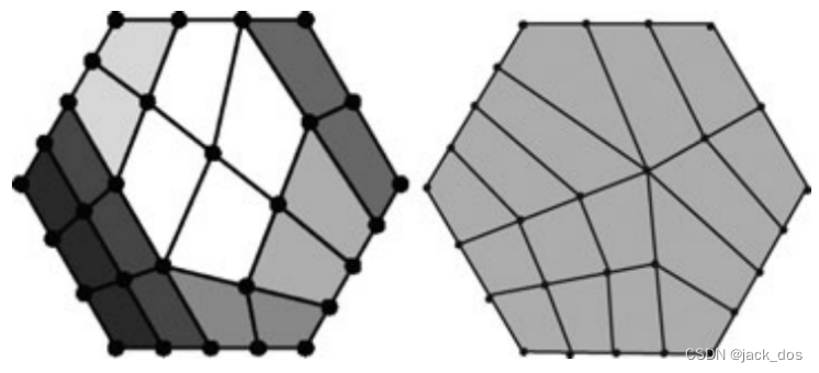 Figure 2: A comparison between the quadrangulation in Schaefer et al. [SWZ04] (left) and our scheme (right). 图2:Schaefer等人[SWZ04]的四边形(左)与我们的方案(右)的比较。
Schaefer et al. [SWZ04] partially addressed the filling of a region by quadrilateral elements in the context of constructing meshes over net of curves. While their work does not consider generating extraordinary vertices away from the boundary of the region as a priority to build on, we base the quadrangulation on extraordinary vertices being placed interior to the region, as depicted in Figure 2. To avoid this in Schaefer et al., this may require that the discrete lengths be sufficient enough. Being a recursive process, it is not easy to predict the topology of the generated mesh. Yet, they state that the maximum of (n − 2) 5-valent and two 3-valent extraordinary vertices are generated, thus obtaining a mesh with a total distortion of n. In general, our proposed algorithm generates a quadrangulation of minimal distortion of (n − 4). As such, our algorithm produces less extraordinary vertices with valency depending on the number of sides in a hole. In addition, they observe that their quad meshing algorithm produces a non-quadrilateral face if the summation of all the lengths of the boundary polylines is odd. When we discuss the need for non-quadrilateral faces, we show that this is partially but not always true.
Schaefer等人[SWZ04]在构建曲线网格的背景下,部分解决了四边形元素填充区域的问题。虽然他们的工作并没有将生成远离区域边界的非规则顶点作为优先级进行构建,但是我们将四边形基于放置在区域内部的非规则顶点,如图2所示。为了避免在Schaefer等人,这可能要求离散长度足够。作为一个递归的过程,对生成的网格的拓扑结构进行预测是不容易的。然而,他们国家的最大(n−2) 5-valent和两个3-valent非凡的顶点生成,从而获得网总失真n。总的来说,我们的算法生成一个quadrangulation最小失真的(n−4)。这样,我们的算法会产生更少的顶点和化合价的数量取决于双方在一个洞。此外,他们还观察到,如果所有边界折线长度之和为奇数,则他们的四元网格划分算法会产生一个非四边形的面。当我们讨论对非四边形面的需求时,我们表明这是部分正确的,但并不总是正确的。
Quad meshing or re-meshing schemes are also relevant to our work. The reader is referred to the surveys presented in [Owe98] and [AUGA05] for an overview of existing schemes and their categorizations. Each survey proposes different criterion for classification and evaluation. Our overview of quad mesh generation schemes classifies according to the global/local aspect in which the problem input is handled.
四分网格或重网格方案也与我们的工作相关。读者可以参考[Owe98]和[AUGA05]中提出的调查,以了解现有方案及其分类的概述。每次调查都提出不同的分类和评价标准。我们对四网格生成方案的概述是根据处理问题输入的全局/局部方面进行分类的。
In general, global treatment performs unified analysis over the input represented as boundary lines or triangular meshes. This analysis is done by defining a scalar function, vector fields, parametrization, optimization, or other operations. Although these schemes mostly produce satisfactory results, their potential drawback is the high complexity of the algorithm and its low efficiency. Alliez et al. [ACSD∗03], Marinov and Kobbelt [MK04], Ray et al. [RLL∗06], and Dong et al. [DKG05] use vector fields for anisotropic mesh generation. Others such as Lee et al. [LMH00] Litke et al. [LLS01], and Dupont et al. [LDB07] fit scanned geometry to template subdivision surfaces. Some quad meshing algorithms are based on parametrization methods [BMRJ04, GGH02, HG00, EH96]. Quadros et al. [QRPG] use medial axis transform to quadrangulate the region enclosed by the input boundary lines. Shimada et al. [SL98] propose a computational method that creates quad meshes by a node placement and connection procedure.
通常,全局处理对以边界线或三角形网格表示的输入进行统一分析。这种分析是通过定义标量函数、向量场、参数化、优化或其他操作来完成的。虽然这些方案大多能得到令人满意的结果,但其潜在的缺点是算法复杂度高、效率低。Alliez等人[ACSD∗03],Marinov和Kobbelt [MK04], Ray等人[RLL∗06], Dong等人[DKG05]使用向量场进行各向异性网格生成。Lee等人[LMH00] Litke等人[LLS01]和Dupont等人[LDB07]将扫描几何图形贴合到模板细分表面。一些四元网格划分算法是基于参数化方法[BMRJ04, GGH02, HG00, EH96]。Quadros等人[QRPG]利用中轴变换对输入边界线包围的区域进行四边形划分。Shimada等人[SL98]提出了一种通过节点放置和连接过程来创建四网格的计算方法。
The techniques that create quad elements by applying local operations usually lack to guarantee for the topological regularity of the resulting mesh.
通过应用局部操作创建四元网格的技术通常缺乏对生成网格的拓扑规则性的保证。
The advancing front techniques [CBMB96, WK, PNJK07] start with a set of fronts consisting of the edges at the boundary of the domain. Quads are systematically combined at the front, advancing towards the interior of the area. 前沿技术[CBMB96, WK, PNJK07]从一组前沿开始,包括领域边界的边缘。方阵在前方有系统地组合,向区域内部推进。
If the input is a triangular mesh Owen et al. [OSCS99] and Merhof et al. [MGTG07] perform local operations to convert triangles to quadrilateral elements.如果输入是三角形网格,Owen等[OSCS99]和Merhof等[MGTG07]进行局部操作,将三角形转换为四边形元素。
As outlined in the following section, our proposed algorithm provides a coherent theory for this mesh construction problem, generating coarse grids that match the density requirements along the given boundary edges.如下一节所述,我们提出的算法为这个网格结构问题提供了一个一致的理论,生成的粗网格符合给定边界边的密度要求。(这里的density是指折线上的顶点数。)
3. The General Framework Filling Algorithm一般框架填充算法
The input to the problem is a closed configuration of n polylines (p i) meeting at their endpoints. Each polyline p i has a length denoted by l i and connects its two endpoints C i and C i+1. Note that the indices throughout this paper are always taken mod n.
该问题的输入是n条折线(p i)在其端点处相交的封闭配置。每个折线p i的长度用l i表示,并将两个端点连接起来,即C i和C i+1。注意,整篇论文的下标都是对n取余。
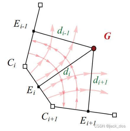
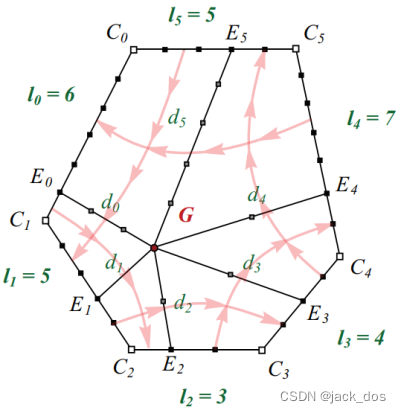
Figure 3: The general solution that partitions the region into n quadrilateral regions: G connects to all boundary polyline by d i long rays that meet the edges at E i. The light red lines show the direction of the flow lines between the sides of the region.
图3:将区域划分为n个四边形区域的通解:G通过在E i处与边相接的d i长射线与所有边界折线相连,其中的淡红箭头线表示区域两侧流线的方向。
In order to construct the quad mesh that fills the region defined by the closed loop of these n polylines,为了构建填充这n条折线的闭合环所定义的区域的四元网格,
a typical solution is to split this region into a partitioning of rectangular subregions across which regular grid can be constructed.
一个典型的解决方案是将这个区域分割成一个矩形子区域的划分,在这些子区域之间可以构建规则的网格。
As the partioning is determined, the direction of flow of the vertices from one boundary polyline to another lays out the topology of the interior of the generated mesh.
当剖分确定后,顶点从一个边界折线到另一个边界折线的流动方向确定了生成的网格内部的拓扑结构。
To present the main idea of the algorithm, let G be a dislocation located at a distance d i from each boundary polyline p i.
为了说明算法的主要思想,设G为一个位错,位于每个边界折线p i的距离d i处。
A ray of length d i initiates from G and hits the i side (defined by the polyline pi) at a vertex E i as depicted in Figure 3.
一条长度d i的射线从G出发,到达i边(由折线p i定义)的一个顶点E i。(图3),
Note that n is arbitrary and as such, the valence of G is n.
注意,n是任意的,因此,G的价为n。
Consider the n quadrilateral regions constructed by the corners G, E i -1, C i, and E i.
想一下,这n个四边形区域由角G、E i -1、C i和E i构成的。
In order to construct quad meshes within these regions without any other dislocation,
为了在这些区域内构造四边形网格而不产生任何其他错位,
the conditions are, for each i: 对于每一个i的条件是:
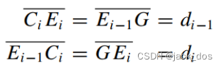
where ![]() is the distance between the vertices A and B.These conditions imply that:
is the distance between the vertices A and B.These conditions imply that:
AB是顶点A和B之间的距离。这些条件意味着:

Having this partitioning, we construct regular grids across each rectangular region.
有了这种划分,我们就可以在每个矩形区域上构建规则的网格。
The primary unknown of the analysis is the distance d i. 分析的主要未知数是距离di。
In what follows, we discuss the existence and feasibility of d i
在接下来的分析中,我们讨论了d i的存在性和可行性,
and construct the topological outcome of the solution in terms of rectangular regions, and vertex or facet dislocations.
并根据矩形区域和顶点或面位错构造了解的拓扑结果。
3.1. Existence of the solution方案的存在性
The rectangular partitioning of the region implies relations between interior unknown distances d i and the known lengths of the sides of the region l i. Consider the other form of relation 1
区域的矩形划分意味着内部未知距离d i和区域l i的已知边长之间的关系。考虑关系1的另一种形式
![]()
We denote by sub(1) the first substitution of relation 2 that is:
我们用sub(1)表示关系2的第一个代换
![]()
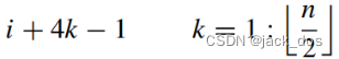
We can prove by induction that after the kth substitution, we obtain:
我们可以通过归纳法证明,在第k次替换后,我们得到:
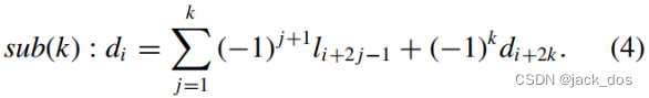
The relation binding the d i unknowns to each other orders the system in a circular way.
将d i未知数相互绑定的关系以一种循环的方式对系统进行排序。
Under certain conditions, this ordering results in the reappearance of d i in the right-hand side of Equation (4). These conditions must imply that for some k = k 0 we have
在一定条件下,这种排序会导致方程(4)的右边再次出现d i。这些条件一定意味着对于k = k 0,我们有
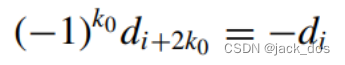
That is:那么
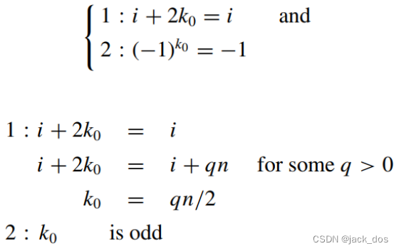
Because k 0 is the number of substitutions needed to make Equation (4) with one unknown, the smallest value of k 0 is enough.
因为k 0是令方程(4)含有一个未知数所需要的替换次数,所以k 0的最小值就足够了。
It can be easily shown that using higher values of k 0 in the above conditions will only result in additional computation yielding the same solution for d i.
可以很容易地看出,在上述情况下使用较高的k 0值只会导致对d i产生相同的解的额外计算。
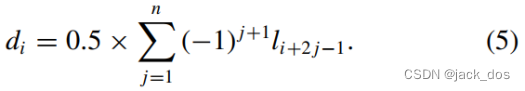
The following cases can then be considered:然后可以考虑以下情况:
Case n is odd The smallest value of k 0 could be obtained by q = 2 giving k 0 = n and
当n为奇数时,k 0的最小值可以由q = 2得到,其中k 0 = n,那么
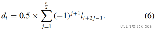
Case n is even Here q = 1 gives the smallest k 0 = n/2i A solution then exists iff k 0 = n/2 is odd, that is n is not a multiple of 4 and
当n为偶数时,这里q = 1给出了最小的k 0 = n/2i一个解, 然后存在当且仅当 k 0 = n/2是奇数,那就是n不是4的倍数,那么
3.2. Feasibility of the solution方案的可行性
The discussion presented in the previous section yields the two formulae in 5 and 6 to calculate d i.
上一节的讨论给出了计算d i的两个公式(5)(6)。
In the case where n is even, the formula is valid if n/2 is odd.
当n为偶, n/2为奇时,这个公式是有效的。
An even value of n/2 eliminates d i from the equation by making its coefficients on both sides equal to +1.当n/2的偶值时,使方程两边的系数都为+1,从而消除了d i。
Therefore, this algorithm provides a solution when n mod 4 ≠ 0
因此,当n不能被4整除时,该算法提供了一种求解方法
Clearly, d i must be a positive integer. 显然,d i一定是正整数。
The following sections investigate the conditions and treatments under which this requirement is realized. 下面几节将研究实现这一要求的条件和处理方法。
3.3. Conditions for integer solutions整数解的条件
Clearly Equations (5) and (6) guarantee the existence of a solution but the 0.5 factor could possibly make it non-feasible. 显然,式(5)和式(6)保证了解的存在,但0.5因子可能使其不可行。
For instance, an integer solution for d i requires this value of the summation to be even.
例如,d i的整数解决方案要求总和的这个值是偶数。
In what follows we show that there are three patterns of the rectangular partitioning depending on the configuration of a region as follows.
在接下来的内容中,我们展示了根据一个区域的配置,有三种矩形分区的模式,如下所示。
• Case n is odd 当n是奇数时

therefore d i is integer iff s i is even, that is iff ![]() is even.
is even.
因此,当且仅当s i是偶数时,d i是整数,当且仅当![]() 是偶数时。
是偶数时。
If![]() is even, we obtain a set of n rectangular regions and a positive n-valent vertex dislocation exactly as described in the general solution (see Figures 4 and 5(a)). 如果
is even, we obtain a set of n rectangular regions and a positive n-valent vertex dislocation exactly as described in the general solution (see Figures 4 and 5(a)). 如果![]() 为偶数,则得到一组n个矩形区域和一个正的n价顶点位错,与通解中的描述完全相同(参见图4和图5(a))。
为偶数,则得到一组n个矩形区域和一个正的n价顶点位错,与通解中的描述完全相同(参见图4和图5(a))。
The rectangular regions are formed by the corners: G, E i−1, C i, and E i.
矩形区域由角:G, E i−1,C i,和E i构成。
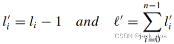
If ![]() is odd, we reduce the length of each side l i by one.Let
is odd, we reduce the length of each side l i by one.Let ![]() be the reduced lengths and
be the reduced lengths and ![]() be their summation, hence:
be their summation, hence:
如果![]() 是奇数,则每边的长度l i减1。假设
是奇数,则每边的长度l i减1。假设 ![]() 是减少后的长度,
是减少后的长度,![]() 是他们的和,则有:
是他们的和,则有:
和:

![]() which is the difference between two odd integers giving an even result. Thus
which is the difference between two odd integers giving an even result. Thus
![]() is even. A similar equation to calculate d i can be devised as follows:
is even. A similar equation to calculate d i can be devised as follows:
![]() 这是两个奇数之间的差,得到一个偶的结果。因此
这是两个奇数之间的差,得到一个偶的结果。因此![]() 是偶数。计算d i的类似公式如下:
是偶数。计算d i的类似公式如下:
![]()
In this case, instead of a vertex dislocation, we obtain an n-sided facet dislocation.
在这种情况下,我们得到的不是顶点位错,而是一个n边的小平面位错
This facet is formed by sparing one edge from each side l i, thus using ![]() instead to build the system of equation. 这个小平面是由每边l i保留一条边形成的,因此 使用
instead to build the system of equation. 这个小平面是由每边l i保留一条边形成的,因此 使用![]() 来建立方程组。
来建立方程组。
The facet is defined by 小平面的定义是
![]()
As such, for each i, there will be two rays emanating from G i and G i+1 meeting the corresponding side of the region at two points ![]() and
and ![]() with an in-between distance of 1. The region is then divided into 2n rectangular regions and one n-sided facet, as illustrated in Figures 4 and 5(b).
with an in-between distance of 1. The region is then divided into 2n rectangular regions and one n-sided facet, as illustrated in Figures 4 and 5(b).
同样的,对于每一个i, G i和G i+1发出的两条射线会在![]() 和
和![]() 点的区域对应的一侧,两者之间的距离为1。然后将区域划分为2n个矩形区域和一个n边小平面,如图4和图5(b)所示。
点的区域对应的一侧,两者之间的距离为1。然后将区域划分为2n个矩形区域和一个n边小平面,如图4和图5(b)所示。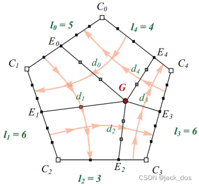
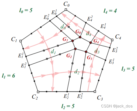
Figure 4: Examples of odd-sided regions where the total number of vertices on the boundary is even (top) and odd (bottom). The light red lines show the direction of the flow lines between the sides of the region.
图4:边界上顶点总数为偶数(左)和奇数(右)的奇数边区域的例子。浅红色的箭头线表示区域两边的流线的方向。
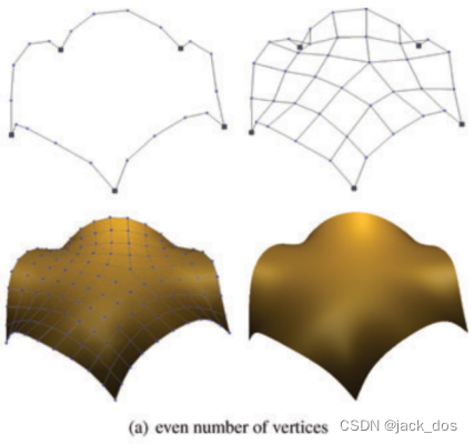
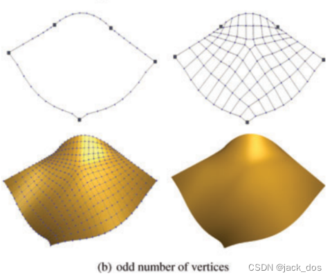
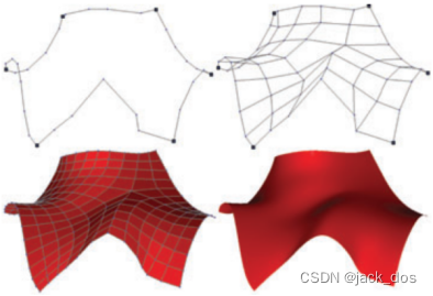
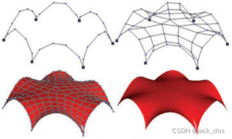
图5:边数为奇数的区域示例。对于每个子图:给定的折线(左上),构造网格(右上),一个Catmull-Clark细分(左下),以及相应的极限曲面(右下)。
• Case n is even当n是偶数时
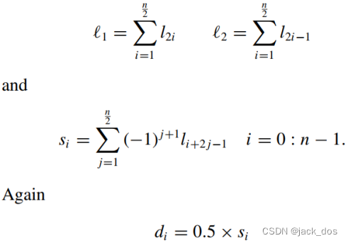
In this case, we assemble the lengths into two summations 1 and 2 as follows:
在这种情况下,我们将长度组装成两个求![]() 和
和![]() 的和,如下:
的和,如下:
In this case, s i is dependent on either 1 or 2. Consequently, we distinguish between the following cases:
在这种情况下,s i依赖于![]() 或
或![]() 。因此,我们区分以下情况:
。因此,我们区分以下情况:
1. If both![]() and
and ![]() are even then
are even then ![]() is integer.
is integer.
如果![]() 和
和![]() 都是偶数,则
都是偶数,则![]() 为整数。
为整数。
Again this yields the same result as the general solution. 这和通解得到的结果一样。
Thus, we obtain a set of n rectangular regions and an n-valent vertex dislocation [see Figures 6 and 7(a)].这样,我们得到一组n个矩形区域和一个n价顶点位错(见图6和图7(a))。
2. If both ![]() and
and ![]() are odd then we obtain a set of 2n rectangular regions and an n-sided facet dislocation. 如果
are odd then we obtain a set of 2n rectangular regions and an n-sided facet dislocation. 如果 ![]() 和
和![]() 都是奇数,那么我们得到了一个2n个矩形区域和一个n边小面位错的集合。
都是奇数,那么我们得到了一个2n个矩形区域和一个n边小面位错的集合。
The same solution follows as the case where n and ![]() were both odd (see Figures 6 and 7(c)).相同的解决方案与n和
were both odd (see Figures 6 and 7(c)).相同的解决方案与n和![]() 都是奇数的情况相同(参见图6和图7(c))。
都是奇数的情况相同(参见图6和图7(c))。
3. If ![]() is even and
is even and ![]() is odd, a length reduction by one is applied to the sides
is odd, a length reduction by one is applied to the sides ![]() contributing to the value of
contributing to the value of ![]() :
:
如果![]() 是偶数,
是偶数,![]() 是奇数,则对边
是奇数,则对边![]() 的长度减1,得到
的长度减1,得到![]() 的值:
的值:
![]()
Hence因此

And还有:
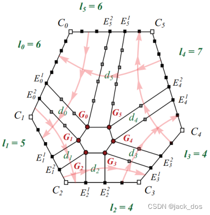
In this case, the vertex dislocation is replaced by an n/2-sided facet dislocation whose vertices are 5-valent vertex dislocations:
在这种情况下,将顶点位错替换为n/2边的面位错,其顶点为5价顶点位错:
A side with corners C i and C i+1 where (i = 2k + 1)1≤k≤ n2 is hit by a ray emanating from G k+1 at a vertex E i on this side.
角为C i和C i+1的边被从G k+1发出的射线击中在这条边的顶点E i处,其中(i = 2k + 1)1≤k≤ n2
As for a side with corners C i and C i+1 where (i = 2k)1≤k≤ n2 , two rays emanating from G k and
G k+1 contact the corresponding side in two points ![]() and
and ![]() . The region is then divided into 3n/2 rectangular regions and one n/2-sided facet dislocation, see Figures 6 and 7(b).
. The region is then divided into 3n/2 rectangular regions and one n/2-sided facet dislocation, see Figures 6 and 7(b).
对于一个角为C i和C i+1的边,其中(i = 2k)1≤k≤ n2,从G k和G k+1发出的两条射线在接触对应边后得到两个点![]() 和
和![]() 。然后将该区域划分为3n/2个矩形区域和1个n/2边的小面位错,见图6和图7(b)。
。然后将该区域划分为3n/2个矩形区域和1个n/2边的小面位错,见图6和图7(b)。
4. If ![]() is odd and
is odd and ![]() is even, the treatment is similar to the one described in the previous case.
is even, the treatment is similar to the one described in the previous case.
如果![]() 是奇数,
是奇数,![]() 是偶数,处理方法与前面的情况相似。
是偶数,处理方法与前面的情况相似。
(1) (2)
(3)
Figure 6: Examples of even-sided regions where the summations of the number of vertices on non-adjacent sides are both even (top), both odd (middle), or odd and even (bottom). The light red lines show the direction of the flow lines between the sides of the region.
图6:非相邻边的顶点数之和为偶数(a)、奇数(b)或奇数和偶数(c)的偶数边区域的例子。浅红色的线表示区域两边的流线的方向。
(a) ![]() 和
和![]() 都是偶数
都是偶数
(b) ![]() 是偶数,
是偶数,![]() 是奇数
是奇数
(c) ![]() 和
和![]() 都是奇数
都是奇数
Figure 7: Examples of regions with even number of sides. For each sub-figure: Given polylines (top left), constructed mesh (top right), one Catmull–Clark refinement (bottom left), and the corresponding limit surface (bottom right).图7:边数为偶数的区域示例。对于每个子图:给定的折线(左上),构造网格(右上),一个Catmull-Clark细分(左下),以及相应的极限曲面(右下)。
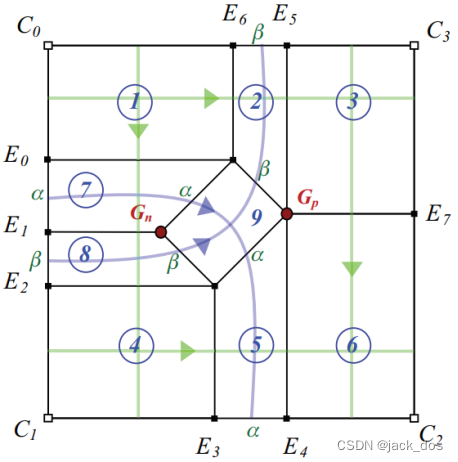
Figure 8: A quadrilateral region is divided into nine rectangular regions with two dislocations. The original flow lines of a rectangular region are shown in light green while the diamond shaped region redirects the flow lines in light blue. 图8:将一个四边形区域划分为9个具有两个位错的矩形区域。矩形区域的原始流线显示为浅绿色(①③④⑥处交叉的直线),而流线被菱形区域重定向,显示为淡蓝色(α和β处的两条曲线)。
4. Filling Quadrilateral Regions填充四边形区域
As mentioned in the previous section, the general framework algorithm cannot handle quadrilateral regions, i.e. 4-sided regions where opposite sides have different lengths.
如前一节所述,一般框架算法不能处理四边形区域,即对边长度不同的4边区域。
In this section, we describe how the proposed algorithm can be extended to fill such regions.
在本节中,我们将描述如何将所提出的算法扩展到填充这些区域。
The problem could be solved by using a refractor. 这个问题可以用折射镜来解决。
A refractor is a topological entity that redirects some flow lines and causes a deviation in their original direction of flow.
折射镜是一种拓扑实体,它可以改变某些流线的方向,使它们在原来的流动方向上发生偏移。
In the filling process, a set of four refractors formed in a diamond shaped setting are used to refract a subset of flow lines to adjacent instead of opposite sides.
在填充过程中,在菱形背景中形成的一组四个折射镜被用来将流线的子集折射到相邻而不是相反的边。
In what follows we describe the extension of the algorithm in detail.
在接下来的部分中,我们将详细描述算法的这个扩展。
4.1. The general solution 通用解决方案
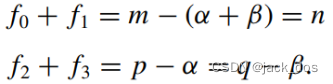
Let the lengths of the sides be as follows l 0 = m, l 1 = p, l 2 = n and l 3 = q.
假设有如下的长度l 0 = m, l 1 = p, l 2 = n, l 3 = q。
Without loss of generality, we assume that m > n and p > q.
为了不失一般性,我们假设m > n和p > q。
The filling algorithm creates two vertex dislocations, one negative G n and one positive G p, according to the basic structure given in Figure 8.
填充算法根据图8所示的基本结构创建了两个顶点位错,一个是负G n,一个是正G p。
This will determine the location of the refractor element and the rest of the mesh as follows:
这将确定折射元素和网格的其余部分的位置如下:
1.Without loss of generality, we can also assume that the difference between m and n is greater than that between p and q.
为了不失一般性,我们假设m和n之间的差异大于p和q之间的差异。
Let α and β be the number of flow lines refracting from the side of length m to its adjacent side of length p and to q, respectively.
假设α和β分别是从长度为m的边在长度p的邻边和q的邻边上的折射。
Thus the difference between m and n is α + β where α and β are defined by the following system: 因此m和n之间的区别是α+β,α和β是由以下系统:
![]()
We initially assume that ![]() is even, that is, α and β are integers.
is even, that is, α and β are integers.
我们先假设![]() 是偶数,即α和β是整数。
是偶数,即α和β是整数。
![]()
In the following section we study the special cases where k is odd and β is zero.
在接下来的部分中,我们研究下 k是奇数 和 β是零 的特殊情况。
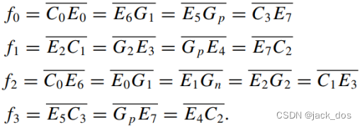
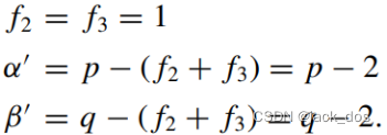
2. Let the four lengths f 0, f 1, f 2 and f 3 shown in Figure 9 be defined by
假设图9中的四个长度f 0, f 1, f 2, f 3有如下定义
3.Determine the location of the refractor and the points of contacts from the rays emanating from its vertices to the boundary sides.
确定折射器的位置和从它的顶点到边界边的射线的接触点。
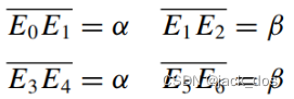
Let those vertices be E 0 , … , E 7, they are then determined by the following distances (see Figure 9): 假设那些顶点为E 0,…,E 7, 它们由以下决定(见图9):
Clearly, the distances显然
4. The quadrilateral region is then divided into 9 rectangular sub-regions as indicated in Figure8. 然后将四边形区域划分为9个矩形子区域,如图8所示。
Quad meshing is then a simple operation of grid generation as shown in Figure 10(a) illustrating
an example of integer values of α and β.
然后四边形网格是一个简单的网格生成操作,图10是一个α和β为整数的例子。
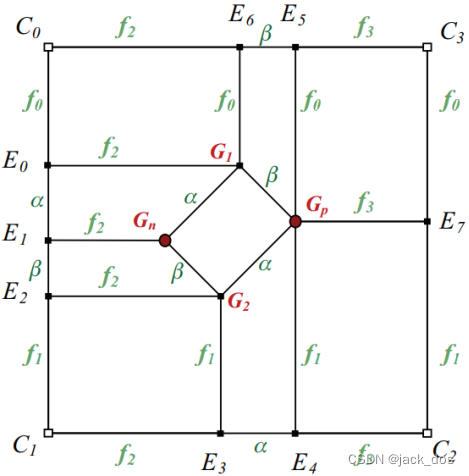
Figure 9: The lengths of the nine rectangular regions. 9个矩形区域的长度。
4.2. Non-integer solutions非整数解
The system used to find the values of α and β in Equation(8) may result in non-integer solutions if ![]() is odd. 如果
is odd. 如果![]() 是奇数,该系统用于查找方程(8)中α和β的值,可能会出现非整数的解。
是奇数,该系统用于查找方程(8)中α和β的值,可能会出现非整数的解。
In such a case, the system constructed to find α and β gives a solution of the form:
在这种情况下, α和β的值可如下算出:

The partitioning of the region is slightly modified as follows(see Figure 11):
区域的划分稍微做了如下修改(见图11):
a Merge regions 7 and 8 into one region. Consequently, E 1 and G n no longer exist;
将区域7和区域8合并到一个区域中。因此,E 1和G n不再存在;
![]()
We obtain 7 rectangular regions and one triangular(G 1 G 2 G p).
我们得到了7个矩形区域和1个三角形区域(G 1 G 2 G p)。
b Set the lengths of the following sides: 设置以下边的长度:
c Fill the 7 rectangular regions with quad elements. 用四边形填充7个矩形区域。
d Starting from G 1 towards G 2 on the largest side of the triangular region,
从G 1到G 2,在三角形区域的最大一侧,
let ![]() (respectively
(respectively ![]() ) lines flow to the side of length
) lines flow to the side of length ![]() (respectively
(respectively ![]() ).
).
假设![]() (分别
(分别![]() )条线流向长度为
)条线流向长度为![]() (分别
(分别![]() )的边。
)的边。
The lines cross at 4-valent vertices and produce a 3-sided facet dislocation at the side G 1G 2.这些线在4价顶点相交,并在侧G 1G 2处产生3边小平面位错。
The obtained partitioning, as illustrated in Figure 11, results in a positive 5-valent vertex dislocation, and a negative 3-sided facet dislocation, see Figure 10(b).
如图11所示,得到的划分结果为正5价顶点位错和负3边小面位错,见图10(b)。
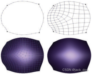
(a) α = 3, β = 2
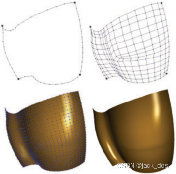
(b) α = 2.5, β = 1.5
(b) α = 2, β = 0
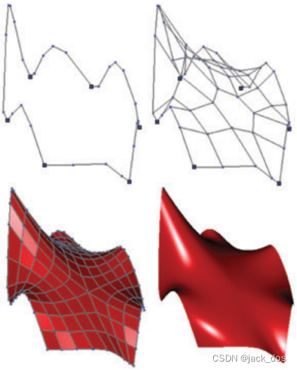
Figure 10: Examples of quadrilateral regions (see Section 4.1 for the definitions of α and β). For each subfigure: Given polylines (top left), constructed mesh (top right), one Catmull–Clark refinement (bottom left), and the corresponding limit surface (bottom right).四边形区域的例子(见4.1节定义的α和β)。对于每个子图:给定的折线(左上)、构造的网格(右上)、一个Catmull-Clark细分(左下)和相应的极限曲面(右下)。
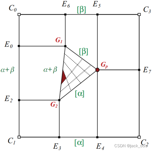
Figure 11: An example of a quadrilateral region where the number of vertices is odd. The resulting mesh has a 5-valent dislocation and a three-sided facet.
图11: 一个顶点数为奇数的四边形区域的例子。由此产生的网格有一个五价位错和一个三边面。
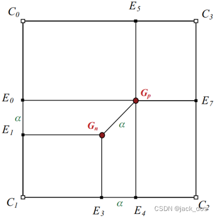
Figure 12: An example where the mismatch between opposite sides are similar. Using one refractor, a quad mesh is generated with two dislocations.
图12:在一个例子中,相对两边的不匹配是相似的。使用一个折射镜,一个四元网格产生了两个位错。
Furthermore, when the length difference, say p − q, between two opposite sides is identical to the difference m − n between the other two sides, the system assigns β a zero value.
此外,当长度不同时,比如p−q, 在两个相对的边之间,等于另两个边之间的差m−n, 系统将β赋值为零。
In this case regions 2, 8, and 9 collapse and the region is partitioned into 6 rectangular regions (see Figures 12 and 10(c)).
在本例中,区域2、8和9折叠,并将区域划分为6个矩形区域(参见图12和图10(c))。
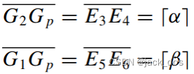
Figure 13: A quadrilateral region where p − α = q − β < 0.
图13:四边形区域: p−α = q−β < 0。
4.3. Higher distortion solutions高畸变的解决方案
The algorithm that fills a quadrilateral region uses 2 dislocations to generate a quad mesh with a minimum total distortion of 2.
该算法使用2个位错来生成一个总失真最小为2的四边形网格来填充一个四边形区域。
This meshing is based on redirecting flow lines from opposite to adjacent sides.
这种网格划分是基于将流向线从对边重定向到相邻边。
When the difference between one couple of opposite sides is larger than the total length of the other couple (see Figure 13), an alternative way must be devised.
当一对相对的边之间的差值大于另一对的总长度(见图13)时,必须设计一种替代方法。
Since we have a lower bound for f 0 and f 1(l 2 = n ≥ 2), the distances that may need special treatment are f 2 and f 3.
因为我们有一个f 0和f 1的下界(l 2 = n≥2),可能需要特殊处理的距离是f 2和f 3。
Null or negative values for f 2 or f 3 may be considered as special cases where: p − α = q − β ≤ 0
当p − α = q − β ≤ 0时,f 2或f 3的空值或负值,可视为特殊情况:
In such situations, i.e. where f 2 + f 3 < 0, we propose splitting the region into two parts.
在这种情况下,即f 2 + f 3 < 0时,我们建议将区域分成两部分。
The polyline that splits the region has M (a vertex on the side C 0C 1) and E 7 as its extremities (see Figure 14). 分割区域的折线的末端是M (C 0C 1边上的一个顶点)和E 7(参见图14)。
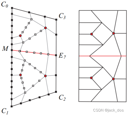
Figure 14: The region shown in Figure 13 is filled by a mesh with a total distortion of 4 (α´= 3, β´= 1, and δ = 8).图14:图13中的该区域被填充成一个总畸变为4的网格(α´= 3, β´= 1, δ = 8)
The selection of M and the number of vertices generated on the side M E 7 guarantee that the resultant quad mesh has a total distortion of 4.
M的选择和边M E7上生成的顶点数保证生成的四元网格的总失真为4。
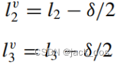
To begin with, we force f2 and f3 to both have the minimal positive value 1 and find alternative values α´ and β´ instead of α and β, respectively. Thus:
一开始,我们强制f 2 和 f 3都为最小值1,分别找到α和β的替代值α´和β´。因此:
We then define δ = (α + β) − (α+ β).然后,我们定义 δ = (α + β) − (α´ + β´).
Now M is located f 0 + β´+ δ/2 away from C 0. 现在,M 位于距离C 0的 f 0 + β´+ δ/2 处。
The number of vertices generated on the side ME 7 is δ/2 + 1 and thus:
M E 7边上生成的顶点数为δ/2 + 1, 因此:

The quadrilateral region initially defined by the corners: C0, C1, C2, and C3 is now split into two regions defined by 最初由角定义的四边形区域: C0, C1, C2, C3现在被分割成两个区域
1. C0, M, E7, and C3
2. M, C1, C2, and E7
Having this configuration (see Figures 14 and 15), the two new quadrilateral regions can be filled with a sub-total distortion of 2 each, yielding a total distortion of 4 in the initial region.
有了这种配置(参见图14和图15),两个新的四边形区域就可以用每个区域的次总失真度为2来填充,从而使初始区域总失真度为4。
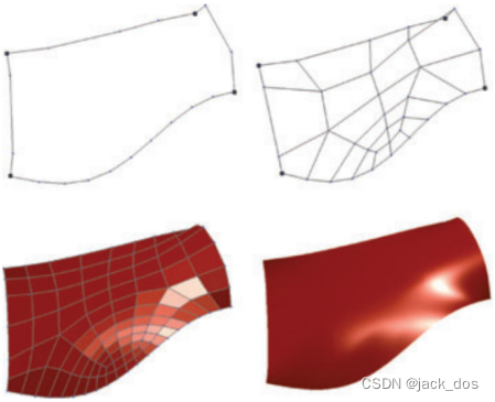
Figure 15: An Example of a four sided region filled by a quad mesh with a total distortion of 4. 图15:一个四边区域的例子,由一个总变形为4的四面网格填充。
5. The Geometrical Phase几何阶段
Since the topological phase determines a partitioning to rectangular regions, the geometrical problem reduces to finding the geometric position of the vertices of the generated mesh.
由于拓扑阶段决定了矩形区域的划分,几何问题简化为寻找生成网格的顶点的几何位置。
Typically, the quality of the resulting mesh could possibly be improved by employing any of the existing fairing techniques, 通常情况下,网格的质量可以通过使用现有的整流罩技术来提高,
such as those used in physically-based modelling, energy minimization, or any other scheme based on curvature flow [YI99].
例如那些用于基于物理的建模,能量最小化,或任何其他基于曲率流的方案[YI99]。
Our geometric phase is based on generalizing discrete Coons introduced in [FH99].
我们的几何阶段是基于[FH99]中介绍的一般化离散孔斯。
The Coons construction normally gives good quality results cheaply and could be used as a good starting point for iterative fairing, minimizing variation of curvature if desired.
孔斯结构通常可以很容易就得到质量比较好的结果,并可作为迭代整流罩的良好起点,如果需要,尽量减少曲率的变化。
Initially, we determine the locations of the vertices on the flow lines bounding the subregions,
首先,我们确定了在子区域边界上的流线上的顶点的位置,
these are the rays emanating from the dislocations and landing on the given polylines.
它们来自位错所发出的射线并落在给定的折线上。
Once these vertices are determined, the interior vertices of each of the subregions could be easily computed using discrete Coon’s patches.
一旦这些顶点被确定,使用离散孔斯曲面片,可以很容易的计算出每个子区域的内部顶点。
The essential part is then how to determine the position of the dislocations.
关键是如何确定位错的位置。
We distinguish between the two cases: nonquadrilateral and quadrilateral regions.
我们区分了两种情况:非四边形区域和四边形区域。
In the following, we explain how to compute the positions of these dislocations,
下面,我们将解释如何计算这些位错的位置,
and after that the remaining vertices of the region could be easily computed.
然后可以轻松地计算该区域的其余顶点。
5.1. Dislocations in non-quadrilateral regions 非四边形区域的位错
For a non-quadrilateral region, the geometric position of a vertex dislocation can be estimated as follows:
对于非四边形区域,顶点位错的几何位置估计如下:
- Let Ei and Ei+1 be the points of contact at which the rays from the dislocation G meet the sides of the corner Ci.
设Ei和Ei+1为位错G的射线与角Ci的边的接触点。
- We construct a rectangular region Ei-1,C i,Ei,G. 我们构造一个矩形区域Ei-1, C i, E i, G。
Let us denote by a i its logical area. 假设我们用a i来表示它的逻辑区域。
The logical area of a region defined by four vertices 一个由四个顶点定义的区域的逻辑区域
is considered here to be the number of quad elements in the parallelogram or the rectangular region defined by these vertices.
在这里被认为是平行四边形中的四元数或由这些顶点定义的矩形区域。
3. Using the geometry of the edges of the parallelogram defined by the three corners, we can compute an estimate of the position of the dislocation G by: 利用由三个角定义的平行四边形的边的几何性质,我们可以通过以下方法计算出错位位置G的估计值:
Ei + Ei-1 - Ci.
4. The step above is repeated n times, one for each corner, giving n estimators of G.
上面的步骤重复了n次,每个角一个,给出了G的n个估计量。
We then take a weighted mean of the these estimators using weights inversely proportional to the area of the parallelogram. 然后,我们使用与平行四边形面积成反比的权值对这些估计量取加权平均值。
Accordingly the vertex will be given by:因此,顶点将由下面公式给出:
5.2. Dislocations in quadrilateral regions
Finding the position of dislocations in quadrilateral region is not straightforward.
在四边形区域中寻找位错的位置不是一件容易的事情。
The problem can be summarized as calculating the position of a vertex dislocation by relating it to every corner C i of the region and associate this relation with the appropriate edge vertices Ei and the areas of the corresponding subregions.
该问题可以归结为计算一个顶点位错的位置,通过将其与区域的每个角C i联系起来,将这种关系与适当的边顶点Ei和相应的子区域的区域联系起来。
Details of the solution of every case will stretch this section needlessly.
每个案例的解决方案的细节将不必要地延伸本节。
We limit our discussion to the case of the quadrilateral region described in Section 4.1 and find the location of G p . 我们只讨论4.1节中描述的四边形区域的情况,并找到G p的位置。
The solutions in other configurations could follow a similar approach.
其他配置中的解决方案可以采用类似的方法。
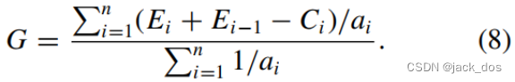
The four estimators of G p corresponding to the four corners are as follows (see Figures 8 and 9):
四个角对应的G p的四个估计量如下(见图8和图9):
1. (E1 + E5 - C 0) with weight (a1 + a2 + a7 + a9)-1,
2. (E1 + E4 - C 1) with weight (a4 + a5 + a8 + a9)-1,
3. (E4 + E7 - C 2) with weight (a6)-1,
4. (E5 + E7 - C 3) with weight (a3)-1,
Where the (ai) are the corresponding logical areas of the nine subregions.
其中(ai)为9个子区域对应的逻辑区域。
5.3. Remaining vertices剩余的顶点
Once the position of the dislocation is computed, the vertices on the rays emanating from it to the sides of the region can be constructed using discrete Coon’s patches.
一旦计算出位错的位置,就可以使用离散孔斯补片来构造出从它向该区域边缘发射的顶点。
To begin with, we denote by ![]() the vertex on ray i which is at distance j(1 < j < d i) away from Ei and d i - j away from G (see Figure 16). 首先,我们用
the vertex on ray i which is at distance j(1 < j < d i) away from Ei and d i - j away from G (see Figure 16). 首先,我们用![]() 表示射线i上的顶点,它与Ei之间的距离为j(1 < j < d i),与G之间的距离为d i - j (见图16)。
表示射线i上的顶点,它与Ei之间的距离为j(1 < j < d i),与G之间的距离为d i - j (见图16)。
Let ![]() and
and ![]() be the counterpart vertices of
be the counterpart vertices of ![]() on the sides i - 1 and i + 1, respectively.
on the sides i - 1 and i + 1, respectively.
设![]() 和
和![]() 分别是
分别是![]() 在i - 1和i + 1两边的对应顶点。
在i - 1和i + 1两边的对应顶点。
We then consider the rectangular subregion that represents the boundaries of the discrete Coon’s patch defined by the four corners Ei-1, C i, C i+1, and Ei+1,
然后我们考虑矩形子区域可以由四个角:Ei-1, C i, C i+1, Ei+1所定义的离散孔斯补片的边界来表示,
assuming that the polyline connecting Ei-1, G, and Ei+1 is considered as one side of the patch.
假设折线Ei-1, G, 和Ei+1是补片的一条边。
The four counterpart vertices of ![]() are then:
are then: ![]() 的四个对应顶点为:
的四个对应顶点为:
1. ![]() on the side Ei-1 C i,
on the side Ei-1 C i,
2. Ei on the side C i C i+1,
3. ![]() on the side C i+1 Ei+1,
on the side C i+1 Ei+1,
4. G on the side Ei+1 Ei-1.
Using the formula in [FH99], we then calculate all the vertices on the rays emanating from the dislocations.
使用[FH99]中的公式,然后我们计算从位错发出的射线上的所有顶点。
After that, the interior vertices of the n subregions defined by (G, Ei, C i, Ei+1) are computed.
然后由(G, Ei, C i, Ei+1)定义的n个子区域的内部顶点就可以被计算出来了。
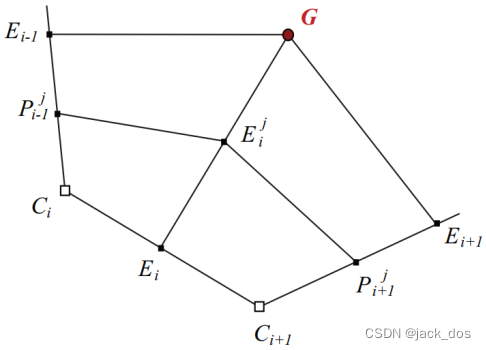
Figure 16: The rectangular region involved in locating ray vertices.
图16:定位射线顶点所涉及的矩形区域。
6. Discussion and Limitations讨论和局限性
Our filling algorithm system was implemented where Figures 5–15 show a variety of holes with different boundary configurations, their corresponding generated meshes, and limit surfaces.
我们的填充算法系统实现在图5-15中显示的不同边界组成的各种孔,及其相应生成的网格和极限曲面。
The surfaces are Catmull–Clark subdivision surfaces but the meshes could be used for any quad-based subdivision scheme.
这个面是Catmull–Clark细分曲面,但网格可以用于任何基于四元组的细分方案。
As mentioned in the previous section, our proposed algorithm creates meshes with a maximum of one n- valent vertex dislocation in most cases, and with a total distortion of n − 4; that is achieving the minimum distortion.如前一节所述,我们提出的算法可以在大多数情况下创建这样的网格:最多有一个n价顶点位错,总失真为n−4;这是最小失真的一种实现方式。
For certain cases with n even, the algorithm creates n/2 5-valent vertex dislocations and an n/2-sided dislocation facet. The total distortion is then:
对于n为偶数的某些情况,该算法会产生n/2个5价顶点位错和n/2边的位错小平面。总失真为:
Considering that the n/2-sided facet adds |n/2 − 4| distortion.
考虑到n/2边的小平面增加了|n/2−4|的失真。
In the case where n/2 > 4, we have 在n/2 > 4的情况下,我们有
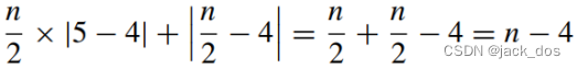
where |n − 4| is the lower bound of distortion in an n-sided mesh. 其中|n−4|是n边网格中畸变的下界。
Therefore, the algorithm tends to also minimize distortion in the created mesh.
因此,该算法也倾向于创建网格中时的最小化的失真。
This minimum distortion solution is valid as long as all computed logical distance are nonnegative.
这个最小失真解是有效的,只要所有计算的逻辑距离都是非负的。
In some situations, the lengths of certain sides are relatively too large, causing negative values of the distances from the dislocation to that side (See Figure 17).
在某些情况下,某些边的长度相对过大,导致从位错到该边的距离为负值(见图17)。
The following indicates when such situations are encountered:
当遇到这种情况时,如下所示:
1.If the region is 3-sided, then all solutions are positive iff the lengths of its sides obey the triangle inequality: 如果区域是3边的,当且仅当它的边长遵循三角形不等式时,所有解都为正数
li + li+1 ≥ li+2 i = 1 : 3
2. With five-sided regions, the necessary and sufficient condition for a minimal distortion solution is to have the sum of the length of any two adjacent sides less than the sum of the other three, thus:
对于五边区域,最小变形解的充要条件是任意两个相邻边的长度之和小于其他三个边的长度之和,即:
li + li+1 ≤ li+2 + li+3 + li+4
3. For n-sided regions with odd n (a similar approach may be followed for even n), we present another form of Equation (5) as follows:对于n为奇数的n边区域(对于偶数n也可以采用类似的方法),我们将式(5)的另一种形式表示为:
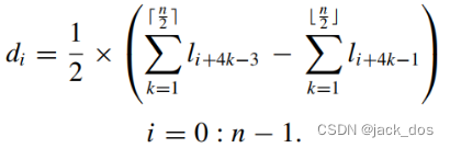
Thus if for some i the sum of the lengths of the sides with indices:
因此对于某些i,如果边的长度索引总和:
is greater than the sum of the other n/2, 大于其他n/2之和,
the region cannot be filled with the minimal distortion quad mesh.
那么该区域就不能用最小失真四元网格来填充。
Refractors can be used to get rid of negative distances by reducing the high density of the sides causing such solutions. 通过降低边的高密度,折射可以用来避免产生这种解的负的距离。

Figure 17: An example where the distance from the dislocation to the side with extremities C0 and C1 is negative (d 0 = -1, d 1 = 2, d 2 = 4, d 3 = 6, d 4 = 2).
一个例子,在这个例子中,从位错到有C0和C1的一侧的距离为负
The sides causing the negative results could be identified using the above formula.
用上述公式,这些边可能产生一些负的结果。
For instance, in the example shown in Figure 17, the sides causing d0 to be −1 are l2 and l3.
例如,在图17所示的例子中,使d0为−1的边是l2和l3。
To avoid having the dislocation on the boundary, we set d0 to 1 and thus the negative term in the above formula is reduced by δ = 4, where δ = (1 - d0) × 2
为了避免边界上的位错,我们d0设置为1, 因此在上述公式中当δ = (1 - d0) × 2时,通过设置δ= 4来减少负值的出现
This value is to be distributed over l2 and l3. The system is reset to the initial lengths having virtual values for l2 and l3: 这个值要在l2和l3上分布。系统复位到初始长度,l2和l3的虚拟值为:
The new region lengths become: ![]() , giving positive new distances as shown in Figure 18. 新的区域长度为:
, giving positive new distances as shown in Figure 18. 新的区域长度为: ![]() ,给出正的新距离,如图18所示。
,给出正的新距离,如图18所示。
The refractor’s role is to create a channel to redirect a beam of δ/2 flow lines to depart from l2 and land on l3 (see Figure 18).
折射的作用是创建一个通道:重定向这个由δ/ 2条从l2射向l3的流线所组成的光束 (参见图18)。
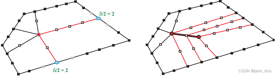
Figure 18: Using the refractor to fill the region with a quad mesh of total distortion = |6 − 4| + |3 − 4| = 3.
图18:使用折射镜,用四重网格填充区域,总变形 = |6−4| + |3−4| = 3。
7. Conclusions and Future Work结论与未来工作
The proposed filling algorithm provides a coherent approach for generating control meshes of holes bounded by a set of polylines.
我们所提出的填充算法,为”由一组折线为边界” 所组成的孔生成控制网格,提供了一种连贯的方法。
The meshes are quad-based, having as smooth flow as possible, and with a minimum total distortion of its vertices.
网格是基于四边形的,具有尽可能平滑的,并且其顶点的总失真最小的特点。
As such, they could be integrated in any quadrilateral subdivision scheme with less artefact, typically caused by dislocations.
因此,它们可以集成在任何四边形细分方案,通常是由错位造成的。
Because the topological and geometrical information are only generated from the given polylines vertices, 由于拓扑和几何信息都是由给定的多边形顶点生成的,
the approach generalizes rectangular discrete Coon’s patches to n-sided patches.
因此该方法可以将矩形离散孔斯曲面概括成n边补片。
Furthermore, it is extended to handle rectangular discrete Coon’s patches defined by non-matching density of boundary vertices.
而且,可以将其推广到处理由边界点所组成的非匹配密度定义的矩形离散孔斯补片。
The boundaries of a hole are B-spline curves of their corresponding polygons.
孔的边界是相应多边形的b样条曲线。
They are of degree inferred by the subdivision scheme employed: 它们的程度由细分方案来推断:
that is cubic B-spline in the Catmull–Clark setting, or quadratic B-spline in the Doo–Sabin setting.
在Catmull-Clark设置中是三次b样条,在Doo–Sabin设置中是二次b样条。
If we replace each of these polylines by a polygonal complex such as [Nas00, NA02, Nas03]
如果我们将每一条折线都替换成多边形,例如[Nas00, NA02, Nas03]所提到的,
then the limit surface of the filled holes will interpolate their corresponding curves.
那么所填孔的极限曲面都将对其相应的曲线进行插值。
In the Doo–Sabin setting, it should be possible to construct n holes sharing a non-4-valent corner
在Doo–Sabin设置中,应该有可能构建n个孔共享一个非4价角,
at which n curves could be interpolated with cross tangent boundary conditions.
在这个角上,n条曲线可以通过交叉切线边界条件进行插值。
A similar solution in the cubic case is still under investigation but with cross curvature conditions along the interpolated curves.
类似的解决方案仍在调查中,但有在插值曲线上的交叉曲率条件下。???
As for the types of holes, since the vertices of the generated meshes are linear combinations of the given boundary vertices, the algorithm could mainly handle convex holes.
对于孔的类型,由于生成网格的顶点是给定边界顶点的线性组合,因此该算法主要可以处理凸孔。
A concave hole, such as an L-shaped one, could be handled by completing it with virtual boundaries that makes it convex, and then use edge collapsing to remove the unnecessary part.
对于像L状的凹孔,可以通过虚拟边界使其凸出来完成,然后使用边缘折叠来去除不必要的部分。
This will also be investigated in future work.这也将在今后的工作中进行研究。
Finally, future work could also include experimenting with a 4-sided hole with various edge length differences to examine the number of extraordinary vertices or degenerate quads generated.
最后,未来的工作可能还包括实验一个具有各种边长差异的4边孔,以检查生成的非规则顶点数量或简化四边形的生成。
Acknowledgements致谢
Ali Charara worked on the implementation of an early version of this algorithm back in 2005. His efforts are greatly appreciated. Thanks are also due to Khalid Sinno for reimplementing part of the solution in the odd case. Their feedback helped us in implementing the complete system presented in this paper.
Ali Charara早在2005年就致力于实现该算法的早期版本。他的努力受到极大的赞赏。感谢Khalid Sinno在奇怪的情况下重新实现了部分解决方案。他们的反馈帮助我们实现了本文提出的完整系统。
参考文献(略)


 321
321


 被折叠的 条评论
为什么被折叠?
被折叠的 条评论
为什么被折叠?
 到【灌水乐园】发言


