


一、FPGA multiboot有什么用
FPGA Multiboot是一种允许FPGA在运行时动态切换不同配置映像(bitstream)的功能,其主要作用和应用场景如下:
-
容错与可靠性
安全回退(Fallback):
当主配置映像(如新升级的固件)出现故障时,FPGA可自动回退到预存的黄金映像(Golden Image),确保系统持续运行,提高容错能力。
看门狗超时触发:
如果主映像运行异常(如逻辑死锁),看门狗定时器可触发Multiboot,强制加载备份映像。 -
动态重配置
多功能切换:
在不重启FPGA的情况下,切换不同的硬件功能。 -
远程升级(Remote Update)
安全更新:
通过网络远程更新FPGA配置,若新映像失败,自动回退到旧版本,避免“变砖”风险。
二、Xilinx multiboot原理
参考Xilinx xapp1247和1257, 7 Series和UltraScale的multiboot原理相同,只是实现方法有所差异。
注:本文描述仅参考 xapp1247和1257描述了包含2个image 的SPI fallback功能,Xilinx还提供了更多image的动态配置功能,本文不再描述。
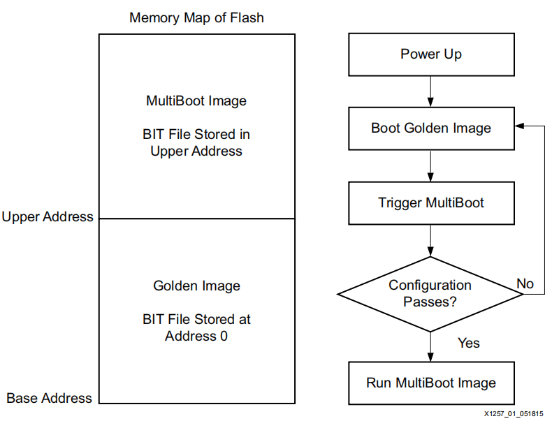
如下图所示,multiboot分为两个image空间,一个Gloden Image,为基础镜像空间,在异常时刻返回该空间,Gloden Image其实地址为0,并且存储有Upper Address信息,FPGA在启动时首先从0地址加载,在检测到有跳转地址Upper Address后,直接跳转到Upper Address执行。
&emspMultiboot Image为实际需要运行的镜像空间,在执行该空间bit失败后,可自动跳转到该空间。跳转的条件有:
• IDCODE error
• Cyclic redundancy check (CRC) error
• Watchdog timer timeout error
&emsp同时Gloden Image后还可以附加一个看门狗计数器,在Multiboot Image加载超时后自动跳转到Gloden Image(该功能xapp文件未列出,可参考UG470和UG570 Configuration文件)
三、multiboot实现方法
1.通过xdc约束是在bit流中加入Upper Address等相关信息,7 Series和UltraScale系列约束文件有所不同。
2.采用ICAPE原语,7Series采用ICAPE2,UltraScale采用ICAPE3。
3.1 7Series xdc multiboot实现方法
在Gloden Image重增加以下约束:
set_property BITSTREAM.CONFIG.CONFIGRATE 33.0 [current_design]
set_property BITSTREAM.CONFIG.CONFIGFALLBACK ENABLE [current_design]
set_property BITSTREAM.CONFIG.NEXT_CONFIG_ADDR 0x0400000 [current_design]
set_property BITSTREAM.GENERAL.COMPRESS TRUE [current_design]
set_property BITSTREAM.CONFIG.SPI_BUSWIDTH 1 [current_design]
在Multiboot Image重增加以下约束:
set_property BITSTREAM.CONFIG.CONFIGRATE 33.0 [current_design]
set_property BITSTREAM.CONFIG.CONFIGFALLBACK ENABLE [current_design]
set_property BITSTREAM.GENERAL.COMPRESS TRUE [current_design]
set_property BITSTREAM.CONFIG.SPI_BUSWIDTH 1 [current_design]
其中Multiboot Image起始地址为0x0400000,可根据实际需求设置
需要注意的是:
(1)当flash空间在256MB以上,需使能SPI_32BIT_ADDR ,否则可不使能
(2)7 系列默认SPI模式为X1,如配置了其他模式,需改为默认模式,fallback仅支持SPIX1模式。。
(3)COMPRESS根据需求设置,如不开启bit压缩,bit空间更大
3.2 UltraScale xdc multiboot实现方法
在Gloden Image重增加以下约束:
set_property BITSTREAM.CONFIG.CONFIGRATE 51.0 [current_design]
set_property BITSTREAM.CONFIG.NEXT_CONFIG_ADDR 0x0400000 [current_design]
set_property BITSTREAM.CONFIG.NEXT_CONFIG_REBOOT ENABLE [current_design]
set_property BITSTREAM.CONFIG.SPI_32BIT_ADDR YES [current_design]
set_property BITSTREAM.CONFIG.SPI_BUSWIDTH 4 [current_design]
set_property BITSTREAM.GENERAL.COMPRESS TRUE [current_design]
在Multiboot Image重增加以下约束:
set_property BITSTREAM.CONFIG.CONFIGRATE 51.0 [current_design]
set_property BITSTREAM.CONFIG.CONFIGFALLBACK ENABLE [current_design]
set_property BITSTREAM.CONFIG.SPI_32BIT_ADDR YES [current_design]
set_property BITSTREAM.CONFIG.SPI_BUSWIDTH 4 [current_design]
set_property BITSTREAM.GENERAL.COMPRESS TRUE [current_design]
3.3 xdc 增加watchdog 方法
在Gloden Image重增加以下约束:
set_property BITSTREAM.CONFIG.TIMER_CFG 32'h0989680 [current_design]
watchdog计数器设置值与cclk相关,计数器时钟频率为cclk/256,如cclk配置为51MHz,计数器设置为32’h0989680,则watchdog超时时间为32’h0989680*256/51000000=50s.
watchdog的fallback流程如下图所示:
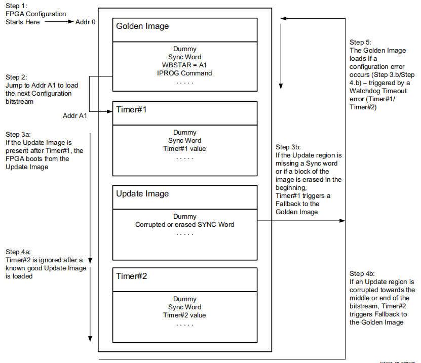
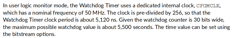
注:通过以上配置在AU5P上实测watchdog 大概5秒超时,具体原因未知。下图是ug570中watchdog计数器的描述,最大位宽为30bit。
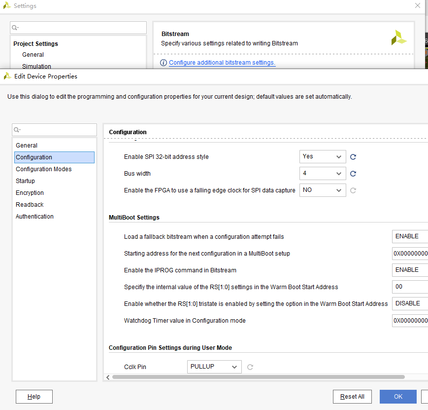
以上配置也可通过UI界面配置,最终存储到xdc文件内,需要在在打开实现后再bitstream 设置中打开configure additionat bitstream bitstream设置
3.4 multiboot mcs烧写文件生成
可通过Vivado中的tools中的Generate Memory Config File UI界面执行。其中通过2个bit生成mcs文件,也可生成为bin文件。Gloden.bit其实地址为0,Updata.bit起始地址为0x400000,与Gloden Image中定义的NEXT_CONFIG_ADDR地址匹配即可。
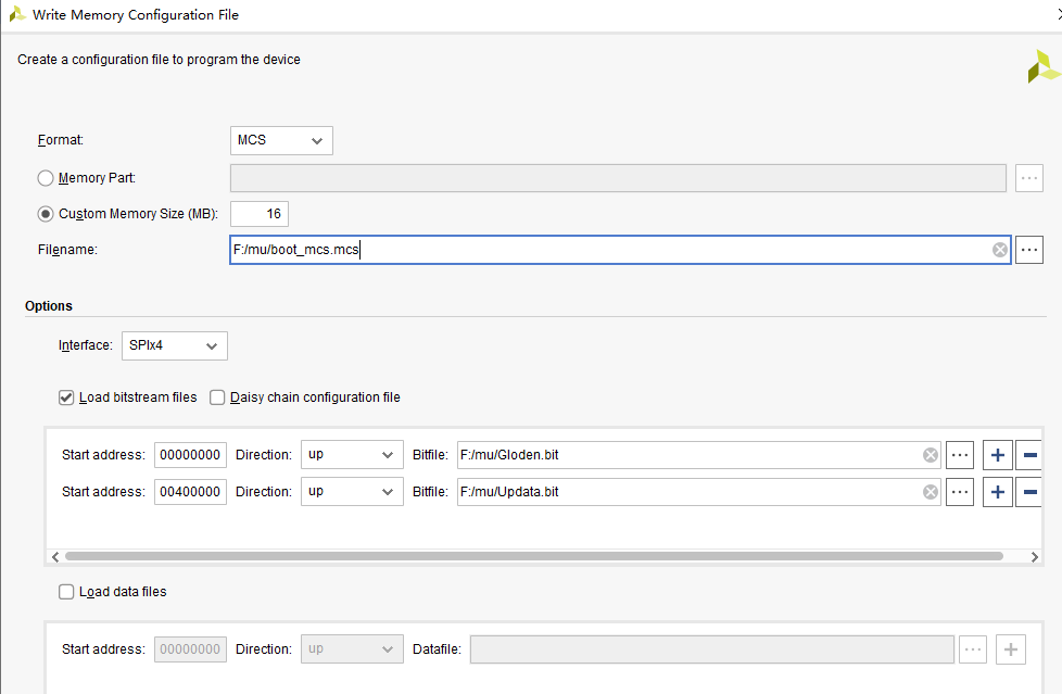
也可通过tcl命令:
write_cfgmem -format mcs -size 16 -interface SPIx4 -loadbit {up 0x00000000 "F:/mu/Gloden.bit" up 0x00400000 "F:/mu/Updata.bit" } -force -file "F:/mu/boot_mcs.mcs"
3.5 multiboot 中updata 烧写文件生成
在完成Gloden Image和Multiboot Image烧写后,需要更新Multiboot Image中的内容,则将Multiboot Image工程生成的bit/bin文件烧写到0x400000所在起始地址即可,烧写方法:
(1)可采用FPGA逻辑生成flash烧写功能,电脑通过网口或串口等将bit或bin文件传输到FPGA,FPGA烧写到flash对应空间;
(2)采用Vivado JTAG烧写,需将Multiboot Image工程生成的bit文件转为mcs文件,起始地址设置为0x400000
四、FLASH SPI在线升级
参考链接:FLASH SPI在线升级
参考文件
xapp1257-multiboot-fallback-spi-flash.pdf
xapp1247-multiboot-spi
ug570-ultrascale-configuration
ug470_7Series_Config


 被折叠的 条评论
为什么被折叠?
被折叠的 条评论
为什么被折叠?
 到【灌水乐园】发言


