


这是一个非常小的技术点,本拟放在另外一篇文章中介绍,但考虑到其相对独立性,因此独立成篇。
当osgEarth的earth文件中将map的type设置为"projected"时,将以二维形式显示地球,可用于表现二维态势。
一、时变对象
在态势系统中,存在道路、城市等基本固定的二维对象,即传统上采用点、线、面表示的GIS数据,这些可以通过earth文件或者编码进行加载显示即可。
osgEarth对于点、线、面对象提供支持,如从一个矢量文件中加载线对象
void AddVector(osg::ref_ptr<osgEarth::Map> map){
	std::string filePath = "world.shp";
	osgEarth::Drivers::OGRFeatureOptions featureData;
	featureData.url() = filePath;
	osgEarth::Features::FeatureSourceLayerOptions ogrLayer;
	ogrLayer.name() = filePath + "_source";
	ogrLayer.featureSource() = featureData;
	osgEarth::Features::FeatureSourceLayer*  featureSourceLayer = new osgEarth::Features::FeatureSourceLayer(ogrLayer);
	map->addLayer(featureSourceLayer);
	osgEarth::Features::FeatureSource *features = featureSourceLayer->getFeatureSource();
	osgEarth::Symbology::Style style;
	osgEarth::Symbology::RenderSymbol* rs = style.getOrCreate<osgEarth::Symbology::RenderSymbol>();
	rs->depthTest() = false;
	osgEarth::Symbology::LineSymbol* ls = style.getOrCreateSymbol<osgEarth::Symbology::LineSymbol>();
	ls->stroke()->color() = osgEarth::Symbology::Color("#ffff00");
	ls->stroke()->width() = 1.0;
	ls->tessellationSize()->set(100, osgEarth::Units::KILOMETERS);
	osgEarth::Features::FeatureModelLayerOptions fmlOpt;
	fmlOpt.name() = filePath;
	fmlOpt.featureSourceLayer() = filePath + "_source";
	fmlOpt.enableLighting() = false;
	fmlOpt.styles() = new osgEarth::Symbology::StyleSheet();
	fmlOpt.styles()->addStyle(style);
	osg::ref_ptr<osgEarth::Features::FeatureModelLayer> fml = new osgEarth::Features::FeatureModelLayer(fmlOpt);
	map->addLayer(fml);}
但在一个完整的态势系统或者仿真系统中,除了静态对象外,往往还存在大量动态的、几何数据随时间改变的对象,如车辆、飞机等点对象,车船飞机轨迹等线对象,卫星覆盖、传感器探测等面对象。称这些位置几何数据随时间改变的对象为时变对象。
二、采用osgEarth预定义类型绘制时变对象
对于动态对象,osg中可以定义一个回调类模板
template <class T>
class UpdateCallbackTemplate :public osg::NodeCallback{
public:
	UpdateCallbackTemplate() {};
	virtual void operator()(osg::Node* node, osg::NodeVisitor* nv) {
		osg::ref_ptr<T> obj = dynamic_cast<T*>(node);
		obj->update();	};};
在对应的对象中,构造函数中创建osgEarth点、线、面对象,在对应回调接口函数进行数据更新。
SatelliteTrajectory2D::SatelliteTrajectory2D(Satellite* sat){
	......
addUpdateCallback(new UpdateCallbackTemplate<SatelliteTrajectory2D>);}
上述代码最后一行是利用前述类模板示例化一个相应类,该类必须实现update函数,来进行几何数据的更新。
void	SatelliteTrajectory2D::update(bool force){
	QVector<CPoint3D>* pts = _satellite->getECFpts();
	_feature->getGeometry()->clear();
	for (int i = 0; i < pts->size(); i++)	{
		double H, L, B, x, y, z;
		DD2LB(pts->at(i).x, pts->at(i).y, pts->at(i).z, B, L, H);
		LB2DD(B, L, 0, x, y, z);
		_feature->getGeometry()->push_back(osg::Vec3d(L,B,0));	}
	_featureNode->dirty();}
上述方法存在的突出问题是效率,对于点对象基本影响不大,但实时更新线对象特别是面对象的几何数据将导致系统效率急剧下降。此外,在开发过程中,回调函数曾导致程序崩溃以至于不得不通过timer来调用,但具体何种情况导致的已无记录,因此仅在此处做一提示。
三、采用osg几何对象绘制时变对象
事实上,采用osg中几何对象绘制三维态势时并未出现效率下降。效率下降应该主要是osgEarth的点、线、面对象生成中的大量运算或调用所导致。因此,采用osg中的几何对象绘制线、面对象即可,其核心主要是几行代码
std::vector<osg::Vec3d> pts0;
	generateLBs(pts0);
	GeoExtent extent(SpatialReference::create("wgs84"), -180, -90, 180, 90);
	const SpatialReference* featureSRS = extent.getSRS();
	const SpatialReference* outputSRS = Application::_mapNode2D->getMap()->getSRS();
	featureSRS->transform(pts0, outputSRS);
上述代码将计算得到的经纬度形式表示的几何坐标变换为osgEarth二维地图中的坐标。然后利用该几何数据生成PrimitiveSet即可,如osg::PrimitiveSet::QUAD_STRIP。
同样继续利用回调类模板机制实现即可。
四、效果
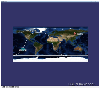
上图为利用osgEarth实现的二维场景,其中的卫星对象是时变对象,表示卫星位置的图标采用osgEarth的PlaceNode实现,卫星星下线和卫星覆盖均采用osg中的几何对象实现。上述两种方法的效率差别经测试,达肉眼可辩的程度。


 1243
1243


 被折叠的 条评论
为什么被折叠?
被折叠的 条评论
为什么被折叠?
 到【灌水乐园】发言


