


 本文介绍了如何在AVR固件上利用Z3定理进行USB驱动程序的开发和优化,翻译自一篇Medium文章。
固件avr usb驱动程序
As many of you may or may not be aware of, I have a serious obsession with embedded systems security. It wasn’t until about two years ago where I started my journey of incorporating my knowledge in reverse engineering software applications into pulling apart firmware from embedded devices. Additionally, I also started learning hardware security concepts such as side-channel attacks, fault-injections/glitch attacks, bit flipping, and more.
你们中很多人可能没有意识到,我对嵌入式系统的安全性非常痴迷。 直到大约两年前,我才开始将自己在逆向工程软件应用程序中的知识应用于从嵌入式设备中分离固件的旅程。 此外,我还开始学习硬件安全性概念,例如边通道攻击,故障注入/毛刺攻击,位翻转等。
Anyone who has began their careers in embedded security will tell you that the Arduino board is the best device to get started on. They have a pretty intricate IDE, and an abundant amount of HAL (Hardware Abstraction Layer) API calls to use. Needless to say, writing your first hello world application in the embedded systems industry is fairly rudimentary, which is just blinking an LED.
任何开始从事嵌入式安全性工作的人都会告诉您Arduino开发板是入门的最佳设备。 他们有一个非常复杂的IDE,以及大量要使用的HAL (硬件抽象层)API调用。 不用说,在嵌入式系统行业中编写您的第一个hello world应用程序是非常初级的,只是使LED闪烁。
The goal of this paper to show you how to use the Z3 formula (with python) to break weak password checkers that use linear inequalities or equalities such as satisfiability modulo theories.
本文的目的是向您展示如何使用Z3公式(使用python)打破使用线性不等式或等式(如可满足性模理论 )的弱密码检查器。
AVR架构 (AVR Architecture)
To give you some background on what Arduino uses as their main MCU (Microcontroller Unit), it will help to understand what AVR is. AVR is an 8-bit RISC architecture (Reduced Instruction Set Computing). AVR based microcontrollers became widely popular for being one of the first in the game to have on-chip flash storage. For the lab exercise, we will be using an Arduino Nano board with an ATmega328P MCU.
为了让您了解Arduino用作其主要MCU (微控制器单元)的背景,这将有助于您了解AVR是什么。 AVR是一种8位RISC架构(精简指令集计算)。 基于AVR的微控制器因成为游戏中首批具有片上闪存存储设备之一而广受欢迎。 对于实验练习,我们将使用带有ATmega328P MCU的Arduino Nano板。
What we have here is a 28-pin chip with an operating voltage that ranges from +1.8V to +5.5V. Only 23 of the 28 pins are programmable as GPIOs (General Purpose Input/Output). It does come with your standard set of communication interfaces such as Master/Slave SPI (Serial Peripheral Interface), USB, USART (Universal Synchronous/Asynchronous Receiver Transmitter), and Two-Wire peripheral protocols such as I2C (Inter-Integrated Circuit). We will discuss USB-to-USART more in depth later on as this will become important when flashing our chip with the target firmware and communicating with our chip by sending and receiving data.
我们这里拥有28针芯片,其工作电压范围为+ 1.8V至+ 5.5V。 28个引脚中只有23个引脚可作为GPIO (通用输入/输出)进行编程。 它确实带有一组标准的通信接口,例如主/从SPI(串行外设接口),USB,USART(通用同步/异步接收器发送器)和两线外设协议,例如I2C(内部集成电路)。 稍后我们将更深入地讨论USB-to-USART,因为这在使用目标固件刷新芯片并通过发送和接收数据与芯片通信时将变得很重要。
Let’s go over this diagram above;
让我们来看一下上面的图;
The data bus handles data in 8-bit chunks that travel inside the microcontroller, as the bus line is 8-bits wide.
数据总线以8位块的形式处理数据,这些数据在微控制器内部传输,因为总线线宽为8位。
General Purpose Registers are used for arithmetic operations such adding and subtracting numbers, setting jump pointers, and compare operations. From the previous article I wrote, we discussed registers for x86 architecture, and in this case of AVR we have R0…R31.
通用寄存器用于算术运算,例如加减数字,设置跳转指针以及比较运算。 在我写的上一篇文章中,我们讨论了x86体系结构的寄存器,在AVR的情况下,我们有R0…R31。
ALU stands for Arithmetic Logic Unit. This works in direct connection with the general purpose registers. Arithmetic operations between a GPR and an immediate operand can be executed within a single clock cycle. We can divide these operations into three categories: arithmetic, logical, and bit-wise functions.
ALU代表算术逻辑单元。 这与通用寄存器直接连接。 GPR和立即操作数之间的算术运算可以在单个时钟周期内执行。 我们可以将这些操作分为三类:算术,逻辑和按位函数。
Instruction Decoder is a combinational circuit whose purpose is to translate an instruction code into the address at micro-memory.
指令解码器是一种组合电路,其目的是将指令代码转换为微存储器中的地址。
Program Counter (PC) is 14 bits wide and addresses the program memory locations.
程序计数器 (PC)为14位宽,用于寻址程序存储位置。
As we can see from the picture above, there are three different types of memory being used here. 1) Flash Memory, which is programmable read-only memory (ROM), and firmware can only be changed using a programmer or bootloader. 2) SRAM, an area for volatile memory that holds data only when electrically powered. 3) Lastly, EEPROM (Electronically Erasable Programmable Read Only Memory), a semi permanent data storage that can only be accessed using special registers inside the AVR. It has the ability to control things like addresses to be written, data to be written, and flags used to read data.
从上图可以看出,这里使用了三种不同类型的内存。 1) 闪存 ,它是可编程的只读存储器(ROM),只能使用编程器或引导程序来更改固件。 2) SRAM ,一个易失性存储器区域,仅在通电时才保存数据。 3)最后是EEPROM (电可擦可编程只读存储器),这是一种半永久性数据存储,只能使用AVR中的特殊寄存器进行访问。 它具有控制诸如要写入的地址,要写入的数据以及用于读取数据的标志之类的功能。
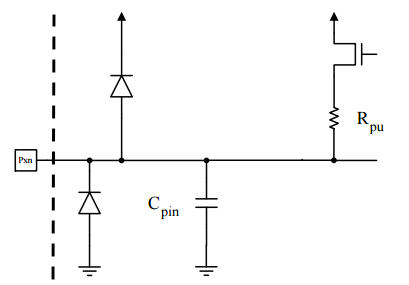
I/O Lines are used for controlling applications through the digital input and output pins. These pins can detect any voltage changes such as HIGH or LOW electromagnetic force digital output. All I/O pins are connected to diodes that trace to a VCC and GND line.
I / O线用于通过数字输入和输出引脚控制应用程序。 这些引脚可以检测任何电压变化,例如高或低电磁力数字输出。 所有I / O引脚都连接到二极管,该二极管跟踪VCC和GND线。
Now that we have a better understanding of AVR architecture, let’s briefly go over how we are going to communicate with our ATmega328P chip using USB-to-USART.
现在我们对AVR架构有了更好的了解,让我们简要介绍一下如何使用USB-to-USART与ATmega328P芯片进行通信。
美国ART (USART)
The USB-to-USART converter/bridge is a serial port to your computer and is responsible for sending serial data over two wires. There is no clock signal and no parleying between the two devices. To communicate accurately, both devices must be configured beforehand to use the same speed of communication, otherwise known as the baud rate. The baud rate is simply the rate at which information is transferred in a communication channel. In the serial port context, 9600 baud means that the serial port is capable of transferring at a maximum of 9600 bits per second. It can be calculated in two ways:
USB到USART的转换器/桥是计算机的串行端口,负责通过两根线发送串行数据。 两个设备之间没有时钟信号,也没有同位。 为了准确通信,必须预先将两个设备配置为使用相同的通信速度,否则称为波特率。 波特率只是在通信信道中传输信息的速率。 在串行端口上下文中, 9600 baud表示串行端口每秒最多可以传输9600位。 可以通过两种方式进行计算:
𝐷 = 𝐵⋅(𝑛/(𝑏+𝑛))
𝐵 = 𝐷⋅((𝑏+𝑛)/𝑛)
Where B is the defined as units of total bits per second, D is the application of data bits per second, and N is the bits that are conveyed per symbol, and the gross bit rate is R, inclusive of channel coding overhead, the symbol rate fs can be calculated as:
其中B定义为每秒总比特数的单位, D是每秒数据比特的应用数, N是每个符号传输的比特数,总比特率是R ,包括信道编码开销,该符号速率f s可以计算为:
f⋅(s) = R / NThe USART clock must operate at 16 times the desired baud rate. The clock is based around the operation of a crystal oscillator which, in the case of the ATmega328P USART, is set to a constant 3.6881 MHz.
USART 时钟必须以所需波特率的16倍运行。 该时钟基于晶体振荡器的操作,对于ATmega328P USART,该晶体振荡器设置为恒定的3.6881 MHz。
实验室作业 (Lab Assignment)
There are two files we are going to need for this exercise. Both of these files can be found at VirusTotal.
本练习将需要两个文件。 这两个文件都可以在VirusTotal中找到。
One is the bin file that is a dumped firmware image ->
7afa940272694061bde3d1eea7f4827a.一个是bin文件,它是一个转储的固件映像->
7afa940272694061bde3d1eea7f4827a。The second is the hex firmware file used to upload and be processed by our Arduino Nano board ->
4f055c15d3841872ba8156ffb968a8ab.第二个是用于上载Arduino Nano板->
4f055c15d3841872ba8156ffb968a8ab并进行处理的十六进制固件文件。
The next step to getting our board ready will be to upload the hex file we just downloaded by using avrdude. Connect the board to your computer via USB, and be sure to have installed avr-tools. The typical baud rate upload speed is going to be 57,600. We are going to run this at the command line to get the firmware on the board:
准备好开发板的下一步将是使用avrdude上传刚刚下载的hex文件。 通过USB将开发板连接至计算机,并确保已安装avr-tools 。 典型的波特率上载速度为57,600。 我们将在命令行上运行此命令以在板上获取固件:
➜ jumpy git:(master) avrdude -c arduino -p atmega328p -P /dev/cu.wchusbserial1410 -b57600 -u -V -U flash:w:jumpy.hexAt this point we need to figure out the what is the baud rate the USART is using to communicate all of its serial data. After running baudrate.py, you should get the result of 19,200. Now we can use the application screen to communicate with the board from our machine.
在这一点上,我们需要弄清楚USART用于传达其所有串行数据的波特率是多少。 运行baudrate.py之后 ,您应该得到19,200的结果。 现在,我们可以使用应用程序screen与机器上的主板进行通讯。
screen /dev/cu.wchusbserial1410 19200
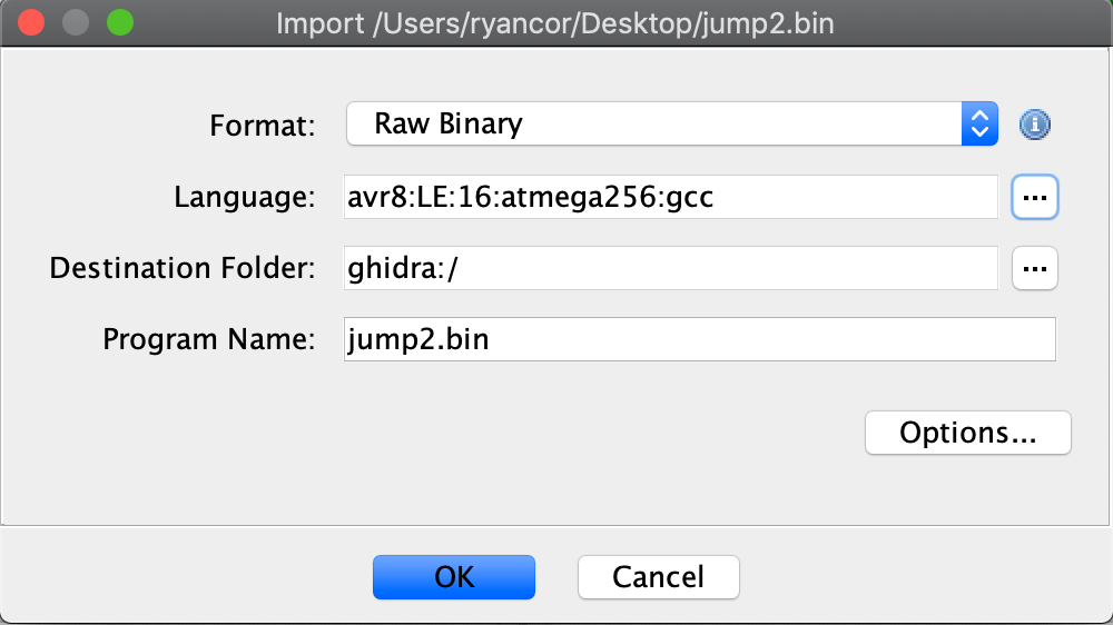
Looks like a pretty straightforward single-password check. Let’s move on over to the jumpy.bin file and start our reverse engineering process. We are going to use Ghidra for this project as I found it to be a lot cleaner when using the AVR disassembler. After we load the file into a project directory, specifying the language is a must; so in our case, AVR8 Little Endian 16-bit assembly was the best option.
看起来很简单的单密码检查。 让我们继续jumpy.bin到jumpy.bin文件并开始我们的逆向工程过程。 我们将在这个项目中使用Ghidra,因为我发现使用AVR反汇编程序时它要干净得多。 将文件加载到项目目录后,必须指定语言; 因此,在我们的案例中, AVR8 Little Endian 16位程序集是最佳选择。
Ghidra will automatically analyze all the code including the vector table at the start of the disassembly output. One thing to note: you will see a lot of opcodes that have not been analyzed in code section, and in that case we will highlight all those bytes and press D, this will automatically disassemble the opcodes and you can use the F key afterwards to create the newly examined code into a function.
Ghidra将在反汇编输出开始时自动分析所有代码,包括向量表。 需要注意的一件事:您将看到很多未在代码部分中进行分析的操作码,在这种情况下,我们将突出显示所有这些字节并按D ,这将自动反汇编操作码,之后您可以使用F键进行操作。将新检查的代码创建为函数。
After Ghidra has completed analyzing the binary file, the output can look a bit convoluted. The first set of subroutines are responsible for initializing the peripherals such as the USART/TX-RX, SPI, TIMER, PCINT, Interrupts, and Reset table.
在Ghidra完成对二进制文件的分析之后,输出看起来有些混乱。 第一组子例程负责初始化外设,例如USART / TX-RX,SPI,TIMER,PCINT,中断和复位表。

Side note: If you ever want to find the main() function in firmware code, trace to the base address to RESET -> code:000000 of the bootloader. It will always contain a simple jump (I.E. jmp lab_000045) to an address outside of the bootloader that will directly lead to a start routine that holds main() after performing a lot of operations to setup the environment.
注意:如果要在固件代码中找到main()函数,请跟踪至引导加载程序的RESET -> code:000000的基地址。 它总是包含一个简单的跳转(IE jmp lab_000045 )到引导加载程序外部的地址,该地址将直接执行一个启动例程,该例程在执行许多设置环境的操作后将保留main() 。

We will most likely have better luck doing dynamic analysis, which won’t be easy, but will definitely give a lot more satisfying results. The strings table doesn’t show much and there are no XREF’s to any of the offsets in code segment.
我们很可能会幸运地进行动态分析,这并非易事,但肯定会带来更多令人满意的结果。 字符串表显示不多,并且代码段中的任何偏移量都没有XREF。

仿真器 (Emulator)
The goal right now is to emulate the code and figure out where the firmware is asking for input from the user in the USART. We have to find an offset in the beginning to set a breakpoint at so we can commence step-tracing. The first offset (0xaa) I noticed that shows logical code is at function 0x003cc.
现在的目标是模拟代码并找出固件在哪里要求USART中的用户输入。 我们必须在开始处找到一个偏移量以在此处设置断点,以便我们可以开始逐步跟踪。 我注意到显示逻辑代码的第一个偏移量( 0xaa )位于函数0x003cc 。
FUN_code_0003cc:0003d2(c)
     code:0000aa cf 93           push       Ylo
     code:0000ab df 93           push       Yhi
     code:0000ac cd b7           in         Ylo,SPL
     code:0000ad de b7           in         Yhi,SPH
     code:0000ae 60 97           sbiw       Y,0x10
Before we start up our debugger, there are three tools you are going to need to download:
在启动调试器之前,需要下载以下三个工具:
SimAvr => https://github.com/buserror/simavr
SimAvr => https://github.com/buserror/simavr
Picocom => https://github.com/npat-efault/picocom
Picocom => https://github.com/npat-efault/picocom
Avr-Gdb => https://github.com/igormiktor/build-avr-gcc
Avr-Gdb => https://github.com/igormiktor/build-avr-gcc
Open three terminal windows and let’s start with the first one. Run this simavr-simduino command:
打开三个终端窗口,让我们从第一个窗口开始。 运行以下simavr-simduino命令:
$ board_simduino/obj-x86_64-linux-gnu/simduino.elf -d jumpy.hex
atmega328p booloader 0x00000: 3402 bytes
avr_special_init
avr_gdb_init listening on port 1234
uart_pty_init bridge on port *** /dev/pts/1 ***
uart_pty_connect: /tmp/simavr-uart0 now points to /dev/pts/1
note: export SIMAVR_UART_XTERM=1 and install picocom to get a terminal
Next is picocom, which will be used as a bridge for the USART communication. In the next terminal window, run this command:
接下来是picocom,它将用作USART通信的桥梁。 在下一个终端窗口中,运行以下命令:
$ picocom /tmp/simavr-uart0
picocom v2.2port is        : /tmp/simavr-uart0
flowcontrol    : none
baudrate is    : 9600
parity is      : none
databits are   : 8
stopbits are   : 1
escape is      : C-a
local echo is  : no
noinit is      : no
noreset is     : no
nolock is      : no
send_cmd is    : sz -vv
receive_cmd is : rz -vv -E
imap is        :
omap is        :
emap is        : crcrlf,delbs,Type [C-a] [C-h] to see available commandsTerminal ready
This setup will now get us ready to connect to a GDB server. We can now run avr-gdb in the third terminal.
现在,此设置将使我们准备连接到GDB服务器。 现在,我们可以在第三个终端中运行avr-gdb 。
$ avr-gdb ./jumpy.bin
(gdb) target remote localhost:1234
Remote debugging using localhost:1234
0x00000000 in ?? ()
(gdb) break *($pc + 0x000000aa)
Breakpoint 1 at 0xaa
(gdb) c
Continuing.Breakpoint 1 hit, 0x000000aa in ?? ()
Looking at picocom, it doesn’t look like we have hit any sort of text output yet, so we haven’t yet reached the point where the code is sending data through the USART terminal. Using the gdb command stepi 20 is a good trial and error technique to see how much we should step in the beginning before the first letter is output to the pico terminal. Interestingly, we hit the breakpoint again at 0xaa, and if we switch back to picocom, we can see the letters In being printed on the screen. This function looks like it is responsible for sending data over TX. Tracing back into Ghidra, it looks like we are hitting this peripheral component:
看picocom,看起来我们还没有击中任何形式的文本输出,因此我们还没有达到代码通过USART终端发送数据的地步。 使用gdb命令stepi 20是一种很好的反复试验技术,它可以了解在第一个字母输出到pico终端之前,我们应该从头开始执行多少操作。 有趣的是,我们再次在0xaa处达到了断点,如果切换回picocom,我们可以In屏幕上看到In字母。 该功能看起来像负责通过TX发送数据。 追溯到Ghidra,看起来我们正在使用以下外围组件:
undefined USART2_RX()
             undefined         Wlo:1          <RETURN>
             undefined1[255]   Stack[-0x100   buf
                             USART2_RX                                       XREF[1]:     Entry Point(*)
     code:000066 1f 92           push       R1
     code:000067 cd b7           in         Ylo,SPL
After stepping a few more times, we come to a point where we can find directly what is printing to the picocom terminal.
再经过几次后,我们可以直接找到要打印到picocom终端的内容。
(gdb) x/10i $pc
=> 0xd0: st Z, r18
   0xd2: pop r0
   0xd4: pop r29
   0xd6: pop r28
   0xd8: ret
   0xda: push r28
   0xdc: push r29
   0xde: in r28, 0x3d ; 61
   0xe0: in r29, 0x3e ; 62
   0xe2: ldi r24, 0xC5 ; 197
(gdb) i r $r18
r18            0x75 11
Hex 0x75 is ‘u’ which makes sense if it’s printing the string Input. Whats happening here in the code is the register r18 holds the next byte to store into Z using the st instruction. Looking at the Atmel instruction manual, we can see exactly what this operation is doing. It indirectly stores from the register to the data space using index X or Z. If you look how Ghidra decompiles this logic, it will look like this:
十六进制0x75是'u' ,这在打印字符串Input是有意义的。 代码中发生的是寄存器r18使用st指令将下一个字节存储到Z 。 查看Atmel说明手册 ,我们可以确切地看到此操作在做什么。 它使用索引X或Z从寄存器间接存储到数据空间。 如果您查看Ghidra如何反编译此逻辑,它将看起来像这样:
undefined2 USART3_TX(byte param_1)
{
  ...
  R18 = *(undefined *)(Y + 1);
  write_volatile_1(UDR0,R18);
}
Y is the array index that holds our string table, and the st instruction is seen as a volatile write to the DR0 (Data/Debug Register). Now we can make note that in GDB offset 0xaa (0x66 in Ghidra) is part of the USART-RX, and offset 0xbe (0x70 in Ghidra) is responsible for the USART-TX. Side Note: Some register pairs can be used for 16-bit operations. These can only be used with the register pairs R26:R27 (X), R28:R29 (Y), and R30:R31 (Z). I’m clarifying this because there was some confusion around debugging information in memory; so if we wanted to dump contents of Y using GDB, the command would be crafted like this -> x/10x $R28.
Y是保存我们的字符串表的数组索引,并且st指令被视为对DR0 (数据/调试寄存器)的易失性写入。 现在我们可以注意到,在GDB中,偏移量0xaa (在Ghidra中为0x66 )是USART-RX的一部分,偏移量0xbe (在Ghidra中为0x70 )是USART-TX的责任。 旁注:某些寄存器对可用于16位操作。 这些只能与寄存器对R26:R27 (X) , R28:R29 (Y)和R30:R31 (Z) 。 我之所以澄清,是因为调试内存中的信息有些混乱; 因此,如果我们想使用GDB转储Y内容,则该命令的格式应如下所示-> x/10x $R28 。
Now that the TX/RX interrupts are located, we need to be able to find where our input is actually processed. After stepping through a bunch of the code, it looks like we may have found in Ghidra where our input gets processed:
现在已经找到了TX / RX中断,我们需要能够找到输入的实际处理位置。 在完成了一系列代码之后,看起来我们可能在Ghidra中找到了处理输入的地方:
code:000171 8a 30           cpi        r24,0xa
code:000172 99 f0           brbs       LAB_code_000186,Zflg
code:000173 8b 81           ldd        r24,Y+0x3
code:000174 8d 30           cpi        r24,0xd
CPI is responsible for comparing an immediate value. What sparked my interest when looking at this was the value 0xd and 0xa which is \r and \n in ascii. My theory is, if we set a breakpoint at the start of this function which is offset 0x2ac (0x167 in Ghidra), the picocom terminal will prompt us for an input and allow us to enter a string. After hitting enter, we should hit the breakpoint.
CPI负责比较即时值。 引起我兴趣的是值0xd和0xa (ascii中的\r和\n )。 我的理论是,如果我们设定该功能,抵消开始断点0x2ac ( 0x167在Ghidra),该picocom终端将提示我们输入,并允许我们输入一个字符串。 点击回车后,我们应该点击断点。
/* GDB Window */
(gdb) break *($pc + 0x000002ac)
Breakpoint 1 at 0x2ac
(gdb) c
Continuing.
Note: automatically using hardware breakpoints for read-only addresses.Breakpoint 1, 0x000002ac in ?? ()
(gdb)/* Pico Terminal */
Terminal ready
Input:
It looks like the breakpoint was hit without giving us the opportunity to input a string. Let’s continue browsing the stack:
似乎断点被击中而没有给我们机会输入字符串。 让我们继续浏览堆栈:
process_input
     code:000167 1f 92           push       R1
     code:000168 cd b7           in         Ylo,SPL
     code:000169 de b7           in         Yhi,SPH
     code:00016a 1a 82           std        Y+0x2,R1
     code:00016b 19 82           std        Y+0x1,R1
     code:00016c 15 c0           rjmp       LAB_code_000182
                             LAB_code_00016d
     code:00016d 0e 94 54 01     call       FUN_code_000154
From where we set our breakpoint, it looks like there is a function call at offset 0x154. Decompiling this function, we get the output:
从设置断点的位置看,偏移量0x154处似乎有一个函数调用。 反编译此函数,我们得到输出:
uint FUN_code_000154(void)
{
  byte bVar1;

  do {
    W._0_1_ = uart_read_char();
  } while ((char)W == '\0');
  bVar1 = read_volatile_1(UDR0);
  W = (uint)bVar1;
  Z = 0xc6;
  return W;
}
Subroutine looks simple enough to understand… it sets up the W register to interpret bits from the USART status and control register, if successful, it then takes a byte at a time and reads from the USART data register. Until a null terminating character is found, W will hold the entire value. Knowing this, we have to set a breakpoint after this function call, which will be at offset 0x2bc (0x15b in Ghidra). Let’s try this again, set a breakpoint at the new offset, and see if it works this time.
子例程看起来很简单,易于理解……它设置了W寄存器以解释USART状态和控制寄存器中的位,如果成功,则它一次要占用一个字节并从USART数据寄存器中读取。 在找到空终止符之前, W将保留整个值。 认识到这一点,我们有这个函数调用,这将是在偏移后设置一个断点0x2bc ( 0x15b在Ghidra)。 让我们再试一次,在新的偏移量处设置一个断点,看看这次是否有效。
/* GDB Window */
(gdb) break *($pc + 0x000002bc)
Breakpoint 1 at 0x2bc
(gdb) c
Continuing.
Note: automatically using hardware breakpoints for read-only addresses./* Pico Terminal */
Terminal ready
Input:helloworld/* Breakpoint hit in GDB Window after hitting enter */
Breakpoint 1, 0x000002bc in ?? ()
(gdb)
Perfect! From what we saw before $r24 holds each byte and compares it to an \n or an \r. To confirm we can see if the register holds our first byte ‘h’, (gdb) i r $r24 == 0x68 <=> 104; and it does! At this offset, we will be hitting this breakpoint X amount of times, X being equal to the size of our string + 1. Once the code processes the null terminating string, the function exits. Our input string will be held at this address below.
完善! 从我们之前看到的$r24保存每个字节并将其与\n或\r 。 为了确认,我们可以查看寄存器是否保存了我们的第一个字节'h' , (gdb) ir $r24 == 0x68 <=> 104 ; 确实如此! 在这个偏移量处,我们将达到该断点X倍的次数, X等于string + 1的大小string + 1 。 代码处理完空终止字符串后,函数将退出。 我们的输入字符串将保存在下面的此地址。
(gdb) x/1s 0x80013e
0x80013e: "helloworld"
Time to step out of this function and see where this routine is being cross-referenced. Once we reach the return instruction, the $pc will be redirected to a module at:
是时候退出此功能,看看该例程在哪里被交叉引用。 一旦我们到达return指令, $pc将被重定向到以下模块:
undefined FUN_code_000192()
             undefined         Wlo:1          <RETURN>
             undefined1[256]   Stack[-0x100]   buffer
                             FUN_code_000192
     code:000192 cf 93           push       Ylo
     code:000193 df 93           push       Yhi
     code:000194 1f 92           push       R1
     code:000195 cd b7           in         Ylo,SPL
     code:000196 de b7           in         Yhi,SPH
     code:000197 19 82           std        Y+0x1,R1
This could be the winning ticket for what happens next with our string. Just to keep track, we are at offset 0x302 (0x192 in Ghidra). I started to step through this function one instruction at a time, and it looks like it wasn’t actually comparing anything of interest once this function returned. Something interesting started to show once we got a bit further down the code base:
这可能是我们字符串接下来发生的事情的中奖彩票。 只是为了保持跟踪,我们在偏移0x302 ( 0x192在Ghidra)。 我开始每次只执行一条功能指令,而一旦该功能返回,似乎并没有真正比较任何感兴趣的东西。 一旦我们进一步深入代码库,就会开始显示出一些有趣的东西:
code:0001c7 82 0f           add        Wlo,R18
code:0001c8 93 1f           adc        Whi,R19
code:0001c9 83 3d           cpi        Wlo,0xd3
code:0001ca 91 05           cpc        Whi,R1
code:0001cb 51 f4           brbc       LAB_code_0001d6,Zflg
Looks like two registers are being added then compared to a value of 0xd3. Let’s set a breakpoint here in gdb at offset 0x36c, and see what values of our input are possibly being added together.
看起来正在添加两个寄存器,然后将其与0xd3的值进行0xd3 。 让我们在gdb的偏移量0x36c处设置一个断点,看看可能将我们的输入值加在一起。
/* GDB Window */
(gdb) break *($pc + 0x0000036c)
Breakpoint 1 at 0x36c
(gdb) c
Continuing.
Note: automatically using hardware breakpoints for read-only addresses./* Pico Terminal */
Terminal ready
Input:helloworld923/* Breakpoint hit in GDB Window after hitting enter */
Breakpoint 1, 0x0000036c in ?? ()
(gdb) x/3i $pc
=> 0x36c: add r24, r18
   0x36e: adc r25, r19
   0x370: cpi r24, 0xD3 ; 211
(gdb) i r $r24
r24            0x6c 108
(gdb) i r $r18
r18            0x72 114
We can see index 7 (‘r’) and index 8 (‘l’) added; this will give us the hexadecimal value of 0xde. Now that we know this routine begins at 0x1bb in Ghidra, we can rename this function compare_index_7_8(). As we move further down the code base, we start to see a lot of similar code. Side note: start labeling all comparative functions to keep track of what indices your input string are being are being compared to.
我们可以看到添加了索引7( 'r' )和索引8( 'l' )。 这将给我们十六进制值0xde 。 现在我们知道该例程从0x1bb中的0x1bb开始,我们可以将该函数重命名为compare_index_7_8() 。 随着代码基础的进一步深入,我们开始看到很多类似的代码。 旁注:开始标记所有比较函数,以跟踪输入字符串要与哪些索引进行比较。
/* Comparing Index 9 and 10 */
code:00021f 82 0f           add        Wlo,R18
code:000220 93 1f           adc        Whi,R19
code:000221 8f 38           cpi        Wlo,0x8f/* Comparing Index 11 and 12 */
code:0002fa 82 0f           add        Wlo,R18
code:0002fb 93 1f           adc        Whi,R19
code:0002fc 80 3a           cpi        Wlo,0xa0/* Comparing Index 6 and 7 */
code:0002b5 52 9f           mul        R21,R18
code:0002b6 90 0d           add        Whi,R0
code:0002b7 11 24           eor        R1,R1
code:0002b8 8c 30           cpi        Wlo,0xc
code:0002b9 9b 42           sbci       Whi,0x2b
code:0002ba 51 f4           brbc       LAB_code_0002c5,Zflg
Over at address 0x2b5, there is an operation that looks a bit different from the other comparisons. Index 6 and 7 of our input string gets their ordinals multiplied by each other, then gets compared to a lower WORD byte value of the result to 0xc and higher byte value of that WORD to 0x2b. In our example, we can take the two indices of ‘o’ and ‘r’ from helloworld923 and multiply the two integers to obtain the value 0x316e; the lower byte of this WORD (LOWORD) in this equation is 0x6e and the higher byte (HIWORD) value is 0x31. This is how the comparison will look like in pseudo-code:
在地址0x2b5 ,有一个操作看起来与其他比较有所不同。 输入字符串的索引6和7的序数彼此相乘,然后与结果的较低WORD字节值比较为0xc和该WORD的较高字节值比较为0x2b 。 在我们的示例中,我们可以从helloworld923中获取'o'和'r'的两个索引,并将两个整数相乘以获得值0x316e ; 在0x6e式中,此WORD的低字节( LOWORD )为0x6e ,高字节( HIWORD )值为0x31 。 这是伪代码中的比较结果:
if (ord(‘o’) * ord(‘r’)) >> 8 == 0x2b
The sbci instruction subtracts with the carry immediate command, and our final value that index 6 and 7 will need to equal is 0x2b0c. Static analysis will really take care of the rest from here on out because we know what specific mnemonics to keep an eye out for. We can build up our constraints table and use the Z3 theorem to solve the rest. The size of our string has to be 13 characters as seen in this snippet of decompiled code:
sbci指令用进位立即命令减去,索引6和7需要相等的最终值为0x2b0c 。 从现在开始,静态分析将真正解决其余问题,因为我们知道需要注意哪些特定的助记符。 我们可以建立约束表,并使用Z3定理求解其余部分。 如以下反编译代码段所示,字符串的大小必须为13个字符:
if (var_37 == 0xd) {
W = (char *)(CONCAT11(DAT_mem_013f,DAT_mem_013e) | 1);
input_string = (char)W;
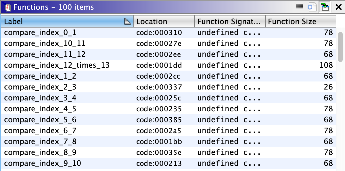
}Inside your Ghidra Functions tab, you should have labeled all 13 subroutines responsible for comparing each byte of your input.
在Ghidra功能选项卡中,您应该标记了负责比较输入的每个字节的所有13个子例程。
Z3定理解决方案 (Z3 Theorem Solution)
To put it simply, Z3 Prover was created for Satisfiability Modulo Theories (SMT) problems. These are decision problems for logical formulas with combinations that include arithmetics, bit-vectors, arrays, and unresolved functions. Z3 is an effective SMT solver with specialized algorithms to solve background theories as mentioned above. You can download the python library here.
简而言之,Z3 Prover是为满足满意度模理论 ( SMT )问题而创建的。 这些是逻辑公式的决策问题,这些逻辑公式的组合包括算术,位向量,数组和未解析的函数。 Z3是一种有效的SMT求解器,具有专用算法来解决上述背景理论。 您可以在此处下载python库。
At this point we can formulate the conditionals on how this firmware code checks for the right password and what constraints we can enter into our bit-vector that can be used as shorthands for sub-terms.
在这一点上,我们可以制定条件来确定此固件代码如何检查正确的密码,以及可以输入到位向量中的哪些约束条件,这些条件可以用作子术语的缩写。
if string[7] + string[8] == 0xd3 ⇒
  if string[8] * string[9] == 0x15c0 ⇒
     if string[0] * string[1] == 0x13b7 ⇒
        if string[2] * string[3] == 0x1782 ⇒
           if string[3] + string[4] == 0x92 ⇒
              if string[6] * string[7] == 0x2b0c ⇒
                 if string[5] + string[6] == 0xa5 ⇒
                    if string[9] + string[10] == 0x8f ⇒
                       if string[1] + string[2] == 0xa7 ⇒
                          if string[10] * string[11] == 0x2873 ⇒
                             if string[12] * 13 == 0x297 ⇒
                                 ...
                                 -> decrypt_flag()
Side Note: The flag string gets loaded at Ghidra’s offset 0x55. It will use the instruction lpm to load a data byte from the FLASH program memory into the register file. The Z-register in the register file is then used to access the program memory and place the data in register R0. A final check function will be called at offset 0x3a7 to confirm how many times the variable isCompared was set to be true | 1. If equal to (1<<14)–1, then the code will proceed to print the flag.
注意:标志字符串在Ghidra的偏移量0x55处加载。 它将使用指令lpm将数据字节从闪存程序存储器加载到寄存器文件中。 然后,使用寄存器文件中的Z寄存器访问程序存储器并将数据放入寄存器R0 。 将在偏移量0x3a7处调用最终检查函数,以确认将变量isCompared设置为true | 1 true | 1 。 如果等于(1<<14)–1 ,则代码将继续打印该标志。
LAB_code_000051:
code:000051    lpm        R0,Z=>s__FLAG:_code_0006e4+ = "\r\nFLAG:"
...
code:0003af 8f 3f           cpi        Wlo,0xff
code:0003b0 9f 43           lsl        Whi,0x0e
code:0003b1 99 f4           brbc       LAB_0003c5,Zflg ; not equal
code:0003b2 80 e0           ldi        Wlo,0x0
code:0003b3 91 e0           ldi        Whi,0x1
code:0003b4 0e 94 aa 00     call       usart_print
...
LAB_0003c5:  // if landed here, you'll get the "wrong password" msg
code:0003c5 8b e0           ldi        Wlo,0xb
code:0003c6 91 e0           ldi        Whi,0x1
code:0003c7 0e 94 aa 00     call       usart_print
After all values are added to your constraints, you can use Z3’s check() function to examine whether the assertions in the given solver plus the optional assumptions are consistent or not. If the assertion returns true, the next step would be to return a model() for the last check(). This function raises an exception if a model is not available (e.g., last check() returned unsat; your assignment doesn’t satisfy the quantified axiom). A simple test to see how the library works would be to use a three unknown linear equation from our challenge like x+y = 0xd3 && y*z = 0x15c0:
将所有值添加到约束后,您可以使用Z3的check()函数检查给定求解器中的断言与可选假设是否一致。 如果断言返回true,则下一步将是为最后一个check()返回一个model() check() 。 如果模型不可用(例如,最后的check()返回unsat ;您的分配不满足量化的公理),则此函数引发异常。 观察库如何工作的简单测试是使用我们挑战中的三个未知线性方程,例如x+y = 0xd3 && y*z = 0x15c0 :
>>> from z3 import *
>>> x,y,z = Int('x'), Int('y'), Int('z')# Test with no solutions
>>> s = SimpleSolver()
>>> s.add(2**x == 4)
>>> s.check()
unknown
>>> s.add(2**x == 16)
>>> s.check()
unsat# Reset general purpose solver with limited amount of preprocessing
>>> s = SimpleSolver()
>>> s.add(x + y == 0xd3)
>>> s.add(y * z == 0x15c0)
>>> s.check()
sat
>>> s.model()
[z = 348, y = 16, x = 195]
We can apply the same logic to our unknowns mentioned above. But as you can see, if Z3 is unable to satisfy the requirements needed to model the solution, it will return an unknown and everything added after will be considered unsatisfiable.
我们可以对上述未知数应用相同的逻辑。 但是,正如您所看到的,如果Z3无法满足对解决方案进行建模所需的要求,它将返回一个未知数,并且之后添加的所有内容都将被视为无法满足。
After running our solver, we finally get the password that is needed to decrypt the flag:
运行完求解器后 ,我们最终获得解密标志所需的密码:
ryancor@ryancor-VirtualBox:~$ python solve.py
Found Password: g1v3_1t_t0_m3
The next step would be to program a module that takes this password, automatically sends it to the ATMega’s USART serial port, and retrieves the flag. The source code for this script can be found here. In order to do this, make sure to have your board plugged into the USB port and connected to your linux VM USB ports. To ensure your VM recognizes this device, check your kernel message logs right after its plugged in and you should see that the usb-core registered a new interface driver called ch341:
下一步将是对使用此密码的模块进行编程,将其自动发送到ATMega的USART串行端口,并检索标志。 该脚本的源代码可以在这里找到。 为此,请确保将主板插入USB端口并连接到linux VM USB端口。 为了确保您的VM能够识别此设备,请在插入设备后立即检查内核消息日志,您应该看到usb-core注册了一个名为ch341的新接口驱动程序:
ryancor@ryancor-VirtualBox:~$ dmesg
[  231.342712] VBOXGUEST_IOCTL_HGCM_CALL: 64 Failed. rc=-54
[ 1054.110148] usb 2-2: new full-speed USB device number 3 using
[ 1054.447882] usb 2-2: New USB device found, idVendor=1a86,
[ 1054.447885] usb 2-2: New USB device strings: Mfr=0, Product=2,
[ 1054.447886] usb 2-2: Product: USB2.0-Serial
[ 1054.477153] usbcore: registered new interface driver
[ 1054.477430] usbserial: USB Serial support registered for generic
[ 1054.479961] usbcore: registered new interface driver ch341
[ 1054.480080] usbserial: USB Serial support registered for ch341-
[ 1054.480141] ch341 2-2:1.0: ch341-uart converter detected
[ 1054.502669] usb 2-2: ch341-uart converter now attached to ttyUSB0
In my case, the port I’m going to connect to in my python script will be located at /dev/ttyUSB0. After running our script, we get a successful decrypted flag from the microcontroller.
就我而言,我要在python脚本中连接的端口位于/dev/ttyUSB0 。 运行脚本后,我们从微控制器获得了成功的解密标志。
ryancor@ryancor-VirtualBox:~$ python solve.py
[+] Found Password: g1v3_1t_t0_m3
[!] Sending input to driver...FLAG:D0_you_3ven_ROP?
Thank you for following along! I hope you enjoyed it as much as I did. If you have any questions on this article or where to find the challenge, please DM me at my Instagram: @hackersclub or Twitter: @ringoware
感谢您的关注! 希望您能像我一样喜欢它。 如果您对本文有任何疑问或在哪里可以找到挑战,请在我的Instagram:@hackersclub或Twitter:@ringoware上与我联系。
Happy Hunting :)
快乐狩猎:)
P.S. If you missed the link to my Z3 solver program above, you can find the source code here.
PS如果您错过了上面我的Z3解算器程序的链接,则可以在此处找到源代码。
翻译自: https://medium.com/@ryancor/using-z3-theorem-on-avr-firmware-c6d2f45ac9c2
固件avr usb驱动程序


 423
423

 被折叠的 条评论
为什么被折叠?
被折叠的 条评论
为什么被折叠?
 到【灌水乐园】发言


