


 C4模型是一种用于描述和沟通软件架构的方法,它通过创建上下文、容器、组件和代码图来展示不同级别的细节。该模型帮助团队有效地向不同受众传达软件设计,无论是前期设计还是后期文档化。文章介绍了C4模型的各个层次,包括系统上下文、容器(应用和数据存储)、组件以及代码实现,并提到了相关的工具和技术。
Maps of your code
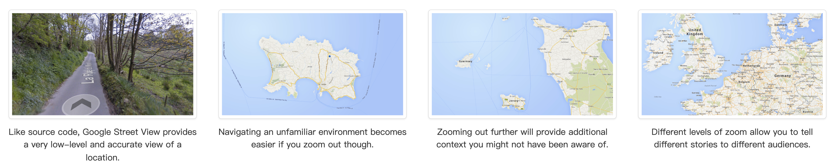
The C4 model was created as a way to help software development teams describe and communicate software architecture, both during up-front design sessions and when retrospectively documenting an existing codebase. It’s a way to create maps of your code, at various levels of detail, in the same way you would use something like Google Maps to zoom in and out of an area you are interested in.
Although primarily aimed at software architects and developers, the C4 model provides a way for software development teams to efficiently and effectively communicate their software architecture, at different levels of detail, telling different stories to different types of audience, when doing up front design or retrospectively documenting an existing codebase.
C4 Model
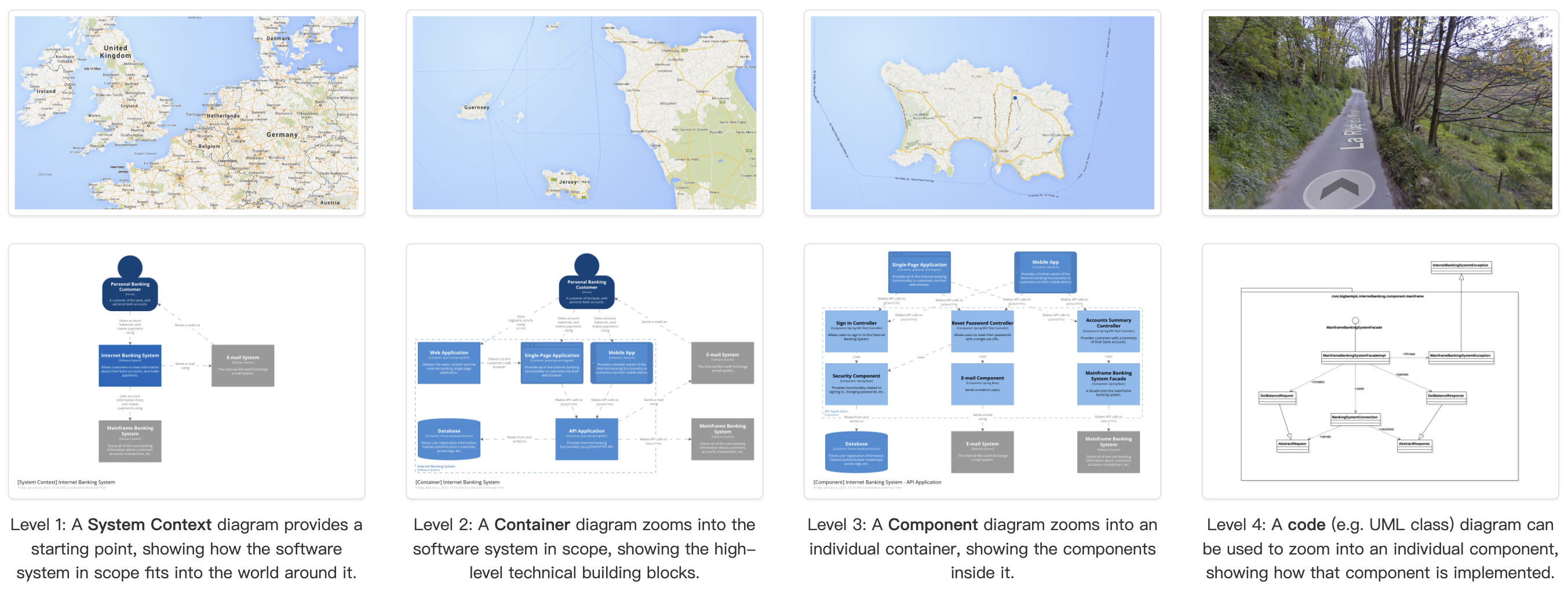
Visualising this hierarchy of abstractions is then done by creating a collection of Context, Container, Component and Code (e.g. UML class) diagrams. This is where the C4 model gets its name from.
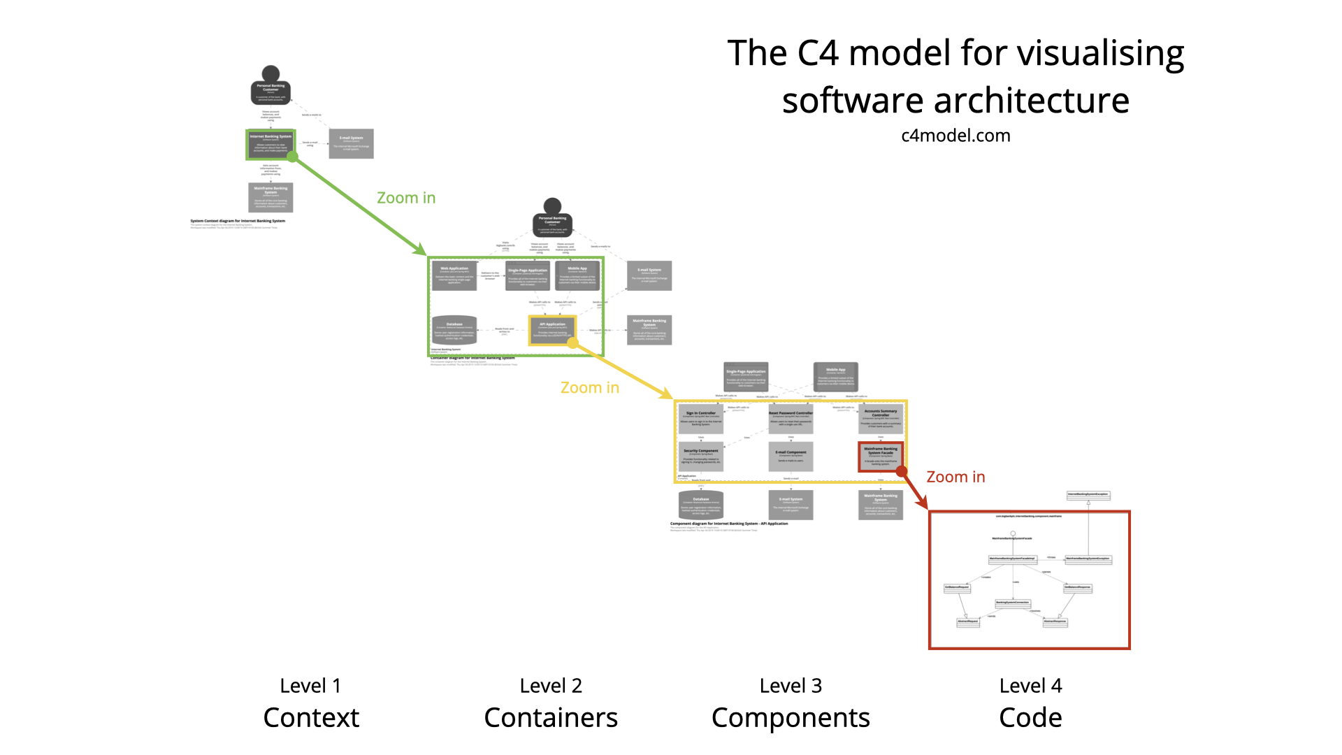
A software system is made up of one or more containers (applications and data stores), each of which contains one or more components, which in turn are implemented by one or more code elements (classes, interfaces, objects, functions, etc).
Abstractions
Person
A person represents one of the human users of your software system (e.g. actors, roles, personas, etc).
Software System
A software system is the highest level of abstraction and describes something that delivers value to its users, whether they are human or not. This includes the software system you are modelling, and the other software systems upon which your software system depends (or vice versa). In many cases, a software system is “owned by” a single software development team.
Container (applications and data stores)
Not Docker! In the C4 model, a container represents an application or a data store. A container is something that needs to be running in order for the overall software system to work. In real terms, a container is something like:
- Server-side web application: A Java EE web application running on Apache Tomcat, an ASP.NET MVC application running on Microsoft IIS, a Ruby on Rails application running on WEBrick, a Node.js application, etc.
- Client-side web application: A JavaScript application running in a web browser using Angular, Backbone.JS, jQuery, etc.
- Client-side desktop application: A Windows desktop application written using WPF, an OS X desktop application written using Objective-C, a cross-platform desktop application written using JavaFX, etc.
- Mobile app: An Apple iOS app, an Android app, a Microsoft Windows Phone app, etc.
- Server-side console application: A standalone (e.g. “public static void main”) application, a batch process, etc.
- Serverless function: A single serverless function (e.g. Amazon Lambda, Azure Function, etc).
- Database: A schema or database in a relational database management system, document store, graph database, etc such as MySQL, Microsoft SQL Server, Oracle Database, MongoDB, Riak, Cassandra, Neo4j, etc.
- Blob or content store: A blob store (e.g. Amazon S3, Microsoft Azure Blob Storage, etc) or content delivery network (e.g. Akamai, Amazon CloudFront, etc).
- File system: A full local file system or a portion of a larger networked file system (e.g. SAN, NAS, etc).
- Shell script: A single shell script written in Bash, etc.
- etc
A container is essentially a context or boundary inside which some code is executed or some data is stored. And each container is a separately deployable/runnable thing or runtime environment, typically (but not always) running in its own process space. Because of this, communication between containers typically takes the form of an inter-process communication.
Component
The word “component” is a hugely overloaded term in the software development industry, but in this context a component is a grouping of related functionality encapsulated behind a well-defined interface. If you’re using a language like Java or C#, the simplest way to think of a component is that it’s a collection of implementation classes behind an interface. Aspects such as how those components are packaged (e.g. one component vs many components per JAR file, DLL, shared library, etc) is a separate and orthogonal concern.
An important point to note here is that all components inside a container typically execute in the same process space. In the C4 model, components are not separately deployable units.
Level 1: System Context diagram
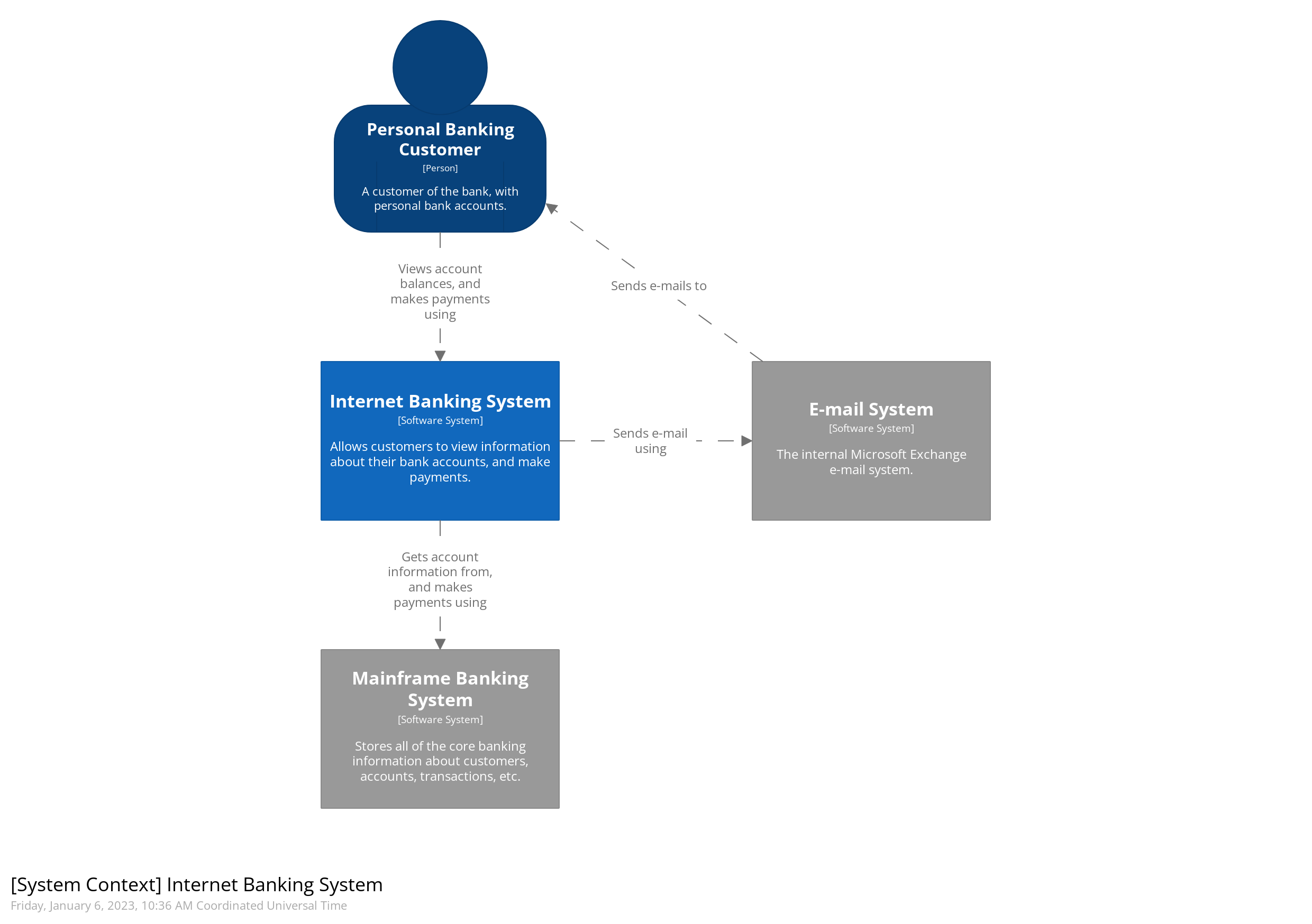

A System Context diagram is a good starting point for diagramming and documenting a software system, allowing you to step back and see the big picture. Draw a diagram showing your system as a box in the centre, surrounded by its users and the other systems that it interacts with.
Detail isn’t important here as this is your zoomed out view showing a big picture of the system landscape. The focus should be on people (actors, roles, personas, etc) and software systems rather than technologies, protocols and other low-level details. It’s the sort of diagram that you could show to non-technical people.
Level 2: Container diagram
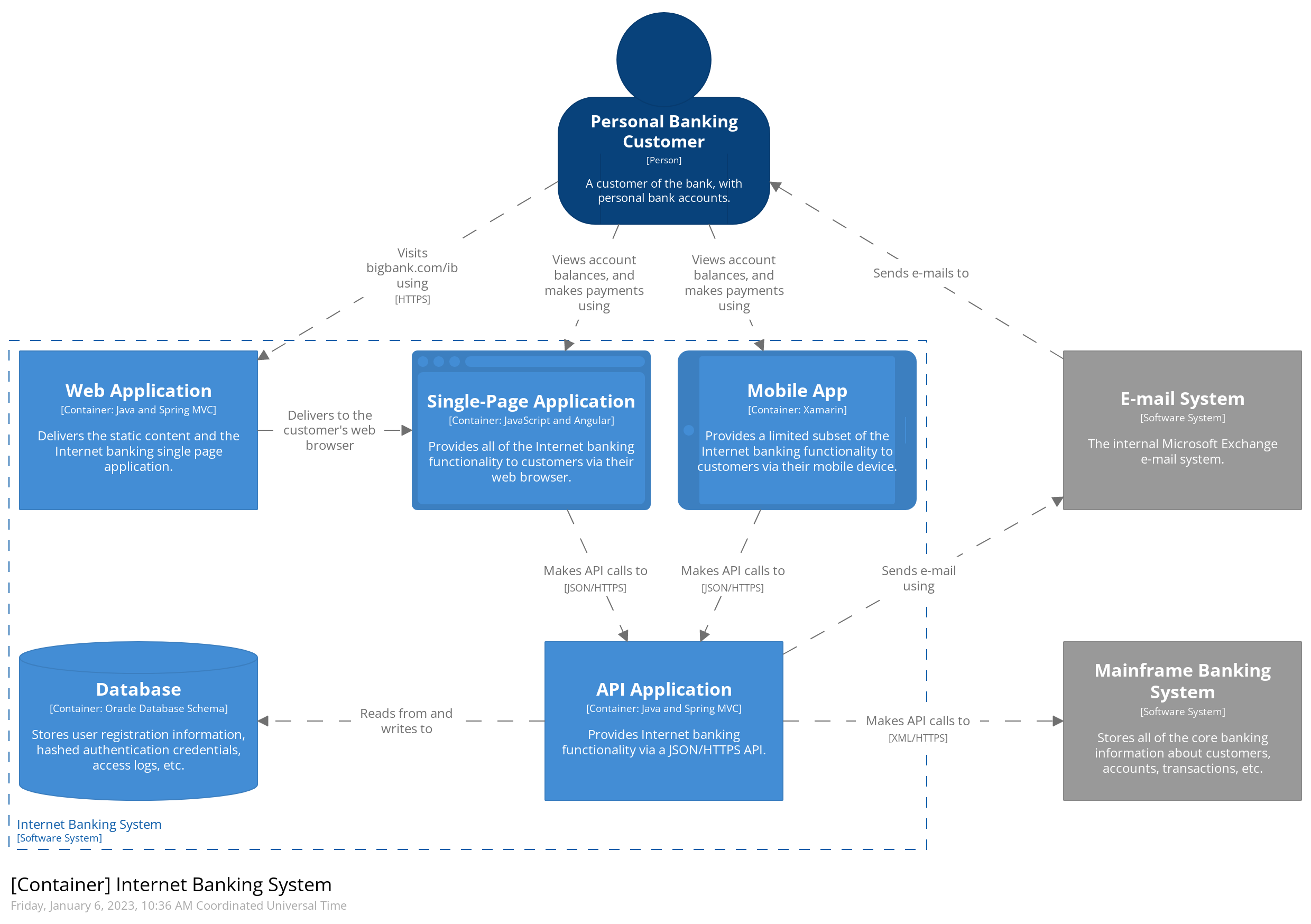

Once you understand how your system fits in to the overall IT environment, a really useful next step is to zoom-in to the system boundary with a Container diagram. A “container” is something like a server-side web application, single-page application, desktop application, mobile app, database schema, file system, etc. Essentially, a container is a separately runnable/deployable unit (e.g. a separate process space) that executes code or stores data.
The Container diagram shows the high-level shape of the software architecture and how responsibilities are distributed across it. It also shows the major technology choices and how the containers communicate with one another. It’s a simple, high-level technology focussed diagram that is useful for software developers and support/operations staff alike.
Level 3: Component diagram
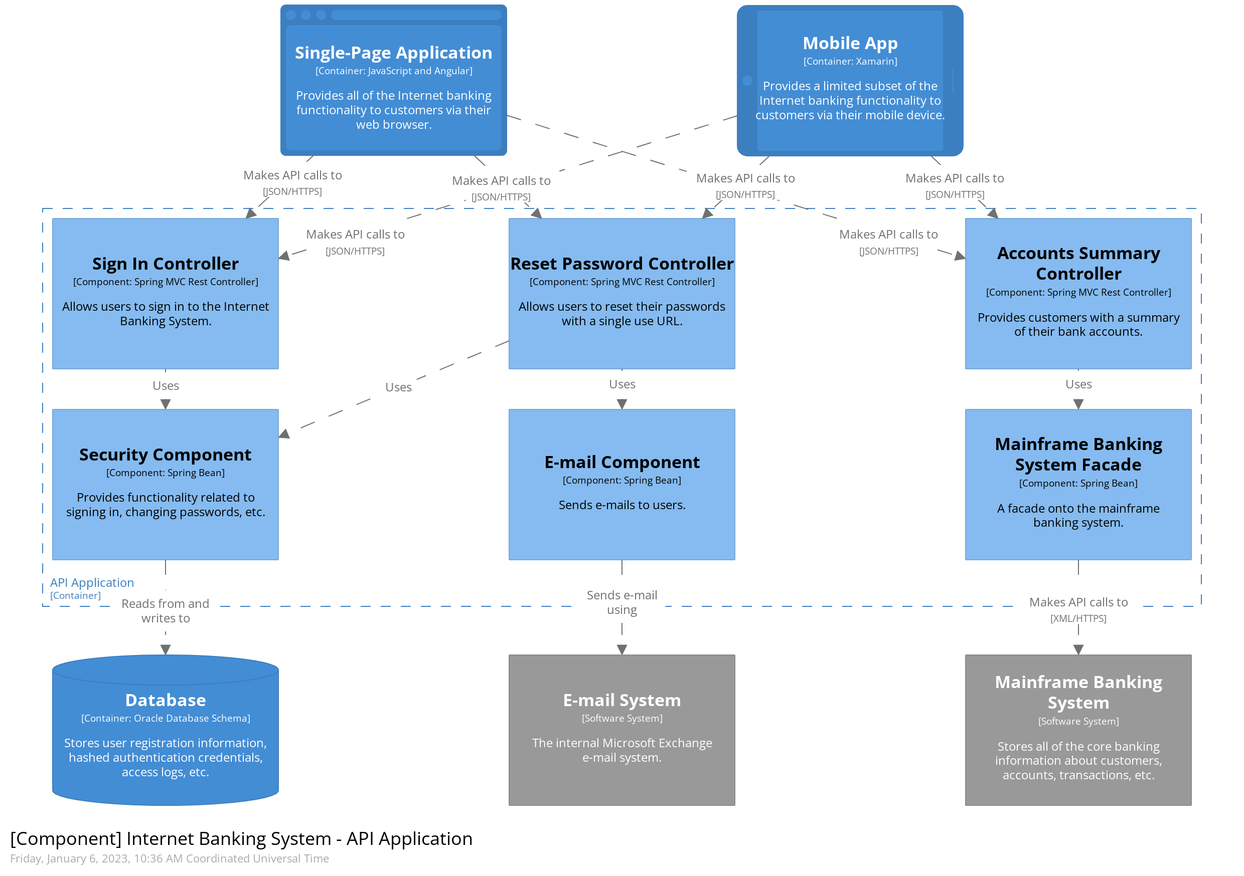
 Next you can zoom in and decompose each container further to identify the major structural building blocks and their interactions.
The Component diagram shows how a container is made up of a number of “components”, what each of those components are, their responsibilities and the technology/implementation details.
Level 4: Code
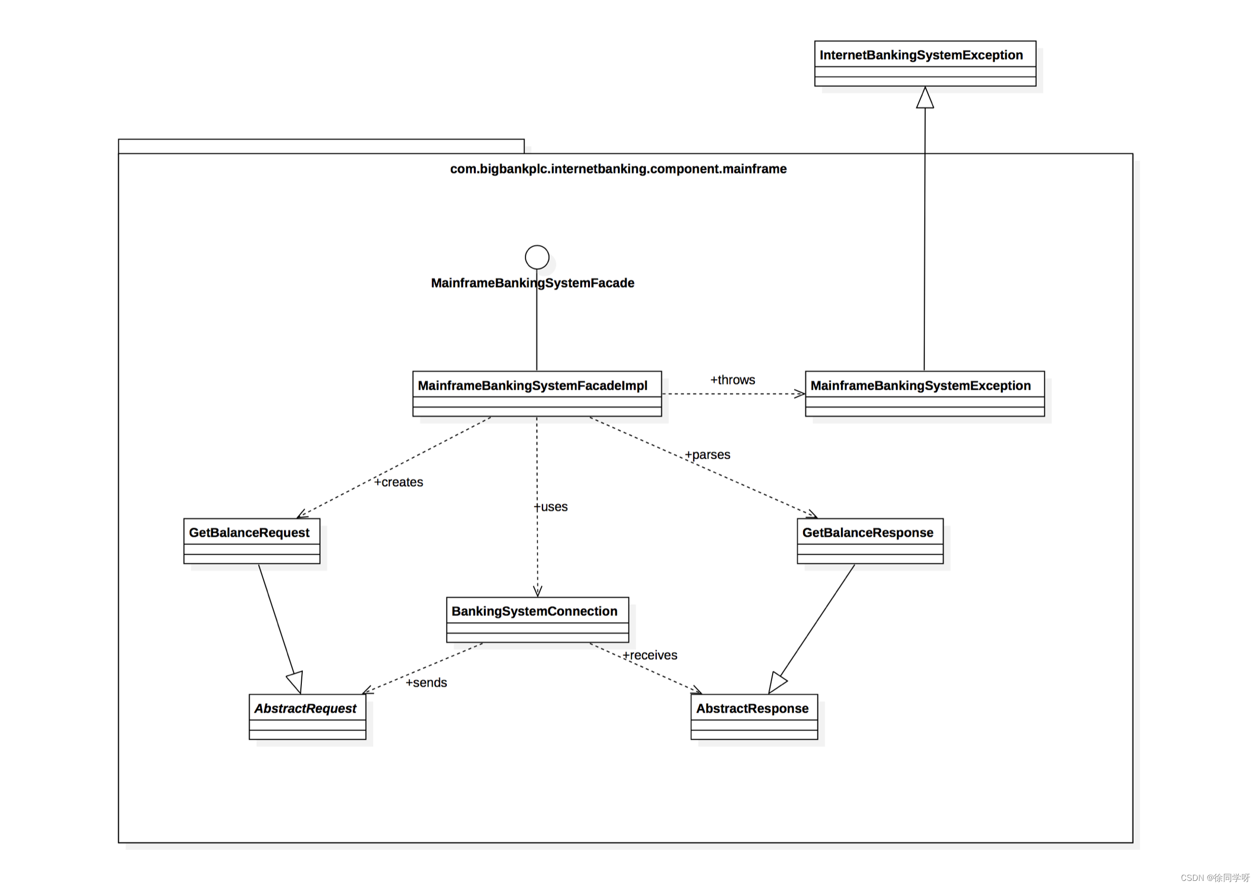
Finally, you can zoom in to each component to show how it is implemented as code; using UML class diagrams, entity relationship diagrams or similar.
This is an optional level of detail and is often available on-demand from tooling such as IDEs. Ideally this diagram would be automatically generated using tooling (e.g. an IDE or UML modelling tool), and you should consider showing only those attributes and methods that allow you to tell the story that you want to tell. This level of detail is not recommended for anything but the most important or complex components.
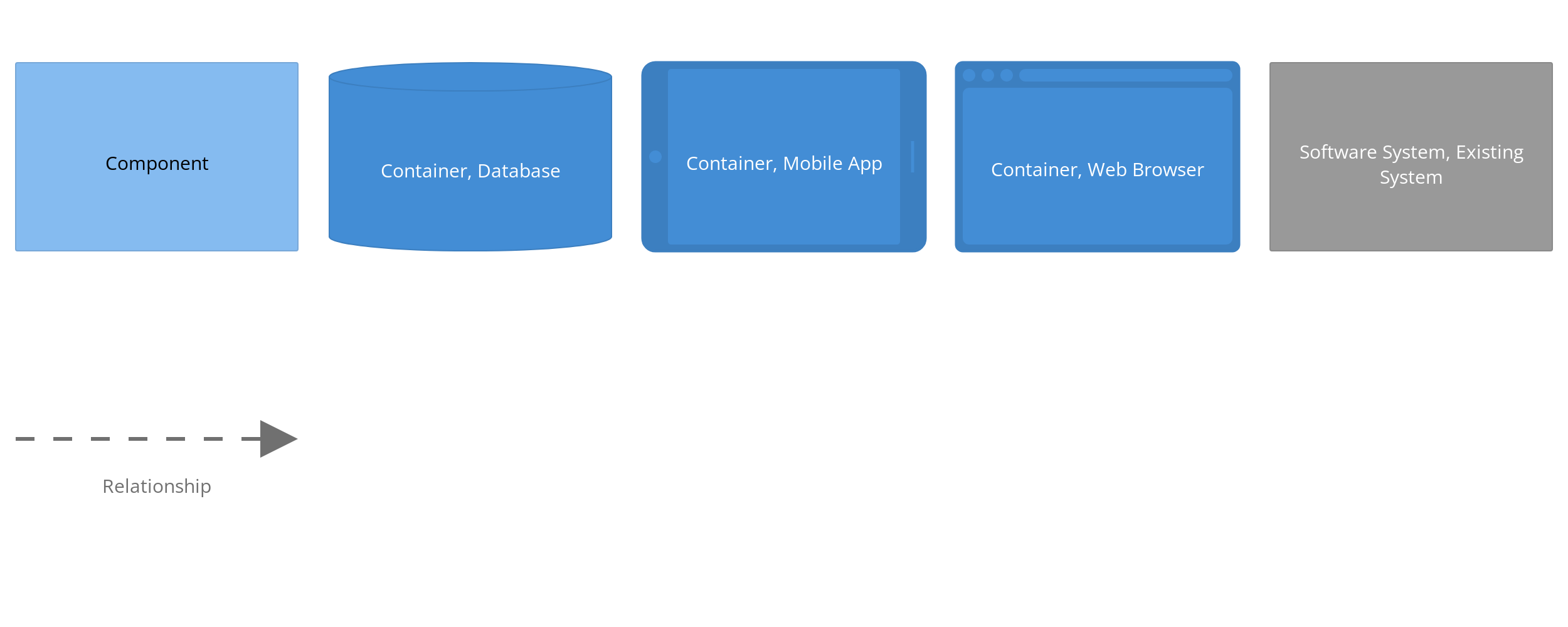
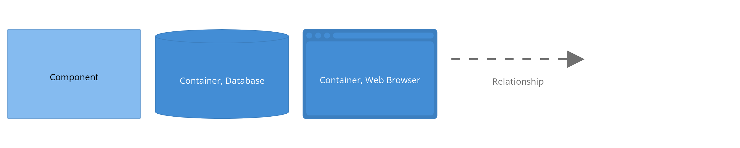
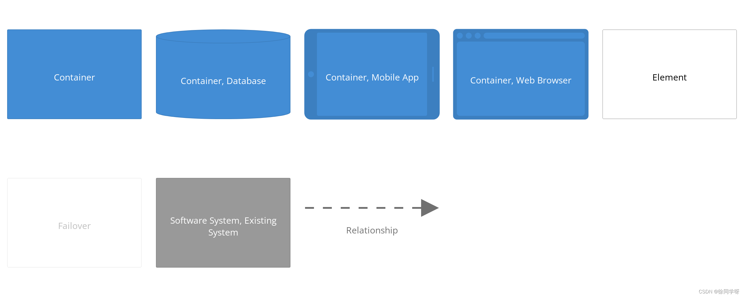
Notation
The C4 model doesn’t prescribe any particular notation. A simple notation that works well on whiteboards, paper, sticky notes, index cards and a variety of diagraming tools is as follows.
 Here are some recommendations related to notation:
Diagrams
- Every diagram should have a title describing the diagram type and scope (e.g. “System Context diagram for My Software System”).
- Every diagram should have a key/legend explaining the notation being used (e.g. shapes, colours, border styles, line types, arrow heads, etc).
- Acronyms and abbreviations (business/domain or technology) should be understandable by all audiences, or explained in the diagram key/legend.
Elements
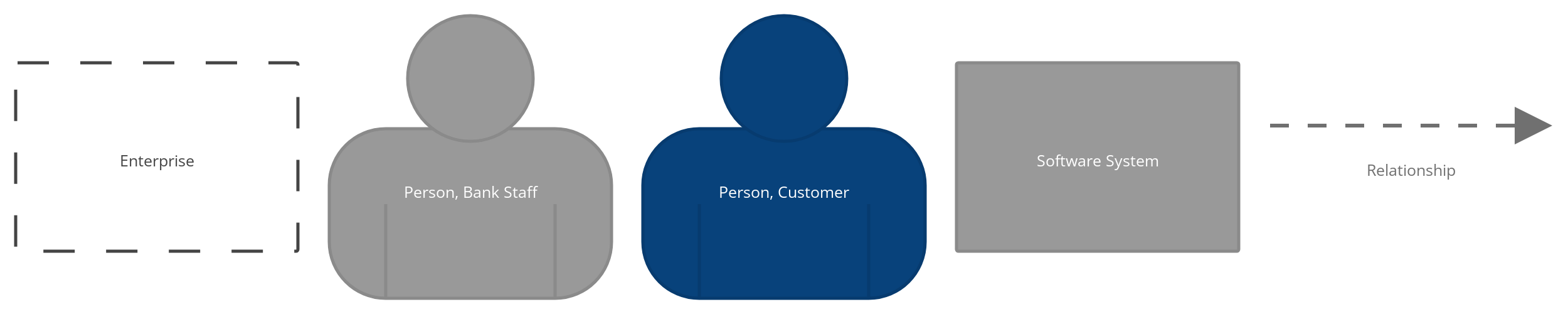
- The type of every element should be explicitly specified (e.g. Person, Software System, Container or Component).
- Every element should have a short description, to provide an “at a glance” view of key responsibilities.
- Every container and component should have a technology explicitly specified.
Relationships
- Every line should represent a unidirectional relationship.
- Every line should be labelled, the label being consistent with the direction and intent of the relationship (e.g. dependency or data flow). Try to be as specific as possible with the label, ideally avoiding single words like, “Uses”.
- Relationships between containers (typically these represent inter-process communication) should have a technology/protocol explicitly labelled.
Supplementary diagrams
System Landscape diagram
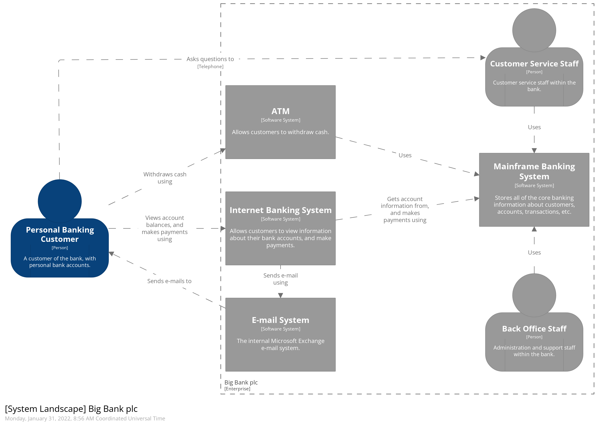
 The C4 model provides a static view of a single softwaresystem but, in the real-world, software systems never live in isolation. For this reason, and particularly if you are responsible for a collection of software systems, it’s often useful to understand how all of these software systems fit together within the bounds of an enterprise. To do this, simply add another diagram that sits “on top” of the C4 diagrams, to show the system landscape from an IT perspective. Like the System Context diagram, this diagram can show the organisational boundary, internal/external users and internal/external systems.
Essentially this is a high-level map of the software systems at the enterprise level, with a C4 drill-down for each software system of interest. From a practical perspective, a system landscape diagram is really just a system context diagram without a specific focus on a particular software system.
Dynamic diagram
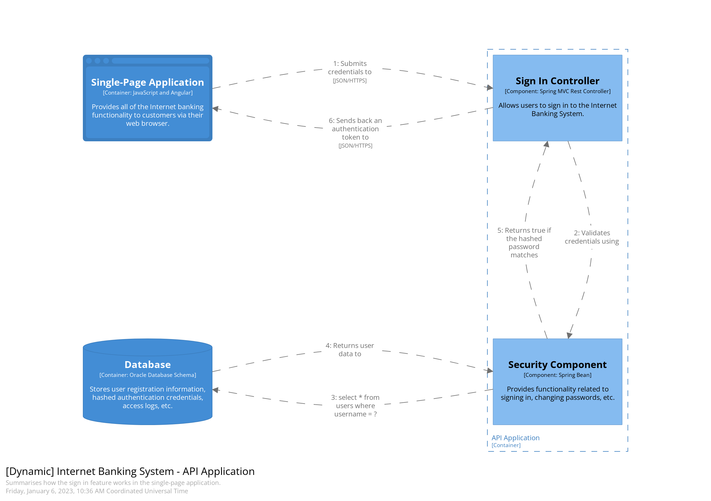
 A dynamic diagram can be useful when you want to show how elements in a static model collaborate at runtime to implement a user story, use case, feature, etc. This dynamic diagram is based upon a UML communication diagram(previously known as a “UML collaboration diagram”). It is similar to a UML sequence diagram although it allows a free-form arrangement of diagram elements with numbered interactions to indicate ordering.
Deployment diagram
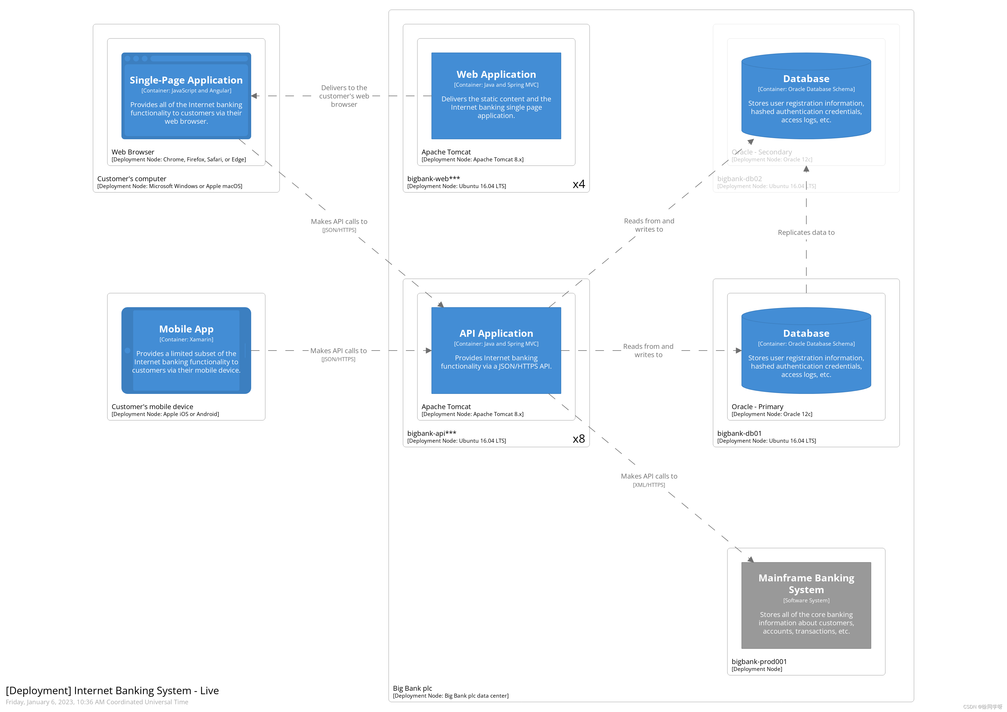
A deployment diagram allows you to illustrate how software systems and/or containers in the static model are mapped to infrastructure. This deployment diagram is based upon a UML deployment diagram, although simplified slightly to show the mapping between containers and deployment nodes. A deployment node is something like physical infrastructure (e.g. a physical server or device), virtualised infrastructure (e.g. IaaS, PaaS, a virtual machine), containerised infrastructure (e.g. a Docker container), an execution environment (e.g. a database server, Java EE web/application server, Microsoft IIS), etc. Deployment nodes can be nested.
You may also want to include infrastructure nodes such as DNS services, load balancers, firewalls, etc.
Tooling
Text-based modelling tools
Visual modelling tools
Text-based diagramming tools
Visual diagramming tools
原文整理:https://c4model.com/
工具推荐:


 736
736

 被折叠的 条评论
为什么被折叠?
被折叠的 条评论
为什么被折叠?
 到【灌水乐园】发言


