PCIE5.0规范学习(中文版)(3)

接上篇

PCIE5.0规范学习(中文版)(1)_pcie学习课程-CSDN博客

PCIE5.0规范学习(中文版)(2)_pcie培训文档-CSDN博客

目录

2.2.3 TLP Digest Rule

2.2.4 Routing and Addressing Rules

2.2.4.1 Address-Based Routing Rules

2.2.4.2 ID Based Routing Rules

2.2.5 第一/最后一个DW使能Rules

2.2.6 Transaction Descriptor事务描述符

2.2.6.1 Overview

2.2.6.2 事务描述符——事务ID域

2.2.6.3 事务描述符——属性

2.2.6.4 放松排序(Relaxed Ordering,RO)和基于ID的排序(ID-Based Ordering,IDO)

2.2.6.5 No Snoop属性

2.2.6.6 事务描述符——Traffic Class(TC)


2.2.3 TLP Digest Rule

  • 对任何TLP来说,TD中1b的值TLP摘要域的存在,包括TLP的末尾end-to-end的CRC值。
    • TD bit值与观察到的大小(计算data payload)不一致的TLP是畸形TLP
      • 这是与接收端有关的汇报错误
  • 如果TLP的中间或最终的PCIE接收机不支持ECRC检查,则接收机必须无视TLP摘要。
    • 如果TLP的接收方支持ECRC检查,接收机在TLP根据摘要规则,将TLP摘要域的值解释为ECRC值。

2.2.4 Routing and Addressing Rules

TLP路由有三条原则机制:地址、ID和隐式路由。本章定义了地址和ID路由的规则。隐式路由只用于Message请求,会在2.2.8中覆盖。

2.2.4.1 Address-Based Routing Rules
  • 地址路由用于内存和IO请求
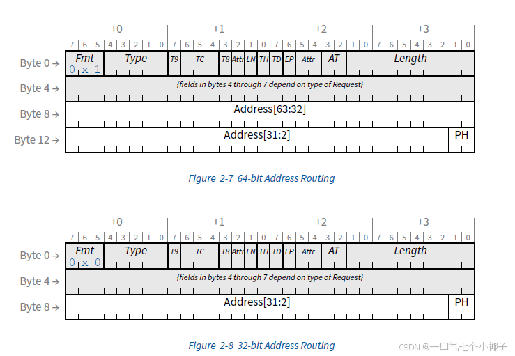
  • 具体描述了两种地址格式,64-bit格式使用4DW header和32-bit模式使用3DW header。

  • 对于内存读内存写和原子化操作请求,地址类型(AddressType,AT)域是被编码的表10-1编码的。对于所有其他的请求,AT域被保留除非明确的状态。轻量(LN)读和轻量写有具体的需求,见第六章。
  • 如果TH为1,则PH域编码见表2-15。如果TH为0,则PH域保留。
  • 地址映射到TLP header见表2-5

表2-5 地址域映射

Address bit

32-bit Addressing

64-bit Addressing

63:56

Not Applicable

Bits 7:0 of Byte 8

55:48

Not Applicable

Bits 7:0 of Byte 9

47:40

Not Applicable

Bits 7:0 of Byte 10

39:32

Not Applicable

Bits 7:0 of Byte 11

31:24

Bits 7:0 of Byte 8

Bits 7:0 of Byte 12

23:16

Bits 7:0 of Byte 9

Bits 7:0 of Byte 13

15:8

Bits 7:0 of Byte 10

Bits 7:0 of Byte 14

7:2

Bits 7:0 of Byte 11

Bits 7:0 of Byte 15

  • 内存读写和原子操作请求可以使用任何格式。
    • 对于小于4GB的地址,Requester必须使用32-bit格式。如果64-bit格式地址的请求地址小于4GB,则接收机的行为不会被指定(例:地址高32bits均为0)。
  • IO读请求和IO写请求使用32-bit格式。
  • 所有的Agent必须解码在header中的地址,不允许出现地址混叠。
2.2.4.2 ID Based Routing Rules
  • ID路由被用在配置请求、ID路由消息和完成中。本规范定义了一些ID路由消息(表F-1),其它规范被允许定义额外的ID路由消息。
  • ID路由使用总线、设备和Function号(如有)以指定TLP的目的地。
    • 对于非ARI路由ID,总线、设备和(3-bit)Function号到TLP header的映射见表2-6,图2-9及2-11。
    • 对于ARI路由ID,总线和(8-bit)Function号到TLP header的映射见表2-7,图2-10及图2-12。

表2-6 非ARI ID路由的header域布局

Field

Header位置

总线号Bus Number[7:0]

Byte8[7:0]

设备号Device Number[4:0]

Byte9[7:3]

Function号[2:0]

Byte9[2:0]

Traditional multi-drop, parallel bus technology is approaching its practical performance limits. It is clear that balancing system performance requires I/O bandwidth to scale with processing and application demands. There is an industry mandate to re-engineer I/O connectivity within cost constraints. PCI Express comprehends the many I/O requirements presented across the spectrum of computing and communications platforms, and rolls them into a common scalable and extensible I/O industry specification. Alongside these increasing performance demands, the enterprise server and communications markets have the need for improved reliability, security, and quality of service guarantees. This specification will therefore be applicable to multiple market segments. Technology advances in high-speed, point-to-point interconnects enable us to break away from the bandwidth limitations of multi-drop, parallel buses. The PCI Express basic physical layer consists of a differential transmit pair and a differential receive pair. Dual simplex data on these point-to-point connections is self-clocked and its bandwidth increases linearly with interconnect width and frequency. PCI Express takes an additional step of including a message space within its bus protocol that is used to implement legacy “side- band” signals. This further reduction of signal pins produces a very low pin count connection for components and adapters. The PCI Express Transaction, Data Link, and Physical Layers are optimized for chip-to-chip and board-to-board interconnect applications. An inherent limitation of today’s PCI-based platforms is the lack of support for isochronous data delivery, an attribute that is especially important to streaming media applications. To enable these emerging applications, PCI Express adds a virtual channel mechanism. In addition to use for support of isochronous traffic, the virtual channel mechanism provides an infrastructure for future extensions in supporting new applications. By adhering to the PCI Software Model, today’s applications are easily migrated even as emerging applications are enabled.
OBJECTIVE OF THE SPECIFICATION.................................................................................... 27 DOCUMENT ORGANIZATION ................................................................................................ 27 DOCUMENTATION CONVENTIONS...................................................................................... 28 TERMS AND ACRONYMS........................................................................................................ 29 REFERENCE DOCUMENTS...................................................................................................... 36 1. INTRODUCTION ................................................................................................................ 37 1.1. A THIRD GENERATION I/O INTERCONNECT ................................................................... 37 1.2. PCI EXPRESS LINK......................................................................................................... 39 1.3. PCI EXPRESS FABRIC TOPOLOGY .................................................................................. 41 1.3.1. Root Complex........................................................................................................ 41 1.3.2. Endpoints .............................................................................................................. 42 1.3.3. Switch.................................................................................................................... 45 1.3.4. Root Complex Event Collector.............................................................................. 46 1.3.5. PCI Express to PCI/PCI-X Bridge........................................................................ 46 1.4. PCI EXPRESS FABRIC TOPOLOGY CONFIGURATION....................................................... 46 1.5. PCI EXPRESS LAYERING OVERVIEW.............................................................................. 47 1.5.1. Transaction Layer................................................................................................. 48 1.5.2. Data Link Layer .................................................................................................... 48 1.5.3. Physical Layer ...................................................................................................... 49 1.5.4. Layer Functions and Services............................................................................... 49 2. TRANSACTION LAYER SPECIFICATION ..................................................................... 53 2.1. TRANSACTION LAYER OVERVIEW.................................................................................. 53 2.1.1. Address Spaces, Transaction Types, and Usage................................................... 54 2.1.2. Packet Format Overview ...................................................................................... 56 2.2. TRANSACTION LAYER PROTOCOL - PACKET DEFINITION............................................... 58 2.2.1. Common Packet Header Fields ............................................................................ 58 2.2.2. TLPs with Data Payloads - Rules ......................................................................... 61 2.2.3. TLP Digest Rules .................................................................................................. 65 2.2.4. Routing and Addressing Rules .............................................................................. 65 2.2.5. First/Last DW Byte Enables Rules........................................................................ 69 2.2.6. Transaction Descriptor......................................................................................... 71 2.2.7. Memory, I/O, and Configuration Request Rules................................................... 77 2.2.8. Message Request Rules......................................................................................... 83 2.2.9. Completion Rules.................................................................................................. 97 2.2.10. TLP Prefix Rules ................................................................................................. 100 2.3. HANDLING OF RECEIVED TLPS.................................................................................... 104
评论
添加红包

请填写红包祝福语或标题

红包个数最小为10个

红包金额最低5元

当前余额3.43前往充值 >
需支付:10.00
成就一亿技术人!
领取后你会自动成为博主和红包主的粉丝 规则
hope_wisdom
发出的红包

打赏作者

一口气七个小椰子

你的鼓励将是我创作的最大动力

¥1 ¥2 ¥4 ¥6 ¥10 ¥20
扫码支付:¥1
获取中
扫码支付

您的余额不足,请更换扫码支付或充值

打赏作者

实付
使用余额支付
点击重新获取
扫码支付
钱包余额 0

抵扣说明:

1.余额是钱包充值的虚拟货币,按照1:1的比例进行支付金额的抵扣。
2.余额无法直接购买下载,可以购买VIP、付费专栏及课程。

余额充值