


一、nRF52832 定时器基本介绍
nRF52832 包含了 5个定时器模块:

定时器有着不同的位宽选择,8/16/24/32位,通过BITMODE 寄存器的 第 0~1 位 选择:
 nRF52832 的定时器的内部结构:

1、时钟源
定时器工作在高频时钟源(HFLCK)下,包含了一个 4bit (1/2X)的分频器(Prescaler)。52832的有2种时钟输入模式,1MHz模式 和 16MHz模式。 时钟源通过分频器分频后输出最后的频率 f TIMER ,系统会通过这个参数自动选择时钟源,而不需要工程师设置寄存器。 当f TIMER > 1MHZ,系统自动选择16M时钟源,当F TIMER <= 1MHZ,系统选择1M时钟源。
2.分频器
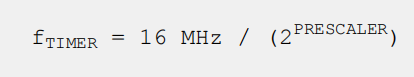
Prescaler 位 1bit 的分频器,其值为 0 ~ 15。当 Prescaler > 9时,其计算任然为 9:
 3、工作模式
 MODE: 0 选择定时器模式
MODE: 1 选择计数器模式
MODE: 2 选择低功耗计数器模式
定时器模式下,每一个时钟频率下,计数器自动加1;
技术模式下,每触发一次寄存器COUNT event,定时器内部计数器肌醇器就会加1。
4、比较/捕获功能
6个CC寄存器,下面是CC[1]:
 定时器模式下 :
设定CC[n]寄存器的值,可以设置定时的时间。
当定时时间的值和CC[n]寄存器的值相等时,将触发一个 COMPARE[n] event。 COMPARE[n] event可以触发中断。
如果是周期性的触发,则需要在触发后清除计数值,否则会一直计数,直到溢出。
计数器模式下:
每次触发 COUNT 任务时,TIMER 的内部计数器 Counter 寄存器都会递增 1 ,
计数器模式下是不使用定时器的频率 和 预分频器,COUNT 任务在定时器模式下无效。
通过设定一个CAPTURE Task,捕获的计数器的值存储到 CC[n] 寄存器内,然后对 CC[n] 寄存器进行读取计数器的值。
5.Task delays and Task priority
After the TIMER is started, the CLEAR task, COUNT task and the STOP task will guarantee to take effect
within one clock cycle of the PCLK16M.
If the START task and the STOP task are triggered at the same time, that is, within the same period of
PCLK16M, the STOP task will be prioritized.
二、nRF52832 定时器定时功能
定时器定时的使用(寄存器版本):
/*配置高速时钟*/
static volatile NRF_TIMER_Type * timer_init(timer_t timer)
{
    volatile NRF_TIMER_Type * p_timer;

    NRF_CLOCK->EVENTS_HFCLKSTARTED  = 0;
    NRF_CLOCK->TASKS_HFCLKSTART     = 1;//开启高速时钟
    // 等待外部振荡器启动
    while (NRF_CLOCK->EVENTS_HFCLKSTARTED == 0) {
    }
    switch (timer)
    {
        case TIMER0:
            p_timer = NRF_TIMER0;
            break;
        case TIMER1:
            p_timer = NRF_TIMER1;
            break;
        case TIMER2:
            p_timer = NRF_TIMER2;
            break;
        default:
            p_timer = 0;
            break;
    }
    return p_timer;
}
...
void nrf_timer_delay_ms(timer_t timer, uint_fast16_t volatile number_of_ms)
{
    volatile NRF_TIMER_Type * p_timer = timer_init(timer);

    if (p_timer == 0) {
    		printf("time init error!!");
    		break;
    }
		/*
		开始配置定时器
		时钟频率31250HZ,计1S需要31250次,计1ms需要31.25次
		*/
    p_timer->MODE           = TIMER_MODE_MODE_Timer;        // 设置为定时器模式
    p_timer->PRESCALER      = 9;                            // Prescaler 9 produces 31250 Hz timer frequency => 1 tick = 32 us.
    p_timer->BITMODE        = TIMER_BITMODE_BITMODE_16Bit;  // 16 bit 模式.
    p_timer->TASKS_CLEAR    = 1;                            // 清定时器.

    p_timer->CC[0]          = number_of_ms * 31; // cc里面的次数就是31.25次,先算整数部分,然后算小数部分
    p_timer->CC[0]         += number_of_ms / 4;
    p_timer->TASKS_START    = 1;                    // Start timer.

    while (p_timer->EVENTS_COMPARE[0] == 0) { //如果比较时间发生,退出循环,这里感觉直接在干等,不是很合理!!!
    }
    p_timer->EVENTS_COMPARE[0]  = 0;
    p_timer->TASKS_STOP         = 1;                // Stop timer.
}
定时器定时的使用(库函数版本):
...
 /*
配置定时器相关事件

相关的注释
typedef struct
{
    nrf_timer_frequency_t frequency;          ///< Frequency.
    nrf_timer_mode_t      mode;               ///< Mode of operation.
    nrf_timer_bit_width_t bit_width;          ///< Bit width.
    uint8_t               interrupt_priority; ///< Interrupt priority.
    void *                p_context;          ///< Context passed to interrupt handler.
} nrfx_timer_config_t;

#define NRF_DRV_TIMER_DEFAULT_CONFIG             NRFX_TIMER_DEFAULT_CONFIG
#define NRFX_TIMER_DEFAULT_CONFIG                                                    \
{                                                                                    \
    .frequency          = (nrf_timer_frequency_t)NRFX_TIMER_DEFAULT_CONFIG_FREQUENCY,\
    .mode               = (nrf_timer_mode_t)NRFX_TIMER_DEFAULT_CONFIG_MODE,          \
    .bit_width          = (nrf_timer_bit_width_t)NRFX_TIMER_DEFAULT_CONFIG_BIT_WIDTH,\
    .interrupt_priority = NRFX_TIMER_DEFAULT_CONFIG_IRQ_PRIORITY,                    \
    .p_context          = NULL                                                       \
}

const nrf_drv_timer_t TIMER_LED = NRF_DRV_TIMER_INSTANCE(0);
typedef nrfx_timer_t        nrf_drv_timer_t;
typedef struct
{
    NRF_TIMER_Type * p_reg;            ///< Pointer to the structure with TIMER peripheral instance registers.
    uint8_t          instance_id;      ///< Driver instance index.
    uint8_t          cc_channel_count; ///< Number of capture/compare channels.
} nrfx_timer_t;

#define NRF_DRV_TIMER_INSTANCE                   NRFX_TIMER_INSTANCE
#define NRFX_TIMER_INSTANCE(id)                                   \
{                                                                 \
    .p_reg            = NRFX_CONCAT_2(NRF_TIMER, id),             \
    .instance_id      = NRFX_CONCAT_3(NRFX_TIMER, id, _INST_IDX), \
    .cc_channel_count = NRF_TIMER_CC_CHANNEL_COUNT(id),           \
}

#define nrf_drv_timer_ms_to_ticks                nrfx_timer_ms_to_ticks

__STATIC_INLINE uint32_t nrfx_timer_ms_to_ticks(nrfx_timer_t const * const p_instance,
                                                uint32_t                   timer_ms)
{
    return nrf_timer_ms_to_ticks(timer_ms, nrf_timer_frequency_get(p_instance->p_reg));
}

// 16M 右移 分频器的值
__STATIC_INLINE uint32_t nrf_timer_ms_to_ticks(uint32_t time_ms,
                                               nrf_timer_frequency_t frequency)
{
    // The "frequency" parameter here is actually the prescaler value, and the
    // timer runs at the following frequency: f = 16000 kHz / 2^prescaler.
    uint32_t prescaler = (uint32_t)frequency;
    NRFX_ASSERT(time_ms <= (UINT32_MAX / 16000UL));
    return ((time_ms * 16000UL) >> prescaler);
}

#define nrf_drv_timer_extended_compare           nrfx_timer_extended_compare

void nrfx_timer_extended_compare(nrfx_timer_t const * const p_instance,
                                 nrf_timer_cc_channel_t     cc_channel,
                                 uint32_t                   cc_value,
                                 nrf_timer_short_mask_t     timer_short_mask,
                                 bool                       enable_int)
{
    nrf_timer_shorts_disable(p_instance->p_reg,
        (TIMER_SHORTS_COMPARE0_STOP_Msk  << cc_channel) |
        (TIMER_SHORTS_COMPARE0_CLEAR_Msk << cc_channel));

    nrf_timer_shorts_enable(p_instance->p_reg, timer_short_mask);

    nrfx_timer_compare(p_instance,
                       cc_channel,
                       cc_value,
                       enable_int);
    NRFX_LOG_INFO("Timer id: %d, capture value set: %lu, channel: %d.",
                  p_instance->instance_id,
                  cc_value,
                  cc_channel);
}

 */
 uint32_t time_ms = 1000; //定时器比较事件的时间
 uint32_t time_ticks;
 uint32_t err_code = NRF_SUCCESS;

 nrf_drv_timer_config_t timer_cfg = NRF_DRV_TIMER_DEFAULT_CONFIG;//使用的是默认配置,就是在sdk_config.h里面的配置
 err_code = nrf_drv_timer_init(&TIMER_LED, &timer_cfg, timer_led_event_handler);//timer_led_event_handler为定时器中断,需要额外实现的函数,TIMER_LED,是指使用的那个定时器
 APP_ERROR_CHECK(err_code);
 time_ticks = nrf_drv_timer_ms_to_ticks(&TIMER_LED, time_ms);//函数用于计算定时时间下 CC[n]寄存器的值。
 //触发定时器比较  nrf_drv_timer_extended_compare 用于使能定时器比较通道,使能比较中断,设置触发比较寄存器cc[n]等参数
 //time_ticks 由上面的语句可以算出来 31250
 //NRF_TIMER_SHORT_COMPARE0_CLEAR_MASK 定时器达到比较值以后,清除定时器技术的值清0,可以做到循环的计数
 nrf_drv_timer_extended_compare( &TIMER_LED, NRF_TIMER_CC_CHANNEL0, time_ticks, NRF_TIMER_SHORT_COMPARE0_CLEAR_MASK, true);
 //使能定时器
 nrf_drv_timer_enable(&TIMER_LED);
/*
 定时器中断
相关的注释
**
 * @brief Timer events.

typedef enum
{
    NRF_TIMER_EVENT_COMPARE0 = offsetof(NRF_TIMER_Type, EVENTS_COMPARE[0]), ///< Event from compare channel 0.
    NRF_TIMER_EVENT_COMPARE1 = offsetof(NRF_TIMER_Type, EVENTS_COMPARE[1]), ///< Event from compare channel 1.
    NRF_TIMER_EVENT_COMPARE2 = offsetof(NRF_TIMER_Type, EVENTS_COMPARE[2]), ///< Event from compare channel 2.
    NRF_TIMER_EVENT_COMPARE3 = offsetof(NRF_TIMER_Type, EVENTS_COMPARE[3]), ///< Event from compare channel 3.
#if defined(TIMER_INTENSET_COMPARE4_Msk) || defined(__NRFX_DOXYGEN__)
    NRF_TIMER_EVENT_COMPARE4 = offsetof(NRF_TIMER_Type, EVENTS_COMPARE[4]), ///< Event from compare channel 4.
#endif
#if defined(TIMER_INTENSET_COMPARE5_Msk) || defined(__NRFX_DOXYGEN__)
    NRF_TIMER_EVENT_COMPARE5 = offsetof(NRF_TIMER_Type, EVENTS_COMPARE[5]), ///< Event from compare channel 5.
#endif
} nrf_timer_event_t;

*/
void timer_led_event_handler(nrf_timer_event_t event_type, void* p_context)
{
    static uint32_t i;
    uint32_t led_to_invert = ((i++) % LEDS_NUMBER);
    switch (event_type)
    {
        case NRF_TIMER_EVENT_COMPARE0:
            bsp_board_led_invert(led_to_invert);
            break;
        default:
            break;
    }
}
三、nRF52832 定时器计数功能
定时器计数功能一般都是配置PPI使用,我们这里介绍使用主要给出简单的示例。
计数器模式下,每次触发 COPUNT 任务时, TIMER 的内部计数器 counter 都会递增 1。 但是计数器 counter 计数器内的值是无法读取的。 这时候需要通过设定一个 CAPTURE Task,捕获计数器 counter 的值 存储到 CC[n] 寄存器内, 然后在对 CC[n] 寄存器进行读取。
定时器计数的使用(寄存器版本):
void timer0_init(void)
{
    NRF_TIMER0->MODE    = TIMER_MODE_MODE_Counter;      // Set the timer in counter Mode.
    NRF_TIMER0->BITMODE = TIMER_BITMODE_BITMODE_24Bit;  // 24-bit mode.
}
...
//启动定时器
NRF_TIMER0->TASKS_START=1;
while(1){
...
 NRF_TIMER0->TASKS_COUNT         = 1; //手动启动计算
 NRF_TIMER0->TASKS_CAPTURE[0]    = 1; //启动捕获,计数器里的值放入CC[n]

 //获取计数值
 timVal = NRF_TIMER0->CC[0];
...
}
定时器计数的使用(库函数版本):
 void timer0_init(void)
{
	 uint32_t err_code = NRF_SUCCESS;
	  //定义定时器配置结构体,并使用默认配置参数初始化结构体
    nrfx_timer_config_t timer_cfg = NRFX_TIMER_DEFAULT_CONFIG;
	  //Timer0配置为计数模式
    timer_cfg.mode = NRF_TIMER_MODE_COUNTER;

	  //初始化定时器,定时器工作于计数模式时,没有事件,所以无需回调函数
   // err_code = nrfx_timer_init(&TIMER_COUNTER, &timer_cfg, my_timer_event_handler);
	  err_code = nrfx_timer_init(&TIMER_COUNTER, &timer_cfg, NULL);
    APP_ERROR_CHECK(err_code);
}

...
//启动定时器
nrfx_timer_enable(&TIMER_COUNTER);
while(1){
...
/* 计数器加1 */
nrfx_timer_increment(&TIMER_COUNTER);
//获取计数值
timVal = nrfx_timer_capture(&TIMER_COUNTER,NRF_TIMER_CC_CHANNEL0);
}


 2149
2149


 被折叠的 条评论
为什么被折叠?
被折叠的 条评论
为什么被折叠?
 到【灌水乐园】发言


