


RP2040 C SDK ADC功能使用
- 🌿RP2040 ADC功能说明文档:
https://www.raspberrypi.com/documentation/pico-sdk/hardware.html#hardware_adc
📗RP2040 ADC介绍
- SAR ADC
- 500 kS/s (Using an independent 48MHz clock)
- 12 bit (RP2040 8.7 ENOB, RP2350 9.2 ENOB)
- RP2040 5 input mux:
- 4 inputs that are available on package pins shared with GPIO[29:26]
- 1 input is dedicated to the internal temperature sensor
- 4 element receive sample FIFO。
- One input dedicated to the internal temperature sensor (see Section 12.4.6)
- Interrupt generation
- DMA interface

- 🍁相关电路:

📑RP2040 ADC API相关函数介绍
- 🌿
static inline void adc_select_input(uint input):配置输入通道:0 - 3分别对应GPIO26 - GPIO29。 - 🌿
static inline uint16_t adc_read(void):读取对应通道ADC转换结果。 - 🌿
static inline void adc_set_temp_sensor_enabled(bool enable):内部温度传感器使能位 - 🌿
static inline void adc_gpio_init(uint gpio):配置gpio模式作为ADC模拟输入模式。 - 🌿
static inline void adc_set_round_robin(uint input_mask):ADC通道选择位:0 - 4bit,值:0 - 1f,分别对应通道0-3,4:内部温度
如果多通道采样,需要配置adc下一个转换通道为3(GPIO29),那么
adc_set_round_robin(0x08);等同于adc_select_input(3)效果。
📜ADC通道和输入引脚
- 用户ADC输入在0 - 3通道(GPIO 26-29)上,共用一个ADC模数转换器,在多通道读取轮流读取。内部温度传感器在输入4通道上。
- 在
CMakeLists.txt配置文件中需要引入adc外设:
# Add the standard library to the build
target_link_libraries(RP2040_ADC
        pico_stdlib
        hardware_adc)
📘内部温度读取
/*
 CMSIS-DAP烧录命令:openocd -f interface/cmsis-dap.cfg -f target/rp2040.cfg -c  "adapter speed 5000"-c "program RP2040_ADC.elf verify reset exit"

 jlink命令: openocd -f interface/jlink.cfg -f target/rp2040.cfg  -c  "adapter speed 2000" -c  "program RP2040_ADC.elf verify reset exit"


*/
#include <stdio.h>
#include "pico/stdlib.h"
#include "hardware/gpio.h"
#include "hardware/divider.h"
#include "hardware/adc.h"
#include "hardware/clocks.h"

#define BUILTIN_LED PICO_DEFAULT_LED_PIN // LED is on the same pin as the default LED 25

/* Choose 'C' for Celsius or 'F' for Fahrenheit. */
#define TEMPERATURE_UNITS 'C'

static void measure_freqs(void);
/* References for this implementation:
 * raspberry-pi-pico-c-sdk.pdf, Section '4.1.1. hardware_adc'
 * pico-examples/adc/adc_console/adc_console.c */
float read_onboard_temperature(const char unit)
{

    /* 12-bit conversion, assume max value == ADC_VREF == 3.3 V */
    const float conversionFactor = 3.3f / (1 << 12);

    float adc = (float)adc_read() * conversionFactor;
    float tempC = 27.0f - (adc - 0.706f) / 0.001721f;

    if (unit == 'C')
    {
        return tempC;
    }
    else if (unit == 'F')
    {
        return tempC * 9 / 5 + 32;
    }

    return -1.0f;
}

int main()
{
    stdio_init_all();

    sleep_ms(2500);
    printf("adc test!\n");
    set_sys_clock_khz(133000, true); // 325us
   // GPIO initialisation.
    gpio_init(BUILTIN_LED);
    gpio_set_dir(BUILTIN_LED, 1);
    gpio_pull_up(BUILTIN_LED);

    adc_init();
    // 使能温度传感器
    adc_set_temp_sensor_enabled(true);
    adc_select_input(4);
    while (true)
    {
        // Read the temperature from the onboard temperature sensor.
        float temperature = read_onboard_temperature(TEMPERATURE_UNITS);
        printf("Onboard temperature = %.02f %c\n", temperature, TEMPERATURE_UNITS);
        sleep_ms(1000);
        gpio_xor_mask(1ul << BUILTIN_LED); // Toggle the LED
        // tight_loop_contents();
        measure_freqs();
    }

    return 0;
}

static void measure_freqs(void) {
    uint f_pll_sys = frequency_count_khz(CLOCKS_FC0_SRC_VALUE_PLL_SYS_CLKSRC_PRIMARY);
    uint f_pll_usb = frequency_count_khz(CLOCKS_FC0_SRC_VALUE_PLL_USB_CLKSRC_PRIMARY);
    uint f_rosc = frequency_count_khz(CLOCKS_FC0_SRC_VALUE_ROSC_CLKSRC);
    uint f_clk_sys = frequency_count_khz(CLOCKS_FC0_SRC_VALUE_CLK_SYS);
    uint f_clk_peri = frequency_count_khz(CLOCKS_FC0_SRC_VALUE_CLK_PERI);
    uint f_clk_usb = frequency_count_khz(CLOCKS_FC0_SRC_VALUE_CLK_USB);
    uint f_clk_adc = frequency_count_khz(CLOCKS_FC0_SRC_VALUE_CLK_ADC);
    uint f_clk_rtc = frequency_count_khz(CLOCKS_FC0_SRC_VALUE_CLK_RTC);

    printf("pll_sys  = %dkHz\n", f_pll_sys);
    printf("pll_usb  = %dkHz\n", f_pll_usb);
    printf("rosc     = %dkHz\n", f_rosc);
    printf("clk_sys  = %dkHz\n", f_clk_sys);
    printf("clk_peri = %dkHz\n", f_clk_peri);
    printf("clk_usb  = %dkHz\n", f_clk_usb);
    printf("clk_adc  = %dkHz\n", f_clk_adc);
    printf("clk_rtc  = %dkHz\n", f_clk_rtc);

    // Can't measure clk_ref / xosc as it is the ref
}
📗ADC单通道读取
/*
 CMSIS-DAP烧录命令:openocd -f interface/cmsis-dap.cfg -f target/rp2040.cfg -c  "adapter speed 5000"-c "program RP2040_ADC.elf verify reset exit"

 jlink命令: openocd -f interface/jlink.cfg -f target/rp2040.cfg  -c  "adapter speed 2000" -c  "program RP2040_ADC.elf verify reset exit"


*/
#include <stdio.h>
#include "pico/stdlib.h"
#include "hardware/gpio.h"
#include "hardware/divider.h"
#include "hardware/adc.h"
#include "hardware/clocks.h"

#define BUILTIN_LED PICO_DEFAULT_LED_PIN // LED is on the same pin as the default LED 25

static void measure_freqs(void);


void ADC_Reading(void)
{
    // 12-bit conversion, assume max value == ADC_VREF == 3.3 V
        const float conversion_factor = 3.3f / (1 << 12);
        uint16_t result = adc_read();
        printf("Raw value: 0x%03x, voltage: %f V\n", result, 3 * result * conversion_factor);
}


int main()
{
    stdio_init_all();

    sleep_ms(2500);
    printf("adc test!\n");
    set_sys_clock_khz(133000, true); // 325us
                                     // GPIO initialisation.
    gpio_init(BUILTIN_LED);
    gpio_set_dir(BUILTIN_LED, 1);
    gpio_pull_up(BUILTIN_LED);

    adc_init();
    // Make sure GPIO is high-impedance, no pullups etc
    adc_gpio_init(29);
    // Select ADC input 3 (GPIO29)
    adc_select_input(3);
    while (true)
    {

        sleep_ms(1000);
        gpio_xor_mask(1ul << BUILTIN_LED); // Toggle the LED
        // tight_loop_contents();
        measure_freqs();
        ADC_Reading();
    }

    return 0;
}

static void measure_freqs(void) {
    uint f_pll_sys = frequency_count_khz(CLOCKS_FC0_SRC_VALUE_PLL_SYS_CLKSRC_PRIMARY);
    uint f_pll_usb = frequency_count_khz(CLOCKS_FC0_SRC_VALUE_PLL_USB_CLKSRC_PRIMARY);
    uint f_rosc = frequency_count_khz(CLOCKS_FC0_SRC_VALUE_ROSC_CLKSRC);
    uint f_clk_sys = frequency_count_khz(CLOCKS_FC0_SRC_VALUE_CLK_SYS);
    uint f_clk_peri = frequency_count_khz(CLOCKS_FC0_SRC_VALUE_CLK_PERI);
    uint f_clk_usb = frequency_count_khz(CLOCKS_FC0_SRC_VALUE_CLK_USB);
    uint f_clk_adc = frequency_count_khz(CLOCKS_FC0_SRC_VALUE_CLK_ADC);
    uint f_clk_rtc = frequency_count_khz(CLOCKS_FC0_SRC_VALUE_CLK_RTC);

    printf("pll_sys  = %dkHz\n", f_pll_sys);
    printf("pll_usb  = %dkHz\n", f_pll_usb);
    printf("rosc     = %dkHz\n", f_rosc);
    printf("clk_sys  = %dkHz\n", f_clk_sys);
    printf("clk_peri = %dkHz\n", f_clk_peri);
    printf("clk_usb  = %dkHz\n", f_clk_usb);
    printf("clk_adc  = %dkHz\n", f_clk_adc);
    printf("clk_rtc  = %dkHz\n", f_clk_rtc);
}

📒多通道读取方式
由于ADC共用一个ADC模数转换器,在多通道读取时,,需要采用轮流配置通道读取方式。
void ADC_Reading(void)
{

    // 12-bit conversion, assume max value == ADC_VREF == 3.3 V
        const float conversion_factor = 3.3f / (1 << 12);
          adc_select_input(2);//设置通道2
        uint16_t adc_2_raw = adc_read();//读取转换通道转换结果
        adc_select_input(3);//设置通道3
        uint16_t adc_3_raw = adc_read();//读取转换通道转换结果
        printf("Raw1 value: 0x%03x, voltage: %f V\n", adc_2_raw, 3 * adc_2_raw * conversion_factor);
        printf("Raw2 value: 0x%03x, voltage: %f V\n", adc_3_raw, 3 * adc_3_raw * conversion_factor);
}
📒ADC 中断模式读取
ADC中断模式读取通道0(GPIO26)数据,数据存储模式和ADC DMA采集方式相同,需要建立一个ADC_FIFO缓冲区来存储。
/*
 CMSIS-DAP烧录命令:openocd -f interface/cmsis-dap.cfg -f target/rp2040.cfg -c  "adapter speed 5000"-c "program RP2040_Test.elf verify reset exit"

 jlink命令: openocd -f interface/jlink.cfg -f target/rp2040.cfg  -c  "adapter speed 2000" -c  "program RP2040_Test.elf verify reset exit"

    ADC通道:0 - 3  =》 ADC0 - ADC3  GPIO26 - GPIO29
    4通道A内部温度

*/

#include <stdio.h>
#include "pico/stdlib.h"
#include "hardware/uart.h"
#include "hardware/gpio.h"
#include "hardware/divider.h"
#include "hardware/adc.h"
#include "hardware/clocks.h"
#define BUILTIN_LED PICO_DEFAULT_LED_PIN // LED is on the same pin as the default LED 25

bool adc_irq_flag = false;
volatile uint16_t level;

#define SAMPLES 5
// Ideally the signal should be bandwidth limited to sample_frequency/2
#define SAMPLING_FREQUENCY 14000 // Sampling frequency in Hz

volatile  uint16_t sampleBuffer[SAMPLES];//ADC FIFO
static void ADC_IRQ_FIFO_Callback(void)
{
    level = adc_fifo_get_level();
    while (level-- > 0)
    {
        sampleBuffer[level] = adc_fifo_get();

    }
    adc_irq_flag = true;

}

void adc()
{
    adc_init();
    adc_gpio_init(26);
    //  adc_set_clkdiv(0); // 125kHz ADC clock
    // adc_set_temp_sensor_enabled(true);
    adc_select_input(0);
    //  adc_set_round_robin(0x0f); // ADC0, ADC1, ADC2, ADC3
    adc_set_round_robin(0b1);
    const uint32_t clock_hz = clock_get_hz(clk_adc);
    const uint32_t target_hz = 500;
    const float divider = 1.0f * clock_hz / target_hz;
    adc_set_clkdiv(divider);
 //adc_set_clkdiv((48000000/SAMPLING_FREQUENCY) - 1);
    //   sleep_ms(1000);
    irq_set_priority(ADC_IRQ_FIFO, PICO_HIGHEST_IRQ_PRIORITY); // Set the priority of the ADC IRQ
    irq_set_enabled(ADC_IRQ_FIFO, true);                       // Enable the ADC IRQ
    adc_fifo_setup(
        true,  // Write each completed conversion to the sample FIFO
        false, // Enable DMA data request (DREQ)
        SAMPLES,     // DREQ (and IRQ) asserted when at least 1 sample present
        false, // We won't see the ERR bit because of 8 bit reads; disable.
        // Shift each sample to 8 bits when pushing to FIFO [true] Changed to false for 12bit values
        false // Shift each sample to 8 bits when pushing to FIFO
    );
    irq_set_exclusive_handler(ADC_IRQ_FIFO, ADC_IRQ_FIFO_Callback); // Set the callback function for the ADC IRQ
    adc_irq_set_enabled(true);
//    adc_fifo_drain();
    adc_run(true);
}

int main()
{
    stdio_init_all();
    uart_init(uart0, 115200); // 115200 baud
    printf("adc test!\n");

    // set_sys_clock_khz(133000, true); // 325us
    // GPIO initialisation.
    gpio_init(BUILTIN_LED);
    gpio_set_dir(BUILTIN_LED, 1);
    gpio_pull_up(BUILTIN_LED);
    adc();
    while (true)
    { // Loop forever
        sleep_ms(1000);
        gpio_xor_mask(1ul << BUILTIN_LED); // Toggle the LED
        if (adc_irq_flag)
        {

    for (size_t  i = 0; i < SAMPLES; i++)
    {
       printf("  [%u]: %u", i, sampleBuffer[i]);
        if (i % SAMPLES == 4)
            printf("\n");
    }

            adc_irq_flag = false;
            //  sleep_ms(1000);
        }
    }

    return 0;
}

- 🌿在RP2040 IRQ中断配置项:
- 🔖中断优先级设置
- 🔖中断回调函数设置。
- 🔖在运行内核上开启对应中断。(
irq_set_enabled)- 🔖使能对应外设IRQ中断。
     irq_set_priority(ADC_IRQ_FIFO, PICO_HIGHEST_IRQ_PRIORITY); // Set the priority of the ADC IRQ
    irq_set_exclusive_handler(ADC_IRQ_FIFO, ADC_IRQ_FIFO_Callback);
    irq_set_enabled(ADC_IRQ_FIFO, true); // Enable the ADC IRQ.IRQ在执行核心上启用/禁用多个中断
    adc_irq_set_enabled(true); // Enable the ADC IRQ.
📓ADC 通过DMA方式读取
> - 🐛 目前程序有个bug问题:不管设置的dma传输字节大小为DMA_SIZE_8还是DMA_SIZE_16,DMA采样的ADC数据结果都一样。
🔰ADC通过DMA方式读取8位精度和12精度配置差异
- 至于为什么会有8位和12位精度问题,数据手册上有说明:
Sample FIFO
The ADC samples can be read directly from the RESULT register, or stored in a local 8-entry FIFO and read out from
FIFO. FIFO operation is controlled by the FCS register.
If FCS.EN is set, the result of each ADC conversion is written to the FIFO. A software interrupt handler or the RP2040
DMA can read this sample from the FIFO when notified by the ADC’s IRQ or DREQ signals. Alternatively, software can
poll the status bits in FCS to wait for each sample to become available.
If the FIFO is full when a conversion completes, the sticky error flag FCS.OVER is set. The current FIFO contents are not
changed by this event, but any conversion that completes whilst the FIFO is full will be lost.
There are two flags that control the data written to the FIFO by the ADC:
• FCS.SHIFT will right-shift the FIFO data to eight bits in size (i.e. FIFO bits 7:0 are conversion result bits 11:4). This
is suitable for 8-bit DMA transfer to a byte buffer in memory, allowing deeper capture buffers, at the cost of some
precision.
• FCS.ERR will set the FIFO.ERR flag
- 🌿ADC通过DMA方式读取8位精度
//ADC FIFO设置
   adc_fifo_setup(
        true,    // Write each completed conversion to the sample FIFO
        true,    // Enable DMA data request (DREQ)
        1,       // DREQ (and IRQ) asserted when at least 1 sample present
        false,   // We won't see the ERR bit because of 8 bit reads; disable.
        //Shift each sample to 8 bits when pushing to FIFO [true] Changed to false for 12bit values
        true// Shift each sample to 8 bits when pushing to FIFO
    );
- 🌿ADC通过DMA方式读取12位精度配置
//ADC FIFO设置
    adc_fifo_setup(
        true,    // Write each completed conversion to the sample FIFO
        true,    // Enable DMA data request (DREQ)
        1,       // DREQ (and IRQ) asserted when at least 1 sample present
        false,   // We won't see the ERR bit because of 8 bit reads; disable.
        //Shift each sample to 8 bits when pushing to FIFO [true] Changed to false for 12bit values
        false     // Shift each sample to 8 bits when pushing to FIFO
    );
- 📝ADC通过DMA方式读取8位精度代码
/*
 CMSIS-DAP烧录命令:openocd -f interface/cmsis-dap.cfg -f target/rp2040.cfg -c  "adapter speed 5000"-c "program RP2040_ADC_DMA.elf verify reset exit"

 jlink命令: openocd -f interface/jlink.cfg -f target/rp2040.cfg  -c  "adapter speed 2000" -c  "program RP2040_ADC_DMA.elf verify reset exit"


*/
#include <stdio.h>
#include "pico/stdlib.h"
#include "hardware/gpio.h"
#include "hardware/divider.h"
#include "hardware/adc.h"
#include "hardware/dma.h"
#include "hardware/clocks.h"
//#include "hardware/irq.h"
#define BUILTIN_LED PICO_DEFAULT_LED_PIN // LED is on the same pin as the default LED 25

// Channel 0 is GPIO26
#define CAPTURE_CHANNEL 0
#define SAMPLES 10
// Ideally the signal should be bandwidth limited to sample_frequency/2
#define SAMPLING_FREQUENCY 14000 // Sampling frequency in Hz

uint16_t sampleBuffer[SAMPLES];
uint16_t streamBuffer[SAMPLES]; // Scaled ADC sample working buffer

dma_channel_config cfg;
int dma_chan;


static void measure_freqs(void);


void ADC_Reading(void)
{

    // 12-bit conversion, assume max value == ADC_VREF == 3.3 V
        const float conversion_factor = 3.3f / (1 << 12);
          adc_select_input(0);//设置通道2
        uint16_t adc_0_raw = adc_read();//读取转换通道转换结果
        printf("Raw1 value:%d, voltage: %f V\n", adc_0_raw,adc_0_raw * conversion_factor);

}


int main()
{

    stdio_init_all();

    sleep_ms(2500);
    printf("adc DMA test!\n");
   // set_sys_clock_khz(133000, true); // 325us
                                     // GPIO initialisation.
    gpio_init(BUILTIN_LED);
    gpio_set_dir(BUILTIN_LED, 1);
    gpio_pull_up(BUILTIN_LED);

    adc_init();

    // Init GPIO for analogue use: hi-Z, no pulls, disable digital input buffer.
    adc_gpio_init(26 + CAPTURE_CHANNEL);
    //ADC_Reading();//1983
  //adc_set_round_robin(ADCopen==1 ? 1 : ADCopen==2 ? 3 : ADCopen==3 ? 7 : 15);
    adc_select_input(CAPTURE_CHANNEL);
    adc_fifo_setup(
        true,    // Write each completed conversion to the sample FIFO
        true,    // Enable DMA data request (DREQ)
        1,       // DREQ (and IRQ) asserted when at least 1 sample present
        false,   // We won't see the ERR bit because of 8 bit reads; disable.
        true     // Shift each sample to 8 bits when pushing to FIFO
    );

    // Divisor of 0 -> full speed. Free-running capture with the divider is
    // equivalent to pressing the ADC_CS_START_ONCE button once per `div + 1`
    // cycles (div not necessarily an integer). Each conversion takes 96
    // cycles, so
   // in general you want a divider of 0 (hold down the button
    // continuously) or > 95 (take samples less frequently than 96 cycle
    // intervals). This is all timed by the 48 MHz ADC clock.
    //adc_set_clkdiv((48000000/SAMPLING_FREQUENCY) - 1);
    adc_set_clkdiv(0);
  // Set up the DMA to start transferring data as soon as it appears in FIFO设置DMA,一旦数据出现在FIFO中就开始传输数据
  dma_chan = dma_claim_unused_channel(true);
  cfg = dma_channel_get_default_config(dma_chan);//获取给定通道的默认通道配置

  // Reading from constant address, writing to incrementing byte addresses
  channel_config_set_transfer_data_size(&cfg, DMA_SIZE_16);
  channel_config_set_read_increment(&cfg, false);//因为就一个地址永远地写到同一个位置,目的是循环触发同一个DMA.
  channel_config_set_write_increment(&cfg, true);//FIFO的地址自增

   channel_config_set_irq_quiet(&cfg, true);//在QUIET模式下,通道不会在每个传输块结束时产生irq。
    channel_config_set_dreq(&cfg, DREQ_ADC); // pace data according to ADC
    channel_config_set_chain_to(&cfg, dma_chan);//外设作为传输源,即ADC->DMA
    channel_config_set_enable(&cfg, true);

//设置DMA通道的配置,包括源地址、目的地址、传输字节数、传输方向、中断等。
//这里设置了源地址为ADC的FIFO,目的地址为streamBuffer,传输字节数为SAMPLES,传输方向为从ADC到streamBuffer,中断为DREQ_ADC。

  // Pace transfers based on availability of ADC samples
 // channel_config_set_dreq(&cfg, DREQ_ADC);

  dma_channel_configure(dma_chan, &cfg,
                        (uint16_t*)sampleBuffer,   // dst 数据存储到目标缓冲区
                        &adc_hw->fifo,  // src
                        SAMPLES,        // transfer count 传输数量,即采样点数
                        true            // start immediately
                       );
// Everything is ready to go. Tell the control channel to load the first
    // control block. Everything is automatic from here.
    dma_start_channel_mask(1u << dma_chan);// 开始传输

    printf("Starting capture\n");
    adc_run(true);// Start capture

    while (true)
    {
        // Read the temperature from the onboard temperature sensor.
      //  float temperature = read_onboard_temperature(TEMPERATURE_UNITS);
     //   printf("Onboard temperature = %.02f %c\n", temperature, TEMPERATURE_UNITS);
        sleep_ms(1000);
        gpio_xor_mask(1ul << BUILTIN_LED); // Toggle the LED
        // tight_loop_contents();
        measure_freqs();
        //ADC_Reading();
        // Wait for DMA to finish (may have already)
  dma_channel_wait_for_finish_blocking(dma_chan);

  // Stop and clean out FIFO
  adc_run(false);
  adc_fifo_drain();
  // Copy samples into buffer for approxFFT SAMPLES
  for (int i = 0; i < SAMPLES; i++) {

    streamBuffer[i] = sampleBuffer[i];
   // streamBuffer[i] = (uint16_t)((sampleBuffer[i]&0x0f)<<8)+(uint16_t)sampleBuffer[i+1] ;

    printf("%d ",streamBuffer[i]);
     if (i % 10 == 9)
            printf("\n");
   // sleep_ms(100);

  }

  sleep_ms(1000);
  dma_channel_set_trans_count(DREQ_ADC, 10, true);//设置DMA传输的字节数,这里是10个字节,即10个采样点。
  // Now we have a copy of the samples we can start capture again
  // dma_channel_configure(dma_chan, &cfg,
  //                       (uint16_t*)sampleBuffer,   // dst
  //                       &adc_hw->fifo,  // src
  //                       SAMPLES,        // transfer count
  //                       true            // start immediately
  //                      );

  // Restart the ADC capture
  adc_run(true);

    }

    return 0;
}

static void measure_freqs(void) {
    uint f_pll_sys = frequency_count_khz(CLOCKS_FC0_SRC_VALUE_PLL_SYS_CLKSRC_PRIMARY);
    uint f_pll_usb = frequency_count_khz(CLOCKS_FC0_SRC_VALUE_PLL_USB_CLKSRC_PRIMARY);
    uint f_rosc = frequency_count_khz(CLOCKS_FC0_SRC_VALUE_ROSC_CLKSRC);
    uint f_clk_sys = frequency_count_khz(CLOCKS_FC0_SRC_VALUE_CLK_SYS);
    uint f_clk_peri = frequency_count_khz(CLOCKS_FC0_SRC_VALUE_CLK_PERI);
    uint f_clk_usb = frequency_count_khz(CLOCKS_FC0_SRC_VALUE_CLK_USB);
    uint f_clk_adc = frequency_count_khz(CLOCKS_FC0_SRC_VALUE_CLK_ADC);
    uint f_clk_rtc = frequency_count_khz(CLOCKS_FC0_SRC_VALUE_CLK_RTC);

    printf("pll_sys  = %dkHz\n", f_pll_sys);
    printf("pll_usb  = %dkHz\n", f_pll_usb);
    printf("rosc     = %dkHz\n", f_rosc);
    printf("clk_sys  = %dkHz\n", f_clk_sys);
    printf("clk_peri = %dkHz\n", f_clk_peri);
    printf("clk_usb  = %dkHz\n", f_clk_usb);
    printf("clk_adc  = %dkHz\n", f_clk_adc);
    printf("clk_rtc  = %dkHz\n", f_clk_rtc);

    // Can't measure clk_ref / xosc as it is the ref
}

- 📝ADC通过DMA方式读取12位精度代码
/*
 CMSIS-DAP烧录命令:openocd -f interface/cmsis-dap.cfg -f target/rp2040.cfg -c  "adapter speed 5000"-c "program RP2040_ADC_DMA.elf verify reset exit"

 jlink命令: openocd -f interface/jlink.cfg -f target/rp2040.cfg  -c  "adapter speed 2000" -c  "program RP2040_ADC.elf verify reset exit"


*/
#include <stdio.h>
#include "pico/stdlib.h"
#include "hardware/gpio.h"
#include "hardware/divider.h"
#include "hardware/adc.h"
#include "hardware/dma.h"
#include "hardware/clocks.h"
#include "hardware/irq.h"
#define BUILTIN_LED PICO_DEFAULT_LED_PIN // LED is on the same pin as the default LED 25

// Channel 0 is GPIO26
#define CAPTURE_CHANNEL 0
#define SAMPLES 10
// Ideally the signal should be bandwidth limited to sample_frequency/2
#define SAMPLING_FREQUENCY 14000 // Sampling frequency in Hz

uint16_t sampleBuffer[SAMPLES];
uint16_t streamBuffer[SAMPLES]; // Scaled ADC sample working buffer

dma_channel_config cfg;
int dma_chan;

// const char src[] = "Hello, world! (from DMA)";
// char dst[count_of(src)];

static void measure_freqs(void);


void ADC_Reading(void)
{

    // 12-bit conversion, assume max value == ADC_VREF == 3.3 V
        const float conversion_factor = 3.3f / (1 << 12);
          adc_select_input(0);//设置通道2
        uint16_t adc_0_raw = adc_read();//读取转换通道转换结果
        printf("Raw1 value:%d, voltage: %f V\n", adc_0_raw,adc_0_raw * conversion_factor);

}


int main()
{

    stdio_init_all();

    sleep_ms(2500);
    printf("adc DMA test!\n");
   // set_sys_clock_khz(133000, true); // 325us
                                     // GPIO initialisation.
    gpio_init(BUILTIN_LED);
    gpio_set_dir(BUILTIN_LED, 1);
    gpio_pull_up(BUILTIN_LED);

    adc_init();

    // Init GPIO for analogue use: hi-Z, no pulls, disable digital input buffer.
    adc_gpio_init(26 + CAPTURE_CHANNEL);
    //ADC_Reading();//1983
  //adc_set_round_robin(ADCopen==1 ? 1 : ADCopen==2 ? 3 : ADCopen==3 ? 7 : 15);
    adc_select_input(CAPTURE_CHANNEL);
    adc_fifo_setup(
        true,    // Write each completed conversion to the sample FIFO
        true,    // Enable DMA data request (DREQ)
        1,       // DREQ (and IRQ) asserted when at least 1 sample present
        false,   // We won't see the ERR bit because of 8 bit reads; disable.
        //Shift each sample to 8 bits when pushing to FIFO [true] Changed to false for 12bit values
        false     // Shift each sample to 8 bits when pushing to FIFO
    );

    // Divisor of 0 -> full speed. Free-running capture with the divider is
    // equivalent to pressing the ADC_CS_START_ONCE button once per `div + 1`
    // cycles (div not necessarily an integer). Each conversion takes 96
    // cycles, so
   // in general you want a divider of 0 (hold down the button
    // continuously) or > 95 (take samples less frequently than 96 cycle
    // intervals). This is all timed by the 48 MHz ADC clock.
    //adc_set_clkdiv((48000000/SAMPLING_FREQUENCY) - 1);
    adc_set_clkdiv(0);
  // Set up the DMA to start transferring data as soon as it appears in FIFO设置DMA,一旦数据出现在FIFO中就开始传输数据
  dma_chan = dma_claim_unused_channel(true);
  cfg = dma_channel_get_default_config(dma_chan);//获取给定通道的默认通道配置

  // Reading from constant address, writing to incrementing byte addresses
  channel_config_set_transfer_data_size(&cfg, DMA_SIZE_16);
  channel_config_set_read_increment(&cfg, false);//因为就一个地址永远地写到同一个位置,目的是循环触发同一个DMA.
  channel_config_set_write_increment(&cfg, true);//FIFO的地址自增
//新增
   channel_config_set_irq_quiet(&cfg, true);//在QUIET模式下,通道不会在每个传输块结束时产生irq。
    channel_config_set_dreq(&cfg, DREQ_ADC); // pace data according to ADC
    channel_config_set_chain_to(&cfg, dma_chan);//外设作为传输源,即ADC->DMA
    channel_config_set_enable(&cfg, true);

//设置DMA通道的配置,包括源地址、目的地址、传输字节数、传输方向、中断等。
//这里设置了源地址为ADC的FIFO,目的地址为streamBuffer,传输字节数为SAMPLES,传输方向为从ADC到streamBuffer,中断为DREQ_ADC。

  // Pace transfers based on availability of ADC samples
 // channel_config_set_dreq(&cfg, DREQ_ADC);

  dma_channel_configure(dma_chan, &cfg,
                        sampleBuffer,   // dst (uint16_t*)数据存储到目标缓冲区
                        &adc_hw->fifo,  // src
                        SAMPLES,        // transfer count 传输数量,即采样点数
                        true            // start immediately
                       );
// Everything is ready to go. Tell the control channel to load the first
    // control block. Everything is automatic from here.
    dma_start_channel_mask(1u << dma_chan);// 开始传输

    printf("Starting capture\n");
    adc_run(true);// Start capture

    while (true)
    {
        // Read the temperature from the onboard temperature sensor.
      //  float temperature = read_onboard_temperature(TEMPERATURE_UNITS);
     //   printf("Onboard temperature = %.02f %c\n", temperature, TEMPERATURE_UNITS);
        sleep_ms(1000);
        gpio_xor_mask(1ul << BUILTIN_LED); // Toggle the LED
        // tight_loop_contents();
        measure_freqs();
        //ADC_Reading();
        // Wait for DMA to finish (may have already)
  dma_channel_wait_for_finish_blocking(dma_chan);

  // Stop and clean out FIFO
  adc_run(false);
  adc_fifo_drain();
  // Copy samples into buffer for approxFFT SAMPLES
  for (int i = 0; i < SAMPLES; i++) {

    printf("%-3d ",sampleBuffer[i]);
     if (i % 10 == 9)
            printf("\n");
   // sleep_ms(100);

  }
  // SUM_VALUE/=SAMPLES;
  // printf("SUM_VALUE = %d\n",SUM_VALUE);
  // SUM_VALUE = 0;
  sleep_ms(1000);
 // dma_channel_set_trans_count(DREQ_ADC, 10, true);//设置DMA传输的字节数,这里是10个字节,即10个采样点。
  //Now we have a copy of the samples we can start capture again
  dma_channel_configure(dma_chan, &cfg,
                        (uint16_t*)sampleBuffer,   // dst
                        &adc_hw->fifo,  // src
                        SAMPLES,        // transfer count
                        true            // start immediately
                       );

  // Restart the ADC capture
  adc_run(true);

    }

    return 0;
}

static void measure_freqs(void) {
    uint f_pll_sys = frequency_count_khz(CLOCKS_FC0_SRC_VALUE_PLL_SYS_CLKSRC_PRIMARY);
    uint f_pll_usb = frequency_count_khz(CLOCKS_FC0_SRC_VALUE_PLL_USB_CLKSRC_PRIMARY);
    uint f_rosc = frequency_count_khz(CLOCKS_FC0_SRC_VALUE_ROSC_CLKSRC);
    uint f_clk_sys = frequency_count_khz(CLOCKS_FC0_SRC_VALUE_CLK_SYS);
    uint f_clk_peri = frequency_count_khz(CLOCKS_FC0_SRC_VALUE_CLK_PERI);
    uint f_clk_usb = frequency_count_khz(CLOCKS_FC0_SRC_VALUE_CLK_USB);
    uint f_clk_adc = frequency_count_khz(CLOCKS_FC0_SRC_VALUE_CLK_ADC);
    uint f_clk_rtc = frequency_count_khz(CLOCKS_FC0_SRC_VALUE_CLK_RTC);

    printf("pll_sys  = %dkHz\n", f_pll_sys);
    printf("pll_usb  = %dkHz\n", f_pll_usb);
    printf("rosc     = %dkHz\n", f_rosc);
    printf("clk_sys  = %dkHz\n", f_clk_sys);
    printf("clk_peri = %dkHz\n", f_clk_peri);
    printf("clk_usb  = %dkHz\n", f_clk_usb);
    printf("clk_adc  = %dkHz\n", f_clk_adc);
    printf("clk_rtc  = %dkHz\n", f_clk_rtc);

    // Can't measure clk_ref / xosc as it is the ref
}

📙ADC 通过DMA IRQ方式读取
通过DMA中断方式读取ADC采集数据。
/*
 CMSIS-DAP烧录命令:openocd -f interface/cmsis-dap.cfg -f target/rp2040.cfg -c  "adapter speed 5000"-c "program RP2040_ADC_DMA_IRQ.elf verify reset exit"

 jlink命令: openocd -f interface/jlink.cfg -f target/rp2040.cfg  -c  "adapter speed 2000" -c  "program RP2040_ADC_DMA_IRQ.elf verify reset exit"


*/
#include <stdio.h>
#include "pico/stdlib.h"
#include "hardware/gpio.h"
#include "hardware/divider.h"
#include "hardware/adc.h"
#include "hardware/dma.h"
#include "hardware/clocks.h"
#include "hardware/irq.h"

#define BUILTIN_LED PICO_DEFAULT_LED_PIN // LED is on the same pin as the default LED 25

// Channel 0 is GPIO26
#define CAPTURE_CHANNEL 0
#define SAMPLES 10
// Ideally the signal should be bandwidth limited to sample_frequency/2
#define SAMPLING_FREQUENCY 14000 // Sampling frequency in Hz

uint16_t sampleBuffer[SAMPLES];
uint16_t streamBuffer[SAMPLES]; // Scaled ADC sample working buffer

dma_channel_config cfg;
volatile int dma_chan;

volatile bool dma_done = false; // Flag to indicate DMA transfer is complete

// const char src[] = "Hello, world! (from DMA)";
// char dst[count_of(src)];

static void measure_freqs(void);


void ADC_Reading(void)
{

    // 12-bit conversion, assume max value == ADC_VREF == 3.3 V
        const float conversion_factor = 3.3f / (1 << 12);
          adc_select_input(0);//设置通道2
        uint16_t adc_0_raw = adc_read();//读取转换通道转换结果
        printf("Raw1 value:%d, voltage: %f V\n", adc_0_raw,adc_0_raw * conversion_factor);

}

void dma_handler() {

    dma_done = true;
      // Stop and clean out FIFO
  adc_run(false);
  adc_fifo_drain();

//   Clear the interrupt request.
  dma_hw->ints0 = 1u << dma_chan; // Clear the interrupt request.

   // dma_channel_set_read_addr(dma_chan, &sampleBuffer, true);
  //  dma_channel_set_trans_count(dma_chan, SAMPLES, true);


}

int main()
{

    stdio_init_all();

    sleep_ms(2500);
    printf("adc DMA test!\n");
   // set_sys_clock_khz(133000, true); // 325us
                                     // GPIO initialisation.
    gpio_init(BUILTIN_LED);
    gpio_set_dir(BUILTIN_LED, 1);
    gpio_pull_up(BUILTIN_LED);

    adc_init();

    // Init GPIO for analogue use: hi-Z, no pulls, disable digital input buffer.
    adc_gpio_init(26 + CAPTURE_CHANNEL);
    //ADC_Reading();//1983
  //adc_set_round_robin(ADCopen==1 ? 1 : ADCopen==2 ? 3 : ADCopen==3 ? 7 : 15);
    adc_select_input(CAPTURE_CHANNEL);
    adc_fifo_setup(
        true,    // Write each completed conversion to the sample FIFO
        true,    // Enable DMA data request (DREQ)
        1,       // DREQ (and IRQ) asserted when at least 1 sample present
        false,   // We won't see the ERR bit because of 8 bit reads; disable.
        //Shift each sample to 8 bits when pushing to FIFO [true] Changed to false for 12bit values
        false     // Shift each sample to 8 bits when pushing to FIFO
    );

    // Divisor of 0 -> full speed. Free-running capture with the divider is
    // equivalent to pressing the ADC_CS_START_ONCE button once per `div + 1`
    // cycles (div not necessarily an integer). Each conversion takes 96
    // cycles, so
   // in general you want a divider of 0 (hold down the button
    // continuously) or > 95 (take samples less frequently than 96 cycle
    // intervals). This is all timed by the 48 MHz ADC clock.
    //adc_set_clkdiv((48000000/SAMPLING_FREQUENCY) - 1);
    adc_set_clkdiv(0);
  // Set up the DMA to start transferring data as soon as it appears in FIFO设置DMA,一旦数据出现在FIFO中就开始传输数据
  dma_chan = dma_claim_unused_channel(true);
  cfg = dma_channel_get_default_config(dma_chan);//获取给定通道的默认通道配置

  // Reading from constant address, writing to incrementing byte addresses
  channel_config_set_transfer_data_size(&cfg, DMA_SIZE_16);
  channel_config_set_read_increment(&cfg, false);//因为就一个地址永远地写到同一个位置,目的是循环触发同一个DMA.
  channel_config_set_write_increment(&cfg, true);//FIFO的地址自增

  // channel_config_set_irq_quiet(&cfg, true);//在QUIET模式下,通道不会在每个传输块结束时产生irq。
  channel_config_set_irq_quiet(&cfg, false);在非QUIET模式下,通道在每个传输块结束时产生irq。

  // Tell the DMA to raise IRQ line 0 when the channel finishes a block
dma_channel_set_irq0_enabled(dma_chan, true);
     // Configure the processor to run dma_handler() when DMA IRQ 0 is asserted
    irq_set_exclusive_handler(DMA_IRQ_0, dma_handler);
    irq_set_enabled(DMA_IRQ_0, true);

    channel_config_set_dreq(&cfg, DREQ_ADC); // pace data according to ADC
    channel_config_set_chain_to(&cfg, dma_chan);//外设作为传输源,即ADC->DMA
    channel_config_set_enable(&cfg, true);

//设置DMA通道的配置,包括源地址、目的地址、传输字节数、传输方向、中断等。
//这里设置了源地址为ADC的FIFO,目的地址为streamBuffer,传输字节数为SAMPLES,传输方向为从ADC到streamBuffer,中断为DREQ_ADC。

  // Pace transfers based on availability of ADC samples
 // channel_config_set_dreq(&cfg, DREQ_ADC);

  dma_channel_configure(dma_chan, &cfg,
                        sampleBuffer,   // dst (uint16_t*)数据存储到目标缓冲区
                        &adc_hw->fifo,  // src
                        SAMPLES,        // transfer count 传输数量,即采样点数
                        true            // start immediately
                       );
// Everything is ready to go. Tell the control channel to load the first
    // control block. Everything is automatic from here.
    dma_start_channel_mask(1u << dma_chan);// 开始传输

    printf("Starting capture\n");
    adc_run(true);// Start capture

    while (true)
    {
        // Read the temperature from the onboard temperature sensor.
      //  float temperature = read_onboard_temperature(TEMPERATURE_UNITS);
     //   printf("Onboard temperature = %.02f %c\n", temperature, TEMPERATURE_UNITS);
        sleep_ms(1000);
        gpio_xor_mask(1ul << BUILTIN_LED); // Toggle the LED
        // tight_loop_contents();
        measure_freqs();
        //ADC_Reading();
        // Wait for DMA to finish (may have already)
 // dma_channel_wait_for_finish_blocking(dma_chan);

if (dma_done) {
    dma_done = false;
    // Stop and clean out FIFO
    adc_run(false);
    adc_fifo_drain();
    // Read the ADC samples from the DMA channel

  for (int i = 0; i < SAMPLES; i++) {

    printf("%-3d ",sampleBuffer[i]);
     if (i % 10 == 9)
            printf("\n");
   // sleep_ms(100);

  }
    //Now we have a copy of the samples we can start capture again
  dma_channel_configure(dma_chan, &cfg,
                        (uint16_t*)sampleBuffer,   // dst
                        &adc_hw->fifo,  // src
                        SAMPLES,        // transfer count
                        true            // start immediately
                       );

  // Restart the ADC capture
  adc_run(true);
}
  sleep_ms(1000);

    }

    return 0;
}

static void measure_freqs(void) {
    uint f_pll_sys = frequency_count_khz(CLOCKS_FC0_SRC_VALUE_PLL_SYS_CLKSRC_PRIMARY);
    uint f_pll_usb = frequency_count_khz(CLOCKS_FC0_SRC_VALUE_PLL_USB_CLKSRC_PRIMARY);
    uint f_rosc = frequency_count_khz(CLOCKS_FC0_SRC_VALUE_ROSC_CLKSRC);
    uint f_clk_sys = frequency_count_khz(CLOCKS_FC0_SRC_VALUE_CLK_SYS);
    uint f_clk_peri = frequency_count_khz(CLOCKS_FC0_SRC_VALUE_CLK_PERI);
    uint f_clk_usb = frequency_count_khz(CLOCKS_FC0_SRC_VALUE_CLK_USB);
    uint f_clk_adc = frequency_count_khz(CLOCKS_FC0_SRC_VALUE_CLK_ADC);
    uint f_clk_rtc = frequency_count_khz(CLOCKS_FC0_SRC_VALUE_CLK_RTC);

    printf("pll_sys  = %dkHz\n", f_pll_sys);
    printf("pll_usb  = %dkHz\n", f_pll_usb);
    printf("rosc     = %dkHz\n", f_rosc);
    printf("clk_sys  = %dkHz\n", f_clk_sys);
    printf("clk_peri = %dkHz\n", f_clk_peri);
    printf("clk_usb  = %dkHz\n", f_clk_usb);
    printf("clk_adc  = %dkHz\n", f_clk_adc);
    printf("clk_rtc  = %dkHz\n", f_clk_rtc);

    // Can't measure clk_ref / xosc as it is the ref
}
📓raspberrypi/pico-examples/adc_console例程使用介绍
adc_console例程,一个基于 Raspberry Pi Pico 的 ADC(模数转换器)控制台示例程序,用于与 ADC 进行交互,它提供了一个简单的命令行界面来控制 ADC 的操作。
- adc_console例程代码:
/*
  CMSIS-DAP烧录命令:openocd -f interface/cmsis-dap.cfg -f target/rp2040.cfg -c  "adapter speed 5000"-c "program adc_console.elf verify reset exit"

 jlink命令: openocd -f interface/jlink.cfg -f target/rp2040.cfg  -c  "adapter speed 2000" -c  "program adc_console.elf verify reset exit"
 */
#include <stdio.h>
#include "pico/stdlib.h"
#include "hardware/gpio.h"
#include "hardware/adc.h"

#define N_SAMPLES 1000
uint16_t sample_buf[N_SAMPLES];

void printhelp() {
    puts("\nCommands:");
    puts("c0, ...\t: Select ADC channel n");
    puts("s\t: Sample once");
    puts("S\t: Sample many");
    puts("w\t: Wiggle pins");
}

void __not_in_flash_func(adc_capture)(uint16_t *buf, size_t count) {
    adc_fifo_setup(true, false, 0, false, false);
    adc_run(true);
    for (size_t i = 0; i < count; i = i + 1)
        buf[i] = adc_fifo_get_blocking();
    adc_run(false);
    adc_fifo_drain();
}

int main(void) {
    stdio_init_all();
    adc_init();
    adc_set_temp_sensor_enabled(true);

    // Set all pins to input (as far as SIO is concerned)
    gpio_set_dir_all_bits(0);
    for (int i = 2; i < 30; ++i) {
        gpio_set_function(i, GPIO_FUNC_SIO);
        if (i >= 26) {
            gpio_disable_pulls(i);
            gpio_set_input_enabled(i, false);
        }
    }

    printf("\n===========================\n");
    printf("RP2040 ADC and Test Console\n");
    printf("===========================\n");
    printhelp();

    while (1) {
        char c = getchar();
        printf("%c", c);
        switch (c) {
            case 'c':
                c = getchar();
                printf("%c\n", c);
                if (c < '0' || c > '7') {
                    printf("Unknown input channel\n");
                    printhelp();
                } else {
                    adc_select_input(c - '0');
                    printf("Switched to channel %c\n", c);
                }
                break;
            case 's': {
                uint32_t result = adc_read();
                const float conversion_factor = 3.3f / (1 << 12);
                printf("\n0x%03x -> %f V\n", result, result * conversion_factor);
                break;
            }
            case 'S': {
                printf("\nStarting capture\n");
                adc_capture(sample_buf, N_SAMPLES);
                printf("Done\n");
                for (int i = 0; i < N_SAMPLES; i = i + 1)
                    printf("%03x\n", sample_buf[i]);
                break;
            }
            case 'w': {
                printf("\nPress any key to stop wiggling\n");
                int i = 1;
                gpio_set_dir_all_bits(-1);
                while (getchar_timeout_us(0) == PICO_ERROR_TIMEOUT) {
                    // Pattern: Flash all pins for a cycle,
                    // Then scan along pins for one cycle each
                    i = i ? i << 1 : 1;
                    gpio_put_all(i ? i : ~0);
                     // 调用延时函数,这里设置为500毫秒,可以根据需要调整
                    sleep_ms(500);
                }
                gpio_set_dir_all_bits(0);
                printf("Wiggling halted.\n");
                break;
            }
            case '\n':
            case '\r':
                break;
            case 'h':
                printhelp();
                break;
            default:
                printf("\nUnrecognised command: %c\n", c);
                printhelp();
                break;
        }
    }
}
📑使用命令行界面
程序启动后,会显示一个命令行界面,你可以输入以下命令来控制 ADC 的操作:
- 查看帮助信息
输入 h 并回车,程序会显示可用的命令列表:
Commands:
c0, ...  : Select ADC channel n
s        : Sample once
S        : Sample many
w        : Wiggle pins
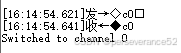
- 选择 ADC 通道
输入 c 后跟一个数字(0-7),例如 c0 ,程序会切换到指定的 ADC 通道。如果输入的数字不在 0-7 范围内,会显示错误信息并再次显示帮助信息。
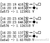
- 单次采样
输入 s 并回车,程序会对当前选择的 ADC 通道进行一次采样,并显示采样结果(以十六进制和电压值表示)。
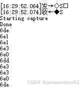
- 多次采样
输入 S 并回车,程序会开始对当前选择的 ADC 通道进行多次采样(采样次数由 N_SAMPLES 定义),并将采样结果以十六进制形式依次显示。
- 引脚闪烁
输入 w 并回车,程序会使所有 GPIO 引脚开始闪烁,直到发送任意字符停止。


 1940
1940

 被折叠的 条评论
为什么被折叠?
被折叠的 条评论
为什么被折叠?
 到【灌水乐园】发言


