


RP2040 C SDK clocks时钟源配置使用
-
🌿RP2040时钟源API函数文档:
https://www.raspberrypi.com/documentation/pico-sdk/hardware.html#group_hardware_clocks -
🍁RP2040时钟树:

系统时钟源可以来自外部时钟输入(external clocks)、 晶体振荡器(XOSC)或者经过晶体振荡器到USB时钟倍频、或者系统倍频、ROSC(环形振荡器)。
- ✨RP2040系统默认工作频率是125MHz ,不超频情况下,最高是133MHz ,但是RP2040可以超频。超频在270MHz范围内,无需对内核进行调压处理,即可以运行。超频超过270MHz,则需要提前对内核进行调压处理。
📘PLL倍频介绍
从上面的那张图可以看到系统倍频源可以选择USB PLL和System PLL。
• pll_sys - Used to generate up to a 133MHz system clock
• pll_usb - Used to generate a 48MHz USB reference clock
- 倍频内部转换结构图:

注解:在两个PLLs上,FREF(参考)输入连接到晶体振荡器的XI输入。PLL包含一个VCO,它通过反馈回路(相位频率检测器和环路滤波器)锁定到参考时钟的恒定比率。这可以合成非常高的频率,它可以被后分频器所划分。
- 🔖PLL的最终输出频率计算公式:
FOUTPOSTDIV = (FREF / REFDIV) × FBDIV / (POSTDIV1 × POSTDIV2).
- 🌿PLL设计时,需要注意以下约束条件来选择PLL参数:
- 最小参考频率(FREF / REFDIV)是5MHz
- 振荡器频率(FOUTVCO))必须在750兆赫→1600MHz
- 反馈分配器(FBDIV)必须在16→320
- 后分配器POSTDIV1和POSTDIV2必须在1→7
- 最大输入频率(FREF/REFDIV)VCO频率除以16,由于最小反馈除数
此外,必须遵守芯片时钟发生器(连接到输出)的最大频率。对于系统PLL,这是133MHz,而对于USB PLL,这是48MHz。
- 🔖数据手册原文(第229页):
• Minimum reference frequency (FREF / REFDIV) is 5MHz
• Oscillator frequency (FOUTVCO) must be in the range 750MHz → 1600MHz
• Feedback divider (FBDIV) must be in the range 16 → 320
• The post dividers POSTDIV1 and POSTDIV2 must be in the range 1 → 7
• Maximum input frequency (FREF / REFDIV) is VCO frequency divided by 16, due to minimum feedback divisor
Additionally, the maximum frequencies of the chip’s clock generators (attached to FOUTPOSTDIV) must be respected. For the system PLL this is 133MHz, and for the USB PLL, 48MHz. - ✨在硬件设计上,选择外部晶体振荡器是,时钟频率参数:5- 15MHz
- 👉当POSTDIV1和POSTDIV2需要两个不同的值时,最好将较高的值分配给POSTDIV1,以获得较低的功耗。
- 将12MHz晶体连接到晶体振荡器,这意味着最小可实现和合法的VCO频率是12MHz×63 = 756MHz,最大VCO是12MHz×133 = 1596MHz,所以FBDIV必须保持在63→133范围内。例如,将FBDIV设置为100将合成一个1200MHz的VCO频率。一个POSTDIV1值为6,一个POSTDIV2值为2,将总共除以12,在PLL的最终输出处产生一个干净的100MHz。
- 📐官方在PICO SDK资料包,中提供了一个换算PLL参数的.py文件:
"\Pico SDK v1.5.1\pico-sdk\src\rp2_common\hardware_clocks\scripts\vcocalc.py",输入最终频率,即可获得各PLL参数。

- 🔖其中的PD1对应的是
POSTDIV1,PD2对应POSTDIV2。
- 🌿通过
vcocalc.py计算获得的参数,软件代码配置函数:
void pll_init(PLL pll, uint refdiv, uint vco_freq, uint post_div1, uint post_div2)
- 📑配置频率方法:
✨调整PLL_SYS时,需要先让系统时钟切换到PLL_USB,不然系统就进入锁死状态(RESUS).
// Change clk_sys to be 48MHz. The simplest way is to take this from PLL_USB
    // which has a source frequency of 48MHz
    clock_configure(clk_sys,
                    CLOCKS_CLK_SYS_CTRL_SRC_VALUE_CLKSRC_CLK_SYS_AUX,
                    CLOCKS_CLK_SYS_CTRL_AUXSRC_VALUE_CLKSRC_PLL_USB,
                    48 * MHZ,
                    48 * MHZ);
// Turn off PLL sys for good measure
    pll_deinit(pll_sys);
pll_init(pll_sys, 1, 1596 * MHZ, 6, 2);
clock_configure(clk_sys,//设置系统时钟,设置源为PLL_SYS,辅助源为CLK_SYS_AUX,目标频率为133MHz
                    CLOCKS_CLK_SYS_CTRL_SRC_VALUE_CLKSRC_CLK_SYS_AUX,
                    CLOCKS_CLK_SYS_CTRL_AUXSRC_VALUE_CLKSRC_PLL_SYS,
                    133 * MHZ,//辅助源频率
                    133 * MHZ);//目标频率
- 主时钟源:

- 辅助时钟源


📒Resus状态
有可能编写出无意中阻止clk_sys的软件。这通常会导致内核和片上调试器的不可恢复的锁定,从而使用户无法跟踪该问题。为了缓解这种情况,提供了一个自动复苏电路,如果在用户定义的间隔内没有检测到边缘,该电路将clk_sys切换到已知的良好时钟源。已知的良好源是clk_ref,它可以从XOSC、ROSC或外部源驱动。(手册189页)
-
👉一旦芯片进入Resus状态,则需要按住Boot按键,接入USB口,让芯片进入DFU模式,才能正常通过CMSIS-DAP重新烧写程序。
-
🌿或者使用下面的函数,直接自动配置:
set_sys_clock_khz(133000, true);
🌟请注意,并非所有时钟频率都是可能的;
Note that not all clock frequencies are possible;
最好是你it is preferred that you
*使用src/rp2_common/hardware_clocks/scripts/vcocalc.py计算参数
*use src/rp2_common/hardware_clocks/scripts/vcocalc.py to calculate the parameters
*用于set_sys_clock_pll
*for use with set_sys_clock_pll
- 👉最保险的配置方法:使用python脚本查询倍频系数,然后通过倍频初始化函数:
void pll_init(PLL pll, uint refdiv, uint vco_freq, uint post_div1, uint post_div2),倍频时钟源标准流程:
 clock_configure(clk_sys,
    CLOCKS_CLK_SYS_CTRL_SRC_VALUE_CLKSRC_CLK_SYS_AUX,
    CLOCKS_CLK_SYS_CTRL_AUXSRC_VALUE_CLKSRC_PLL_USB,
    48 * MHZ,
    48 * MHZ);
   // 禁用 PLL_SYS
   pll_deinit(pll_sys);
     vreg_set_voltage(VREG_VOLTAGE_1_30); // 300MHz需要调压,如果270MHz不需要加这句
     pll_init(pll_sys, 1, 1500 * MHZ, 6, 2);
clock_configure(clk_sys,//设置系统时钟,设置源为PLL_SYS,辅助源为CLK_SYS_AUX,目标频率为133MHz
  CLOCKS_CLK_SYS_CTRL_SRC_VALUE_CLKSRC_CLK_SYS_AUX,
  CLOCKS_CLK_SYS_CTRL_AUXSRC_VALUE_CLKSRC_PLL_SYS,
  300 * MHZ,
  300 * MHZ);
📗clock API有关函数
bool clock_configure (clock_handle_t clock, uint32_t src, uint32_t auxsrc, uint32_t src_freq, uint32_t freq)
Configure the specified clock.

void clock_configure_undivided (clock_handle_t clock, uint32_t src, uint32_t auxsrc, uint32_t src_freq)
Configure the specified clock to use the undividded input source.

void clock_configure_int_divider (clock_handle_t clock, uint32_t src, uint32_t auxsrc, uint32_t src_freq, uint32_t int_divider)
Configure the specified clock to use the undividded input source.

void clock_stop (clock_handle_t clock)
Stop the specified clock.

uint32_t clock_get_hz (clock_handle_t clock)
Get the current frequency of the specified clock.

uint32_t frequency_count_khz (uint src)
Measure a clocks frequency using the Frequency counter.

void clock_set_reported_hz (clock_handle_t clock, uint hz)
Set the "current frequency" of the clock as reported by clock_get_hz without actually changing the clock.

void clocks_enable_resus (resus_callback_t resus_callback)
Enable the resus function. Restarts clk_sys if it is accidentally stopped.

void clock_gpio_init_int_frac (uint gpio, uint src, uint32_t div_int, uint8_t div_frac)
Output an optionally divided clock to the specified gpio pin.

static void clock_gpio_init (uint gpio, uint src, float div)
Output an optionally divided clock to the specified gpio pin.

bool clock_configure_gpin (clock_handle_t clock, uint gpio, uint32_t src_freq, uint32_t freq)
Configure a clock to come from a gpio input.
🛠使用时钟配置相关函数,CMakeLists.txt,需要包含hardware_clocks
# Add the standard library to the build
target_link_libraries(RP2040_CLOCK
        pico_stdlib
        hardware_clocks)
📝测试例程
// This code is used to test the clocks of the RP2040 chip.
/*
时钟倍频参数计算:"\Pico SDK v1.5.1\pico-sdk\src\rp2_common\hardware_clocks\scripts\vcocalc.py"
计算方法:vcocalc.py 133

  CMSIS-DAP烧录命令:openocd -f interface/cmsis-dap.cfg -f target/rp2040.cfg -c  "adapter speed 5000"-c "program RP2040_CLOCK.elf verify reset exit"

 jlink命令: openocd -f interface/jlink.cfg -f target/rp2040.cfg  -c  "adapter speed 2000" -c  "program RP2040_RTC.elf verify reset exit"


 */
#include <stdio.h>
#include "pico/stdlib.h"
#include "hardware/gpio.h"
#include "hardware/divider.h"
#include "hardware/clocks.h"
#include "hardware/pll.h"
#include "hardware/clocks.h"
#include "hardware/structs/pll.h"
#include "hardware/structs/clocks.h"

#define BUILTIN_LED PICO_DEFAULT_LED_PIN    // LED is on the same pin as the default LED 25

void measure_freqs(void) {
    uint f_pll_sys = frequency_count_khz(CLOCKS_FC0_SRC_VALUE_PLL_SYS_CLKSRC_PRIMARY);
    uint f_pll_usb = frequency_count_khz(CLOCKS_FC0_SRC_VALUE_PLL_USB_CLKSRC_PRIMARY);
    uint f_rosc = frequency_count_khz(CLOCKS_FC0_SRC_VALUE_ROSC_CLKSRC);
    uint f_clk_sys = frequency_count_khz(CLOCKS_FC0_SRC_VALUE_CLK_SYS);
    uint f_clk_peri = frequency_count_khz(CLOCKS_FC0_SRC_VALUE_CLK_PERI);
    uint f_clk_usb = frequency_count_khz(CLOCKS_FC0_SRC_VALUE_CLK_USB);
    uint f_clk_adc = frequency_count_khz(CLOCKS_FC0_SRC_VALUE_CLK_ADC);
    uint f_clk_rtc = frequency_count_khz(CLOCKS_FC0_SRC_VALUE_CLK_RTC);

    printf("pll_sys  = %dkHz\n", f_pll_sys);
    printf("pll_usb  = %dkHz\n", f_pll_usb);
    printf("rosc     = %dkHz\n", f_rosc);
    printf("clk_sys  = %dkHz\n", f_clk_sys);
    printf("clk_peri = %dkHz\n", f_clk_peri);
    printf("clk_usb  = %dkHz\n", f_clk_usb);
    printf("clk_adc  = %dkHz\n", f_clk_adc);
    printf("clk_rtc  = %dkHz\n", f_clk_rtc);

    // Can't measure clk_ref / xosc as it is the ref
}

int main()
{
    stdio_init_all();
    sleep_ms(3500);
    printf("RP204 Clock Test\n");
    measure_freqs();
// Change clk_sys to be 48MHz. The simplest way is to take this from PLL_USB
    // which has a source frequency of 48MHz
    clock_configure(clk_sys,
                    CLOCKS_CLK_SYS_CTRL_SRC_VALUE_CLKSRC_CLK_SYS_AUX,
                    CLOCKS_CLK_SYS_CTRL_AUXSRC_VALUE_CLKSRC_PLL_USB,
                    48 * MHZ,
                    48 * MHZ);                48 * MHZ);

    // Turn off PLL sys for good measure
    pll_deinit(pll_sys);
 pll_init(pll_sys, 1, 1596 * MHZ, 6, 2);

    clock_configure(clk_sys,//设置系统时钟,设置源为PLL_SYS,辅助源为CLK_SYS_AUX,目标频率为133MHz
                    CLOCKS_CLK_SYS_CTRL_SRC_VALUE_CLKSRC_CLK_SYS_AUX,
                    CLOCKS_CLK_SYS_CTRL_AUXSRC_VALUE_CLKSRC_PLL_SYS,
                    133 * MHZ,//辅助源频率
                    133 * MHZ);//目标频率

    // clock_configure(clk_peri,
    //                 0,
    //                 CLOCKS_CLK_PERI_CTRL_AUXSRC_VALUE_CLK_SYS,
    //                 125 * MHZ,
    //                 125 * MHZ);
     //set_sys_clock_khz(124000, true); // 346us
  //set_sys_clock_khz(126000, true); // 340us
  //set_sys_clock_khz(128000, true); // 335us
  //set_sys_clock_khz(130000, true); // 330us
  //set_sys_clock_khz(131000, true); // 328us
   // set_sys_clock_khz(133000, true);// 325us

    // GPIO initialisation.
    // We will make this GPIO an input, and pull it up by default
    gpio_init(BUILTIN_LED);
    gpio_set_dir(BUILTIN_LED, 1);
    gpio_pull_up(BUILTIN_LED);

    while(true){

     sleep_ms(1000);
    gpio_xor_mask(1ul << BUILTIN_LED); // Toggle the LED
    measure_freqs();
     __asm volatile ("nop\n");
    }
    return 0;
}

📒270MHz超频测试例程
- ✨有些RP2040芯片因硬件体质差异,具体的超频范围不是确定的,一般超频范围在270MHz以内,基本都可以达到这个水平,频率再往上不确定能正常运行。
- 🥕超频270MHz运行。
/*
 CMSIS-DAP烧录命令:openocd -f interface/cmsis-dap.cfg -f target/rp2040.cfg -c  "adapter speed 5000"-c "program RP2040_ticks.elf verify reset exit"

 jlink命令: openocd -f interface/jlink.cfg -f target/rp2040.cfg  -c  "adapter speed 2000" -c  "program RP2040_ticks.elf verify reset exit"


*/
#include <stdio.h>
#include "pico/stdlib.h"
#include "hardware/watchdog.h"
#include "hardware/timer.h"
#include "hardware/clocks.h"

#define GET_SYSTICK systick_hw->cvr
#define GET_SYSTICKMAX systick_hw->rvr
#define SYSTICK_RELOAD_VALUE 1000 // 1ms
#define SYSTICK_IRQ 0 // Systick interrupt is on IRQ0
#define SYSTICK_IRQ_HANDLER irq0_handler // Systick interrupt handler is irq0_handler

// Maximum value of system tick.
uint32_t max;

#define BUILTIN_LED PICO_DEFAULT_LED_PIN // LED is on the same pin as the default LED 25

void measure_freqs(void);


int main()
{
    // set_sys_clock_khz(133000, true); // 325us
    set_sys_clock_khz(270000, true);
    stdio_init_all();
    // GPIO initialisation.
    gpio_init(BUILTIN_LED);
    gpio_set_dir(BUILTIN_LED, GPIO_OUT);
    gpio_pull_up(BUILTIN_LED);


    while (true)
    {
        sleep_ms(1000);
        gpio_xor_mask(1ul << BUILTIN_LED); // Toggle the LED
   measure_freqs();
    }

    return 0;
}


void measure_freqs(void) {
    uint f_pll_sys = frequency_count_khz(CLOCKS_FC0_SRC_VALUE_PLL_SYS_CLKSRC_PRIMARY);
    uint f_pll_usb = frequency_count_khz(CLOCKS_FC0_SRC_VALUE_PLL_USB_CLKSRC_PRIMARY);
    uint f_rosc = frequency_count_khz(CLOCKS_FC0_SRC_VALUE_ROSC_CLKSRC);
    uint f_clk_sys = frequency_count_khz(CLOCKS_FC0_SRC_VALUE_CLK_SYS);
    uint f_clk_peri = frequency_count_khz(CLOCKS_FC0_SRC_VALUE_CLK_PERI);
    uint f_clk_usb = frequency_count_khz(CLOCKS_FC0_SRC_VALUE_CLK_USB);
    uint f_clk_adc = frequency_count_khz(CLOCKS_FC0_SRC_VALUE_CLK_ADC);
    uint f_clk_rtc = frequency_count_khz(CLOCKS_FC0_SRC_VALUE_CLK_RTC);

    printf("pll_sys  = %dkHz\n", f_pll_sys);
    printf("pll_usb  = %dkHz\n", f_pll_usb);
    printf("rosc     = %dkHz\n", f_rosc);
    printf("clk_sys  = %dkHz\n", f_clk_sys);
    printf("clk_peri = %dkHz\n", f_clk_peri);
    printf("clk_usb  = %dkHz\n", f_clk_usb);
    printf("clk_adc  = %dkHz\n", f_clk_adc);
    printf("clk_rtc  = %dkHz\n", f_clk_rtc);

    // Can't measure clk_ref / xosc as it is the ref
}

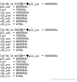
📙超频300MHz运行
- ✨ ⚡✨👉注意超频超过270HMz运行需要对内核进行调压操作。
- 🌿RP2040内核调压操作,需要引入组件:
hardware_vreg,在项目cmakelist.txt文件中添加:
# Add the standard library to the build
target_link_libraries(RP2040_CLOCK
        pico_stdlib
        hardware_clocks
        hardware_vreg)
- 🌿在调用调压参数文件中包含
#include "hardware/vreg.h"
- 内核默认电压为
1.1V,调压范围:(见Pico SDK v1.5.1\pico-sdk\src\rp2_common\hardware_vreg\include\hardware\vreg.h文件)
/** Possible voltage values that can be applied to the regulator
 */
enum vreg_voltage {
    VREG_VOLTAGE_0_85 = 0b0110,    ///< 0.85v
    VREG_VOLTAGE_0_90 = 0b0111,    ///< 0.90v
    VREG_VOLTAGE_0_95 = 0b1000,    ///< 0.95v
    VREG_VOLTAGE_1_00 = 0b1001,    ///< 1.00v
    VREG_VOLTAGE_1_05 = 0b1010,    ///< 1.05v
    VREG_VOLTAGE_1_10 = 0b1011,    ///< 1.10v
    VREG_VOLTAGE_1_15 = 0b1100,    ///< 1.15v
    VREG_VOLTAGE_1_20 = 0b1101,    ///< 1.20v
    VREG_VOLTAGE_1_25 = 0b1110,    ///< 1.25v
    VREG_VOLTAGE_1_30 = 0b1111,    ///< 1.30v

    VREG_VOLTAGE_MIN = VREG_VOLTAGE_0_85,      ///< Always the minimum possible voltage
    VREG_VOLTAGE_DEFAULT = VREG_VOLTAGE_1_10,  ///< Default voltage on power up.
    VREG_VOLTAGE_MAX = VREG_VOLTAGE_1_30,      ///< Always the maximum possible voltage
};
- 📄测试代码:
// This code is used to test the clocks of the RP2040 chip.
/*
时钟倍频参数计算:"\Pico SDK v1.5.1\pico-sdk\src\rp2_common\hardware_clocks\scripts\vcocalc.py"
计算方法:vcocalc.py 133

  CMSIS-DAP烧录命令:openocd -f interface/cmsis-dap.cfg -f target/rp2040.cfg -c  "adapter speed 5000"-c "program RP2040_CLOCK.elf verify reset exit"

 jlink命令: openocd -f interface/jlink.cfg -f target/rp2040.cfg  -c  "adapter speed 2000" -c  "program RP2040_RTC.elf verify reset exit"


 */
#include <stdio.h>
#include "pico/stdlib.h"
#include "hardware/gpio.h"
#include "hardware/divider.h"
#include "hardware/clocks.h"
#include "hardware/pll.h"
#include "hardware/clocks.h"
#include "hardware/vreg.h"
#include "hardware/structs/pll.h"
#include "hardware/structs/clocks.h"

#define BUILTIN_LED PICO_DEFAULT_LED_PIN // LED is on the same pin as the default LED 25

//频率参数
#define PLL_SYS_KHZ (300 * 1000)

// Measure the frequency of the given clock source
void measure_freqs(void)
{
    uint f_pll_sys = frequency_count_khz(CLOCKS_FC0_SRC_VALUE_PLL_SYS_CLKSRC_PRIMARY);
    uint f_pll_usb = frequency_count_khz(CLOCKS_FC0_SRC_VALUE_PLL_USB_CLKSRC_PRIMARY);
    uint f_rosc = frequency_count_khz(CLOCKS_FC0_SRC_VALUE_ROSC_CLKSRC);
    uint f_clk_sys = frequency_count_khz(CLOCKS_FC0_SRC_VALUE_CLK_SYS);
    uint f_clk_peri = frequency_count_khz(CLOCKS_FC0_SRC_VALUE_CLK_PERI);
    uint f_clk_usb = frequency_count_khz(CLOCKS_FC0_SRC_VALUE_CLK_USB);
    uint f_clk_adc = frequency_count_khz(CLOCKS_FC0_SRC_VALUE_CLK_ADC);
    uint f_clk_rtc = frequency_count_khz(CLOCKS_FC0_SRC_VALUE_CLK_RTC);

    printf("pll_sys  = %dkHz\n", f_pll_sys);
    printf("pll_usb  = %dkHz\n", f_pll_usb);
    printf("rosc     = %dkHz\n", f_rosc);
    printf("clk_sys  = %dkHz\n", f_clk_sys);
    printf("clk_peri = %dkHz\n", f_clk_peri);
    printf("clk_usb  = %dkHz\n", f_clk_usb);
    printf("clk_adc  = %dkHz\n", f_clk_adc);
    printf("clk_rtc  = %dkHz\n", f_clk_rtc);

    // Can't measure clk_ref / xosc as it is the ref
}

int main()
{

    vreg_set_voltage(VREG_VOLTAGE_1_30); // 300MHz需要调压,如果270MHz不需要加这句
    set_sys_clock_khz(PLL_SYS_KHZ, true);

    stdio_init_all();
    sleep_ms(3500);
    printf("RP204 Clock Test\n");
    measure_freqs();


    // GPIO initialisation.
    // We will make this GPIO an input, and pull it up by default
    gpio_init(BUILTIN_LED);
    gpio_set_dir(BUILTIN_LED, 1);
    gpio_pull_up(BUILTIN_LED);
    gpio_init(8);
    gpio_set_dir(8, GPIO_OUT);
    gpio_put(8, 0);
    while (true)
    {

        sleep_ms(1000);
        gpio_xor_mask(1ul << BUILTIN_LED); // Toggle the LED
        gpio_put(8, 1);                    // Turn on the LED
        sleep_ms(1000);
        gpio_put(8, 0); // Turn off the LED
        measure_freqs();
        __asm volatile("nop\n");
    }

    return 0;
}


 3891
3891

 被折叠的 条评论
为什么被折叠?
被折叠的 条评论
为什么被折叠?
 到【灌水乐园】发言


