


Introduction and System Architecture
We must first begin with a brief introduction to the hardware platform. Skip this if you have read the awsome material available on the web about the Intel architecture, I’ll try to briefly summarize it here.
The Intel platform is based on one or two chips. Small systems have one, the desktop and server ones are separated to a CPU complex and a PCH complex (PCH = Platform Controller Hub).
The CPU complex deals with computation. It holds the “processor” cores, e.g. Sunny Cove that implement the ISA, as well as cross core caches like the L3 cache, and more controllers that are grouped together as “the system agent” or the “uncore”. The uncore contains the memory controller and display, e.g. GPU and display controller.
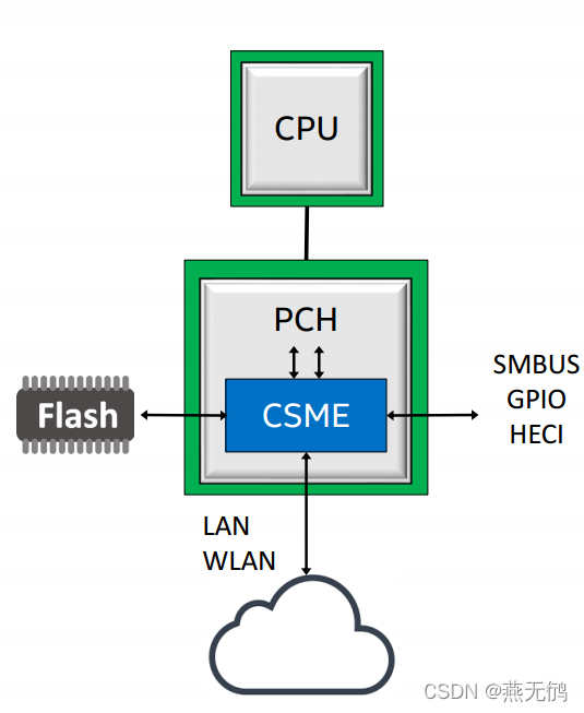
The PCH handles all other IO, including access to the firmware through SPI or eSPI, wifi, LAN, USB, HD audio, SMBus, thunderbolt and etc’. The PCH also hosts several embedded processors, like the PMC, the Power Management Controller
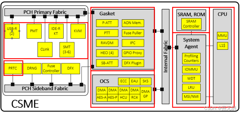
An additional part of the PCH is a very important player in our story, the CSME, or Converged Security & Management Engine, a i486 IP block (also called Minute IA). CSME is responsibly for much of the security model of Intel processors as well as many of the manageability features of the platform. The CSME block has its own dedicated ~1.5mb of SRAM memory and 128KB of ROM, as well as a dedicated IOMMU, called the A-Unit (that even has its own acode microcode) located in the CSME’s uncore’, thats allows access from ME to the main memory, as well as DMA to/from the main memory and using the main memory as an encrypted paging area (“virtual memory”). The CSME engine runs a customized version of the Minix3 microkernel, also recent versions have changed it beyond recognition adding many security features.
Buses
Lets use this post to also introduce the main interconnects in the system. The main externally facing interconnect bus is PCI-E, a fast bust that can reach 64GBps in its latest incarnations. A second external bus is the LPC, or Low Pin Count bus, a slow bus for connecting devices such as SPI flash, the TPM (explained below), and old peripherals such as PS/2 touchpads
Internally the platform is based around the IOSF, or Intel On-chip System Fabric, which is a pumped up version of PCI-E that supports many additional security and addressing features. For addressing IOSF adds SourceID and DestID fields that contain the source and destination of any IOSF transaction, extending PCI-E Bus-Device-Function (BDF) addressing to enable routing over bridges. IOSF also extends addressing by adding support for multiple address root namespaces, currently defining three: RS0 for host memory space, RS1 for CSME memory space, and RS2 for the Innovation-Engine (IE), another embedded controller currently present only on server chipsets. There are two IOSF busses in the PCH - the Primary Fabric and the Sideband Fabric. The Primary Fabric is high speed, connecting the CPU to the PCH (through a protocol call DMI), as well as high speed devices such as Gigbait Ethernet, WiFi and eSPI. The Sideband Fabric is used to connect the CSME to low-speed devices, including the PMC (Power Management Controller), the RNG generator, GPIO pins, USB, SMBus, and even debugging interfaces such as JTAG.
More Components
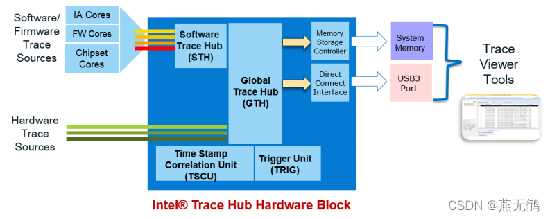
Another interesting component is the ITH, or Intel Trace Hub, which is codenamed North Peak (NPK). The ITH can trace different internal hardware component (VIA - Visualization of Internal Signals, ODLA - On-chip logic analyzer, SoCHAP - SOC performance counters, IPT - Intel Process Trace, AET - Intel Architecture Trace), and external component like CSME, the UEFI firmware, and you can even connect it to ETW. This telemetry eventually finds its way to Intel in various methods
The TPM is designed to provide a tamper proof environment to enforce system security through hardware. It implements in hardware many essential functions: sha1 & sha256 hashing algorithms, many crypto and key derivation functions, measurment registers call the Platform Configuration Registers (PCRs), a secret key - Endorsment Key - used to derive all other keys, and non-volatile storage slots for storing keys and hashes. Discrete TPM chips (i.e. those that are a separate chip on the mainboard or SOC and connected through the LPC) are call dTPMs, or can be implemented in the CSME module’s firmware and called fTPMs.
The TPM’s PCR are initialized to zero when the platform boots and are filled up with measurements through the boot process. PCRs 0-15 are intended for “static” use - they reset when the platform boots; They are supposed to give the OS loader a view of the platform initialization state. PCRs 17-22 are for “dynamic” use - they get reset on each secure launch (GETSEC[SENTER]); They are supposed to be used by the attestation sofware that checks if the OS is trusted.
The Flash Chip
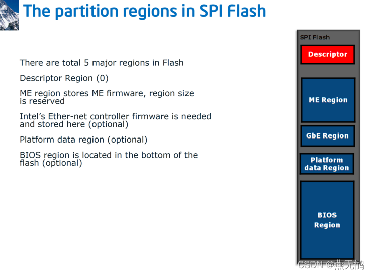
SPI flash has 5 major regions: the Descriptor regions, the CSME region, the Gigabit Ethernet Region, the Platform Data Region, and the UEFI region. In the image below you can see an example of how the flash is organized.

Later versions added more regions:
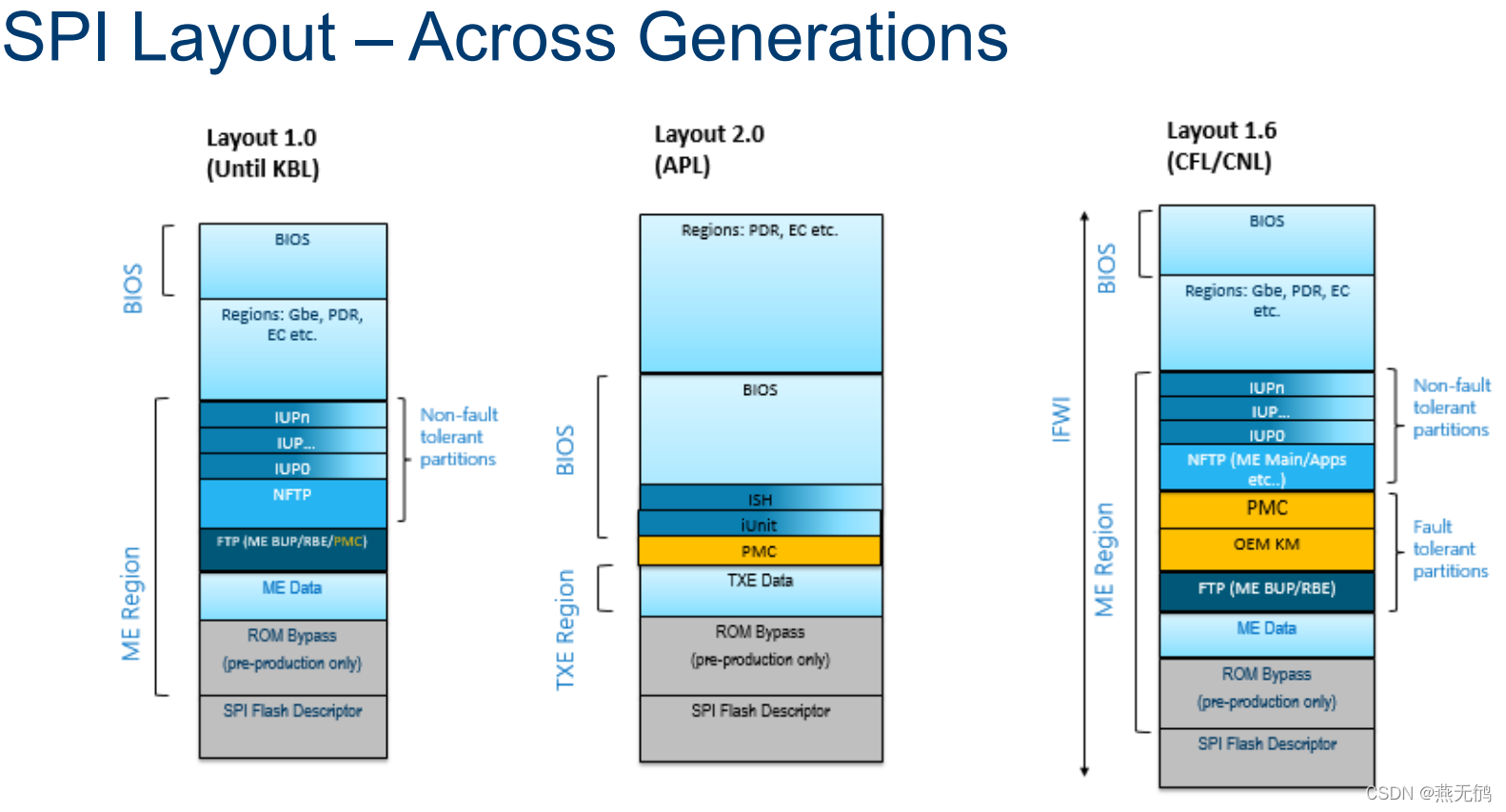
These regions are categorized as fault tolerant (FTPs) and non fault tolerant partitions (NFTPs). Fault tolerant partitions are critical for boot, and verified during early boot (like the RBE, the CSME ROM Boot extensions will discuss in a few paragraphs). If verification fails - the system does not boot. Examples of non fault tolerant partitions are the Integrated Sensor Hub (or ISH) firmware.
SPI flash protection is applied at multiple levels: On the flash chip itself, in the SPI flash controller (in the PCH), in UEFI code and in CSME code.
The SPI controller maps the entire flash to memory at a fixed address, so reads/writes are usually done simply by reading/writing memory. The SPI controller translates this to flash-specific commands issued on the SPI bus, using a table of flash-specific commands stored in the flash descriptor region. This is called “Hardware Sequencing”, meaning the SPI controller issues the actual SPI commands When hardware sequencing is in use, the SPI controller enforces several flash protections based on the masters region table in the flash (but can be overriden using a hardware PIN).
The SPI controller also implements a FLOCKDN flag. FLOCKDN is a write-once bit that, when set, disables use of software sequencing and modification of the PR registers until the next reset. The CSME sets this in the Bring-UP process (bup_storage_lock_spi_configuration(), see below). This happens when the UEFI notifies it that it is at the end of POST. In addition to the region access control table, the SPI controller also has an option to globally protect up to five regions in the flash from write access by the host using five registers, called Protected Registers (PRs), which are intended for the UEFI firmware to protect itself from modification while the OS is running.
It is also possible to issue direct flash commands using “Software Sequencing” by writing to the OPTYPE/OPMENU registers, since this can be used circumvent the SPI-enforced protections, software sequencing is usually disabled after POST using the FLOCKDN bit.
How is the flash updated?
UEFI region is updated through an UEFI capsule, This update happens during POST, before PRs and FLOCKDN is set, therefore, the BIOS region is still accessible to UEFI code.
Many OEMS have then own UEFI anti-tamper protections. For example, HP has SureStart on laptops and workstations, and Dell has TrustedDevice SafeBIOS. SafeBIOS copies bad firmware images to the EFI system partition, and the Dell Trusted Device software on Windows sends their hashes plus the hash of the UEFI firmware currently in memory to a Dell cloud server (*.delltrusteddevicesecurity.com) to check against a list of “authorized” hashes. Server platforms have similiar protections, including iLO for HP and iDRAC in Dell. The CSME region can usually be updated only from within the CSME. However, for more complicated upgrades CSME can temporarily unlock the ME region for host read & write
Overview
In the next sections we’ll look over all the stages of boot.
Early power on
Boot starts the PMC, the Power Management Controller. In modern Intel systems the PMC is an ARC core and its the first controller to execute code once electricity is applied to the system. We’ll talk more about PMC in a later post as its quiet interesting and has its own microcode and firmware, and event generates telemetry over the IOSF SB bus (which we’ll talk about in a moment).
While the PMC does its init, the rest of the system is held at bay at a RESET state.
The next part to start running is the CSME. Recall from the first post in the series, CSME, or Converged Security and Managment Engine is a MinuteIA (i486 CPU IP block) embedded in the Platform Controller Hub (PCH). The CSME begins running from its own embedded 128KB ROM - the CSME-ROM. This ROM is protected with a hardware fuse that is burned by Intel during production. When started the CSME ROM starts like a regular 486 processor BIOS - in the reset vector in real mode. Its first order of business is to enable protected mode. Next it checks if the system is configured in ROM bypass mode to assist debugging, if so maps the ROMB partition in SPI and starts executing from there - a mode call ROM bypass mode which we might dig into later. Next the CSME’s SRAM is initialized and a page table is created mapping SRAM and ROM and then paging is enabled. Once basic initialization is out of the way CSME can switch to C code that does some more complex initialization: initiating the IOMMU (AUnit), the IACP and hardware crypto keys which are calculated from fixed values in hardware. Finally, the DMA engine is used to read the next stage, called the Rom Boot Extension, or RBE, from the system firmware flash through SPI, and verifies it against the cryptographic keys prepared earlier. CSME ROM uses a special table, the Firmware Interface Table, or FIT, a table of pointers to specific regions in the flash and is itself stored in a fixed flash address.
The RBE’s job is to load the CSME OS kernel and verify it cryptographically. This process is optimized by using a mechanism called ICV, or Integrity-Check Values, hardware cached verified hashes - as long as the CSME kernel has the same hash it does not require crypto verification. Another check performed by the RBE is an anti-rollback check, making sure that once the CSME has been upgraded to a new version it cannot be downgraded back to the original version. Before starting the main CSME kernel the RBE loads pre-OS modules. An example pre-OS module is IDLM, which can be used to load debug-signed firmware on a production platform.
The kernel starts by enabling several platform security features: SMEP, Supervisor Mode Access Prevention, prevents exploits from running mapped kernel memory from ring3, and DEP, Data Execution Prevention, which prevents exploits from running code from stack regions. It also generates per-process syscall table permissions, aswell as ACL and IPC permissions.
Bring-Up (BUP)
Once everything is ready the kernel loads the Process Manager which executed “IBL processes”, which includes Bring-Up (BUP) and the Loader. The BUP loads virtual file system, or VFS server, parses the init script of the FTPR partition and loads all IBL modules listed there. This includes: the Event Dispatcher Server (eventdisp) - service that allows publishing, registering and acknowledging receipt of named events (sort of DBUS), the Bus Driver (busdrv) - a driver that permits other drivers to access devices on the CSME’s internal bus, the RTC driver (prtc), the Crypto/DMA driver (crypto) - provices access to services offered by the OCS hardware (SKS, DMA engines), the Storage driver (storage) - which provides access to the MFS filesystem, the Fuse driver (fpf) and finally the Loader Server (loadmgr).
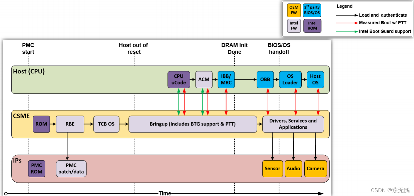
As seen in the image below, this is the stage where the CPU finally begins execution.
CPU initialization
Once the CSME is ready it releases the main CPU from the RESET state. The main CPU loads microcode from the FIT table and sets it up (after CSME verified the uCode cryptographically) . I won’t go into details about microcode, also called uCode, here as I have a full post planned on microcode later. Whats important to know is that microcode does not only include the “implementation” of the instruction set architecture (ISA), but also many routines for intilization, reset, paging, MSRs and much mich more. As part of CPU initialization it loads another module from the FIT, the Authenticated Code Module (ACM). The ACM implements BootGuard, a security feature to check cryptographically verify the UEFI signature before it is loaded (once called “AnchorCove”). This begins the Static Root Of Trust Model (SRTM), where CSME ROM verifies the CSME, which verifies the microcode, which verifies the ACM, which verifies the UEFI firmware, which verifies the operating system. This is done by chaining their hashes and storing them in the TPM. The ACM also initializes TXT, the Dynamic Root of Trust Model (DRTM) which we will detail in a few paragraphs.
UEFI initialization
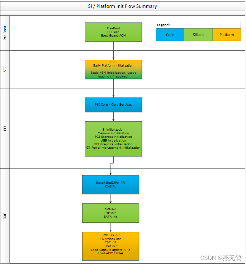
Once the CPU completes initialization, the Initial Boot Block (IBB) of the UEFI firmware is executed. The startup ACM authenticates parts of the FIT and the IBB using the OEM key burned into the fuses, authenticates it and measures it into PCR0 in the TPM. PCR0 is also referred to as the CRTM (Core Root of Trust Measurement)
The first stage of IBB is SEC which is responsible for very early platform initialisation, and loading the UEFI secure boot databases from non-volatile (NV) storage (these keys have various names such as PK, KEK, DB, DBX). Next comes PEI core, or “main” module of the Pre EFI initialization. It loads several modules (PEIMs) that initialiaze basic hardware such as memory, PCI-E, USB, basic graphics, basic power managment and more. Some of this code is implemented by the UEFI vendors or OEMs, and some come from Intel in “FSPs”, Firmware Support Packages, which perform “Silicon Initialization”. Common UEFI firmwears can have as many as a 100 PIE modules.
The UEFI spec does not covers signature/authentication checks in PEI phases. Thats why Intel needed BootGuard to do the bootstrapping: At power-on, BootGuard measures the IBB ranges which include PEI.
Following PEI the Driver Execution Environment is loaded by a security PEI module which verifies their integrity cryptographically beforehand. DXE is responsible for setting up all the rest of the hardware and software execution environment in preparation for OS loading. It also setups System Management Mode (which we’ll talk about soon), sensors and monitoring, boot services, real-time clocks and more. A modern UEFI firmware can have as much as 200 different DXE drivers installed.
Many OEMs use BootGuard to authenticate DXE as well by configuring the IBBs to include the entire PEI volume in the flash (PEI Core + PEI modules) and the DXE Core. Secure Boot is used to verify each PEI/DXE image that is loaded before executing it. These images are measured and extended into the TPM’s PCR0 as well.
The DXE environment initializes two important tables: the EFI Runtime services table and the EFI Boot Service Table. Boot Services are used by the operating system only during boot and discarded thereafter. These include memory allocation services and services to access DXE drivers like storage, networking and display. Runtime services are kept in memory for use by the operating system whenever required, and include routines for getting and setting the value of EFI variables, clock manipulation, hardware configuration, firmware capsule updates and more
Finally the UEFI firmware measures the platform (e.g. chipset) security configuration (NV variables) into PCR1 and then locks them by calling a function in the ACM.


 473
473


 被折叠的 条评论
为什么被折叠?
被折叠的 条评论
为什么被折叠?
 到【灌水乐园】发言


