


9 - 状态机代码设计与仿真
串口数据发送

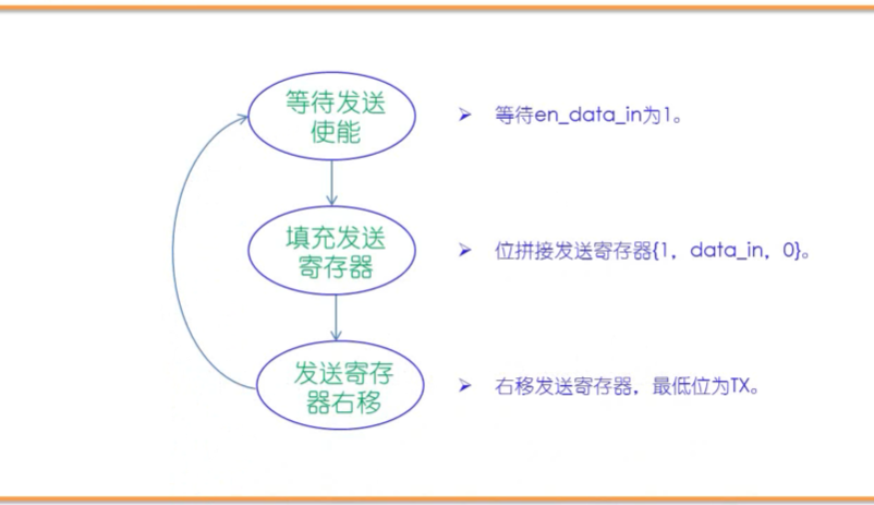
状态规划:
代码:
//2021.11.23 lyw
//Serial port data sending

`timescale 1ns/10ps

module UART_TXer (
                clk,
                res,
                data_in,
                en_data_in,
                TX,
                rdy
);

input           clk;
input           res;
input[7:0]      data_in;    //data ready to send
input           en_data_in;     //enable to send
output          TX;
output          rdy;    //free flag: 0 means free

reg [3:0]       state;  //main state machine
reg [9:0]       send_buf;   //sending register
assign          TX=send_buf[0];     //connect TX

reg [12:0]      con;    //Calculating Porter period
reg [9:0]       send_flag;  //right shift is over
reg             rdy;    //ready,also busy

always @(posedge clk or negedge res) begin
    if(~res) begin
        state<=0; send_buf<=1;con<=0;rdy<=0;
        send_flag<=10'b10_0000_0000;
    end
    else begin
        case(state)
        0://wait enable signal
        begin
            if (en_data_in) begin
                send_buf={1'b1,data_in,1'b0};
                send_flag<=10'b10_0000_0000;
                rdy<=1;
                state<=1;
            end
        end
        1://Serial port send, right shift register
        begin
            if (con==5000-1) begin
                con<=0;
            end
            else begin
                con<=con+1;
            end

            if (con==5000-1) begin
                send_buf[8:0]=send_buf[9:1];
                send_flag[8:0]=send_flag[9:1];
            end
            if (send_flag[0]) begin
                state<=0;
                rdy<=0;
            end

        end
        endcase
end

end
endmodule


//-----testbench of UART_TXer-----
module UART_TXer_tb;

reg             clk,res;
reg [7:0]       data_in;
reg             en_data_in;
wire            TX;
wire            rdy;

UART_TXer UART_TXer (
                clk,
                res,
                data_in,
                en_data_in,
                TX,
                rdy
);

initial begin
                clk<=0;res<=0;data_in<=8'h0a;en_data_in<=0;
    #17             res<=1;
    #30             en_data_in<=1;
    #400000         en_data_in<=0;

    #150000         $stop;
end

always #5 clk<=~clk;

endmodule
仿真波形:

en_data_in 为 1 时,使能发送,下一周期立马开始发送,同时忙信号为 1。
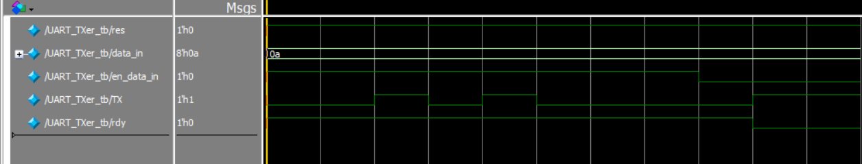
开始发送后,缓冲寄存器为{1,data,0},以 0 开始,发送 data 后,以 1 结束。
data 是 8’h0a 即 8’b00001010,右移发送,发送顺序是 01010000。
发送 data 结束后,TX=1,同时忙信号为 0。
如果改成发送的 data 为:8‘h7f

可以清楚看到 0_1111_1110_1
如果 data 为:8’h55
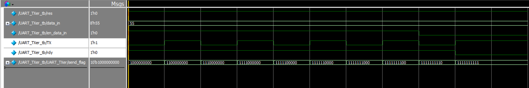
也可以看到 0_1010_1010_1


 350
350


 被折叠的 条评论
为什么被折叠?
被折叠的 条评论
为什么被折叠?
 到【灌水乐园】发言


