


一、问题分析
针对机械臂码垛摆放的问题,大致就两种情况:托盘摆正情况和带有旋转情况。
因为托盘水平放置,所以目前不考虑水平倾斜情况。
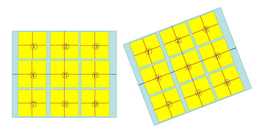
图示以3x3摆放为例
针对摆正的情况,机械臂码垛很方便:
- 相机识别检测托盘中心位置(pallet_centerX,pallet_centerY)。
- 根据摆放箱子之间的间隔位置变量,计算①号箱子的空间位置,然后做个循环生成①到⑨箱子的空间位置。
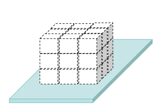
- 根据摆放的层数变量,生成多层摆放的空间位置。
当实际待放置的目标托盘带有旋转的情况时,理论上也比较简单:
- 根据托盘中心位置依次求出个托盘摆正情况下的应该摆放位置的中心点坐标。
- 计算托盘的旋转角度 θ \theta θ。
- 根据摆放中心点位置坐标计算旋转后的中心点坐标。
- 生成实际摆放的6Dofs ( x , y , z , 0 , 0 , θ ) (x,y,z,0,0,\theta) (x,y,z,0,0,θ)
二、托盘倾斜角度的计算
-
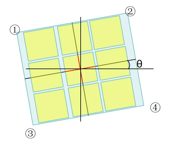
(先从图片的二维平面层面考虑)首先检测识别托盘的位置并计算托盘四个顶点的位置(x,y)。
这部分就是先图像检测的方法检测出角点位置,然后根据x和y位置区分得到四个点。
-
根据①②点和①③点计算二范数判断长短边。
d ( x , y ) = ∥ x − y ∥ 2 d(x,y) = \begin{Vmatrix} x-y \end{Vmatrix}^2 d(x,y)= x−y 2
float calculatePointDistance(const point point1, const point point2) { return sqrt(pow(point1.x - point2.x, 2) + pow(point1.y - point2.y, 2)); } -
长短边区分出来之后,计算长边与水平直线的角度。
θ = a r c t a n ( y 1 − y 2 x 1 − x 2 ) \theta = arctan(\frac{y1-y2}{x1-x2} ) θ=arctan(x1−x2y1−y2)
float calculateVectorAngle(const point& p1, const point& p2) { float dx = p2.x - p1.x; float dy = p2.y - p1.y; float angle = atan2(dy, dx); return angle; } -
根据四个点计算中心点坐标。
( x 1 + x 2 + x 3 + x 4 4 , y 1 + y 2 + y 3 + y 4 4 ) (\frac{x1+x2+x3+x4}{4} , \frac{y1+y2+y3+y4}{4} ) (4x1+x2+x3+x4,4y1+y2+y3+y4)
point calculateCenter(const point points[], int numPoints)
{
	float sumX = 0.0f;
	float sumY = 0.0f;

	for (int i = 0; i < numPoints; ++i)
	{
		sumX += points[i].x;
		sumY += points[i].y;
	}

	return { sumX / numPoints, sumY / numPoints };
}
三、旋转后各点位置的计算
3.1 标准坐标系情况
首先讨论一下点绕点的旋转,先以标准坐标系为例进行考虑。
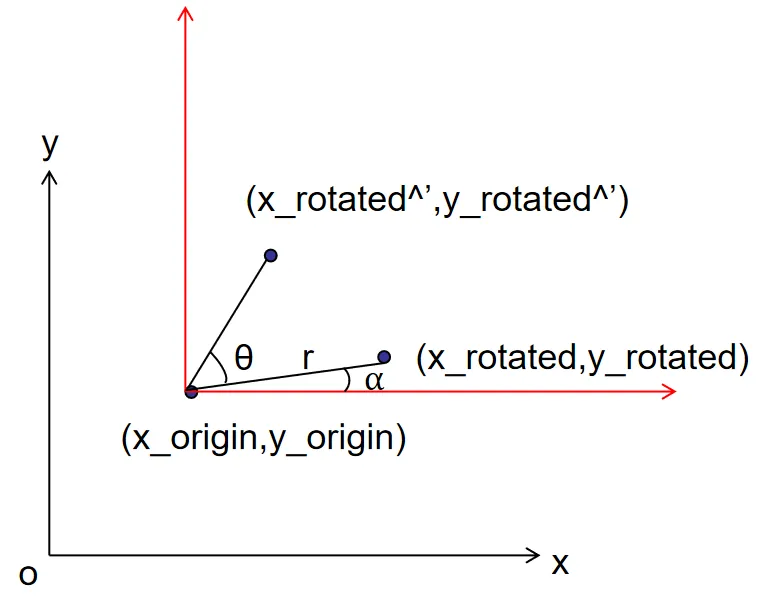
将实际每个托盘的中心点位置绕托盘中心旋转的问题简化为如图所示。
如图就是计算 ( x r o t a t e d , y r o t a t e d ) (x_{rotated}, y_{rotated}) (xrotated,yrotated)绕 ( x o r i g i n , y o r i g i n ) (x_{origin},y_{origin}) (xorigin,yorigin)旋转 θ \theta θ度之后的点 ( x r o t a t e d ’ , y r o t a t e d ’ ) (x_{rotated}^’,y_{rotated}^’) (xrotated’,yrotated’)的位置。
-
为了计算方便,将这个坐标系移动,相当于以 ( x r o t a t e d , y r o t a t e d ) (x_{rotated}, y_{rotated}) (xrotated,yrotated)为原点。
{ d x = x r o t a t e d − x o r i g i n d y = y r o t a t e d − y o r i g i n \left\{\begin{matrix} dx = x_{rotated} - x_{origin} \\ dy = y_{rotated} - y_{origin} \end{matrix}\right. {dx=xrotated−xorigindy=yrotated−yorigin
-
为了讨论方便,从极坐标角度推算比较方便理解。
( x r o t a t e d , y r o t a t e d ) (x_{rotated}, y_{rotated}) (xrotated,yrotated)也可以表示为 ( r c o s ( α ) , r s i n ( α ) ) (rcos(\alpha), rsin(\alpha)) (rcos(α),rsin(α)),即
{ d x = r c o s ( α ) d y = r s i n ( α ) \left\{\begin{matrix} dx = rcos(\alpha ) \\ dy = rsin(\alpha) \end{matrix}\right. {dx=rcos(α)dy=rsin(α)
-
当旋转 θ \theta θ度之后,旋转后的点表示为 ( r c o s ( α + θ ) , r s i n ( α + θ ) ) (rcos(\alpha + \theta), rsin(\alpha + \theta)) (rcos(α+θ),rsin(α+θ))
将三角函数展开 ( r c o s ( α ) c o s ( θ ) − r s i n ( α ) s i n ( θ ) , r c o s ( α ) s i n ( θ ) + r s i n ( α ) c o s ( θ ) ) (rcos(\alpha)cos(\theta) - rsin(\alpha)sin(\theta), rcos(\alpha)sin(\theta) + rsin(\alpha)cos(\theta)) (rcos(α)cos(θ)−rsin(α)sin(θ),rcos(α)sin(θ)+rsin(α)cos(θ))
也就是 ( d x c o s ( θ ) − d y s i n ( θ ) , d x s i n ( θ ) , d y c o s ( θ ) ) (dxcos(\theta) - dysin(\theta), dxsin(\theta), dycos(\theta)) (dxcos(θ)−dysin(θ),dxsin(θ),dycos(θ))
-
最后再将坐标系转换回去,所以最后就是
{ x r o t a t e d ′ = ( x r o t a t e d − x o r i g i n ) c o s ( θ ) − ( y r o t a t e d − y o r i g i n ) s i n ( θ ) + x o r i g i n y r o t a t e d ′ = ( y r o t a t e d − y o r i g i n ) s i n ( θ ) − ( y r o t a t e d − y o r i g i n ) c o s ( θ ) + y o r i g i n \left\{\begin{matrix} x_{rotated}^{'} = (x_{rotated}- x_{origin})cos(\theta) - (y_{rotated}-y_{origin})sin(\theta) + x_{origin} \\ y_{rotated}^{'} = (y_{rotated}- y_{origin})sin(\theta) - (y_{rotated}-y_{origin})cos(\theta) + y_{origin} \end{matrix}\right. {xrotated′=(xrotated−xorigin)cos(θ)−(yrotated−yorigin)sin(θ)+xoriginyrotated′=(yrotated−yorigin)sin(θ)−(yrotated−yorigin)cos(θ)+yorigin
-
用矩阵形式表示就是
[ x r o t a t e d ′ y r o t a t e d ′ ] = [ c o s ( θ ) − s i n ( θ ) s i n ( θ ) c o s ( θ ) ] [ x r o t a t e d − x o r i g i n y r o t a t e d − y o r i g i n ] + [ x o r i g i n y o r i g i n ] \begin{bmatrix} x_{rotated}^{'} \\ y_{rotated}^{'} \end{bmatrix} = \begin{bmatrix} cos(\theta) & -sin(\theta)\\ sin(\theta) & cos(\theta) \end{bmatrix} \begin{bmatrix} x_{rotated} -x_{origin}\\ y_{rotated} - y_{origin} \end{bmatrix} + \begin{bmatrix} x_{origin} \\ y_{origin} \end{bmatrix} [xrotated′yrotated′]=[cos(θ)sin(θ)−sin(θ)cos(θ)][xrotated−xoriginyrotated−yorigin]+[xoriginyorigin]
3.2 机械臂基座坐标系情况
正常坐标系一般是左x上y,但是需要将点位坐标转换到机械臂坐标系用来码垛放置,而机械臂基座坐标系是前面为x左边为y,上面为z,所以实际空间角度从上面往下看就是左y上x这个样子。
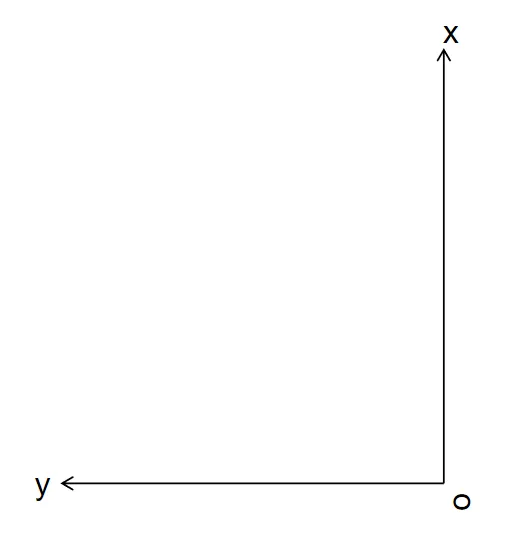
一开始以为点旋转是不是会不一样,但是这种情况按照上面的推算过程推算后,结果是一样的。
void PlaceStrategy::pointRotate(float& x_rotated, float& y_rotated,
     const float x_origin, const float y_origin, const float yaw)
{
    float dx = x_rotated - x_origin;
    float dy = y_rotated - y_origin;

    // 旋转后的新坐标
    float new_x = dx * std::cos(yaw) - dy * std::sin(yaw) + x_origin;
    float new_y = dx * std::sin(yaw) + dy * std::cos(yaw) + y_origin;

    // 更新结果
    x_rotated = new_x;
    y_rotated = new_y;
}
四、3x3箱子的中心点位置计算
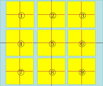
计算的策略就是先计算第一个箱子的中心点位置
( p a l l e t c e n t e r X − b o x L − i n t e r v a l , p a l l l e t c e n t e r Y − b o x W − i n t e r v a l ) (pallet_{centerX}-box_L - interval, palllet_{centerY} - box_W-interval) (palletcenterX−boxL−interval,pallletcenterY−boxW−interval)
然后计算旋转后的点
最后计算同一个托盘所有箱子中心点位置。
std::vector<locatingPlace> PlaceStrategy::get_3x3_BoxLocations(float pallet_centerX, float pallet_centerY,
float pallet_centerZ, float pallet_centerYaw)
{
box_location.clear();
box_location.resize(9 * m_num_layers);
m_pallet_centerX = pallet_centerX;
m_pallet_centerY = pallet_centerY;
m_pallet_centerZ = pallet_centerZ;
m_pallet_centerYaw = pallet_centerYaw;
for (int i = 0; i < box_location.size(); i++)
{
calculate_3x3_BoxPosition(i);
}
return box_location;
}
void PlaceStrategy::calculate_3x3_BoxPosition(int index)
{
int layer = index / 9;
int box_index = index % 9;
float first_x = m_pallet_centerX + m_box_W + m_interval;
float first_y = m_pallet_centerY + m_box_L + m_interval;
// 先计算旋转前的X,Y
float tempY = first_y - (box_index % 3) * (m_box_L + m_interval);
float tempX = first_x - (box_index / 3) * (m_box_W + m_interval);
// 计算旋转后的
pointRotate(tempX, tempY, m_pallet_centerX, m_pallet_centerY, m_pallet_centerYaw);
box_location[index].x = tempX;
box_location[index].y = tempY;
box_location[index].z = m_pallet_centerZ + m_box_H * layer;
box_location[index].roll = 0;
box_location[index].pitch = 0;
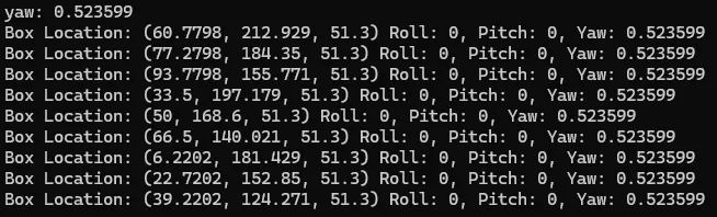
box_location[index].yaw = m_pallet_centerYaw;
}
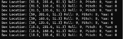
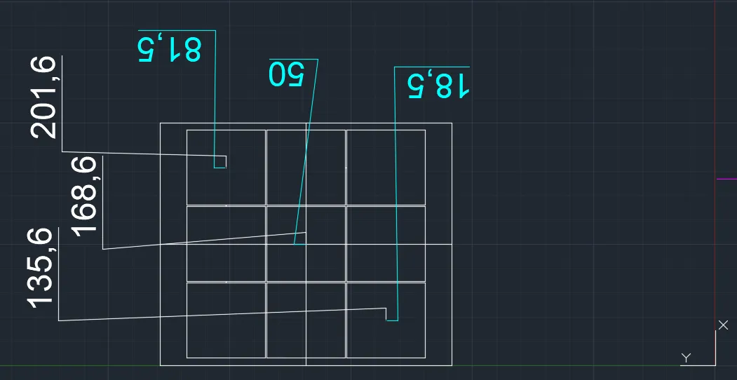
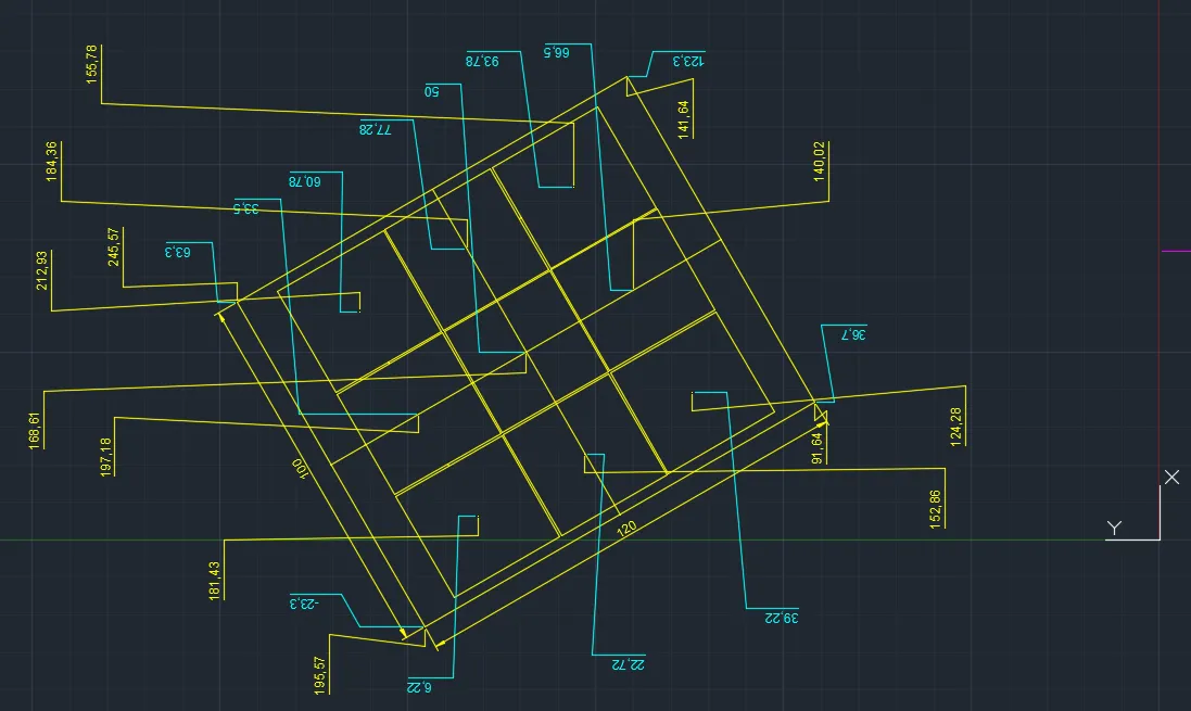
五、验证
使用CAD绘制了相关的验证场景,托盘120x100cm,箱子31x32.5x31.3cm
间隔0.5cm,假设检测到托盘高度20cm。
摆正情况下计算一层
倾斜情况下计算一层


 4364
4364

 被折叠的 条评论
为什么被折叠?
被折叠的 条评论
为什么被折叠?
 到【灌水乐园】发言


