


目录
前言:
ESP32的IDF配置方式与STM32库函数类似,由于有STM32的基础ESP32的文章将以代码实例为主,不再讲解理论知识。(更多教程还在持续学习更新中。。。。。。。。。)
API中对IO口的定义
typedef enum {
    GPIO_NUM_NC = -1,    /*!< Use to signal not connected to S/W */
    GPIO_NUM_0 = 0,     /*!< GPIO0, input and output */
    GPIO_NUM_1 = 1,     /*!< GPIO1, input and output */
    GPIO_NUM_2 = 2,     /*!< GPIO2, input and output */
    GPIO_NUM_3 = 3,     /*!< GPIO3, input and output */
    GPIO_NUM_4 = 4,     /*!< GPIO4, input and output */
    GPIO_NUM_5 = 5,     /*!< GPIO5, input and output */
    GPIO_NUM_6 = 6,     /*!< GPIO6, input and output */
    GPIO_NUM_7 = 7,     /*!< GPIO7, input and output */
    GPIO_NUM_8 = 8,     /*!< GPIO8, input and output */
    GPIO_NUM_9 = 9,     /*!< GPIO9, input and output */
    GPIO_NUM_10 = 10,   /*!< GPIO10, input and output */
    GPIO_NUM_11 = 11,   /*!< GPIO11, input and output */
    GPIO_NUM_12 = 12,   /*!< GPIO12, input and output */
    GPIO_NUM_13 = 13,   /*!< GPIO13, input and output */
    GPIO_NUM_14 = 14,   /*!< GPIO14, input and output */
    GPIO_NUM_15 = 15,   /*!< GPIO15, input and output */
    GPIO_NUM_16 = 16,   /*!< GPIO16, input and output */
    GPIO_NUM_17 = 17,   /*!< GPIO17, input and output */
    GPIO_NUM_18 = 18,   /*!< GPIO18, input and output */
    GPIO_NUM_19 = 19,   /*!< GPIO19, input and output */
    GPIO_NUM_20 = 20,   /*!< GPIO20, input and output */
    GPIO_NUM_21 = 21,   /*!< GPIO21, input and output */
    GPIO_NUM_26 = 26,   /*!< GPIO26, input and output */
    GPIO_NUM_27 = 27,   /*!< GPIO27, input and output */
    GPIO_NUM_28 = 28,   /*!< GPIO28, input and output */
    GPIO_NUM_29 = 29,   /*!< GPIO29, input and output */
    GPIO_NUM_30 = 30,   /*!< GPIO30, input and output */
    GPIO_NUM_31 = 31,   /*!< GPIO31, input and output */
    GPIO_NUM_32 = 32,   /*!< GPIO32, input and output */
    GPIO_NUM_33 = 33,   /*!< GPIO33, input and output */
    GPIO_NUM_34 = 34,   /*!< GPIO34, input and output */
    GPIO_NUM_35 = 35,   /*!< GPIO35, input and output */
    GPIO_NUM_36 = 36,   /*!< GPIO36, input and output */
    GPIO_NUM_37 = 37,   /*!< GPIO37, input and output */
    GPIO_NUM_38 = 38,   /*!< GPIO38, input and output */
    GPIO_NUM_39 = 39,   /*!< GPIO39, input and output */
    GPIO_NUM_40 = 40,   /*!< GPIO40, input and output */
    GPIO_NUM_41 = 41,   /*!< GPIO41, input and output */
    GPIO_NUM_42 = 42,   /*!< GPIO42, input and output */
    GPIO_NUM_43 = 43,   /*!< GPIO43, input and output */
    GPIO_NUM_44 = 44,   /*!< GPIO44, input and output */
    GPIO_NUM_45 = 45,   /*!< GPIO45, input and output */
    GPIO_NUM_46 = 46,   /*!< GPIO46, input and output */
    GPIO_NUM_47 = 47,   /*!< GPIO47, input and output */
    GPIO_NUM_48 = 48,   /*!< GPIO48, input and output */
    GPIO_NUM_MAX,
} gpio_num_t;
初始化函数
初始化函数与STM32的库函数配置方式类似,使用 gpio_config()函数进行初始化。
esp_err_t gpio_config(const gpio_config_t *pGPIOConfig)GPIO结构体指针
typedef struct {
    uint64_t pin_bit_mask;          /*!< GPIO pin: set with bit mask, each bit maps to a GPIO */
    gpio_mode_t mode;               /*!< GPIO mode: set input/output mode                     */
    gpio_pullup_t pull_up_en;       /*!< GPIO pull-up                                         */
    gpio_pulldown_t pull_down_en;   /*!< GPIO pull-down                                       */
    gpio_int_type_t intr_type;      /*!< GPIO interrupt type                                  */
#if SOC_GPIO_SUPPORT_PIN_HYS_FILTER
    gpio_hys_ctrl_mode_t hys_ctrl_mode;       /*!< GPIO hysteresis: hysteresis filter on slope input    */
#endif
} gpio_config_t;
关于各个参数的说明:
/*
*中断配置*.intr_type/ GPIO_INTR_DISABLE     /失能中断
                  / GPIO_INTR_POSEDGE     /上升沿
                  / GPIO_INTR_NEGEDGE     /下降沿
                  / GPIO_INTR_ANYEDGE     /上升沿和下降沿中断
                  / GPIO_INTR_LOW_LEVEL   /输入低电平触发
                  / GPIO_INTR_HIGH_LEVEL  /输入高电平触发
****************************************************************

*引脚模式*.mode      / GPIO_MODE_DISABLE            /失能输入输出模式
                   / GPIO_MODE_INPUT              /仅输入模式
                   / GPIO_MODE_OUTPUT             /仅输出模式
                   / GPIO_MODE_OUTPUT_OD          /输出开漏模式
                   / GPIO_MODE_INPUT_OUTPUT_OD    /输入输出开漏模式
                   / GPIO_MODE_INPUT_OUTPUT       /输入输出模式
****************************************************************

*配置上拉*.pull_up_en / GPIO_PULLUP_DISABLE   /失能上拉
                    / GPIO_PULLUP_ENABLE    /使能上拉
****************************************************************

*配置下拉*.pull_down_en / GPIO_PULLDOWN_DISABLE   /失能上拉
                       / GPIO_PULLDOWN_ENABLE      /使能上拉
****************************************************************

*引脚位  *.pin_bit_mask   / (1 << x)其中x为ESP32S3中可用GPIO  /设置的引脚位,比如本实验用到的IO1引脚,则写为: (1ull << GPIO_NUM_1)
****************************************************************

*其他*  /  GPIO_PULLUP_ONLY       /仅上拉
        /  GPIO_PULLDOWN_ONLY     /仅下拉
        /  GPIO_PULLUP_PULLDOWN   /上拉+下拉
        /  GPIO_FLOATING          /浮空

*/
实例
IO进行输出初始化函数实例:
void led_init(void)
{
    gpio_config_t gpio_init_struct = {0};      //声明结构体

    gpio_init_struct.intr_type = GPIO_INTR_DISABLE;         /* 失能引脚中断 */
    gpio_init_struct.mode = GPIO_MODE_INPUT_OUTPUT;         /* 输入输出模式 */
    gpio_init_struct.pull_up_en = GPIO_PULLUP_ENABLE;       /* 使能上拉 */
    gpio_init_struct.pull_down_en = GPIO_PULLDOWN_DISABLE;  /* 失能下拉 */
    gpio_init_struct.pin_bit_mask = 1ull << GPIO_NUM_1;   /* 设置的引脚的位掩码 */
    gpio_config(&gpio_init_struct);                         /* 配置GPIO */
}
IO进行输入初始化函数实例:
void key_init(void)
{
    gpio_config_t gpio_init_struct;

    gpio_init_struct.intr_type = GPIO_INTR_DISABLE;         /* 失能引脚中断 */
    gpio_init_struct.mode = GPIO_MODE_INPUT;                /* 输入模式 */
    gpio_init_struct.pull_up_en = GPIO_PULLUP_ENABLE;       /* 使能上拉 */
    gpio_init_struct.pull_down_en = GPIO_PULLDOWN_DISABLE;  /* 失能下拉 */
    gpio_init_struct.pin_bit_mask = 1ull << BOOT_GPIO_PIN;  /* BOOT按键引脚 */
    gpio_config(&gpio_init_struct);                         /* 配置使能 */
}
设置IO口输出电平:
原型函数:
esp_err_t gpio_set_level(gpio_num_t gpio_num, uint32_t level);

/*
gpio_num   /GPIO引脚号。(在gpio_types.h文件中枚举gpio_num_t有定义)
level      /GPIO引脚输出电平。0:低电平,1:高电平
*/
*****************************************************************
实例:
gpio_set_level(GPIO_NUM_1, 1) :
vTaskDelay(500);
gpio_set_level(GPIO_NUM_1, 0);
获取IO口当前电平:
原型函数:
esp_err_t gpio_get_level(gpio_num_t gpio_num);

/*
    gpio_num      /GPIO引脚号。(在gpio_types.h文件中枚举gpio_num_t有定义)

    返回值:ESP_OK表示获取成功,ESP_FAIL表示获取失败。
*/
******************************************************************
实例:

KEY=gpio_get_level(GPIO_NUM_1)
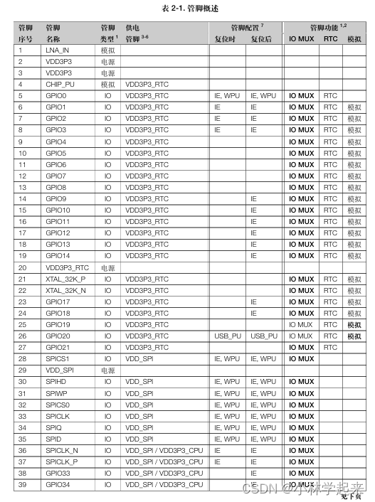
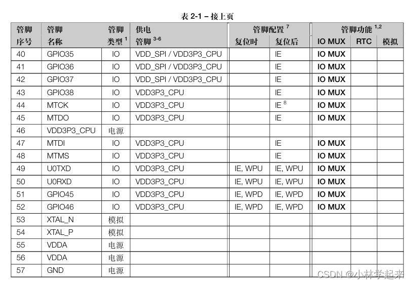
官方截图的引脚表格
IO口一览表:
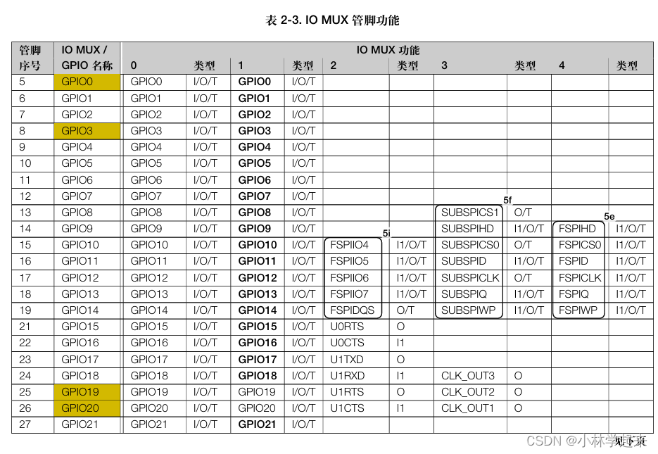
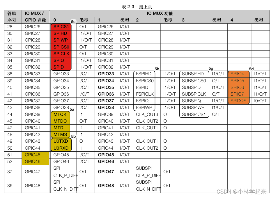
IO MUX管脚功能一览表(功能编程主要看这个):
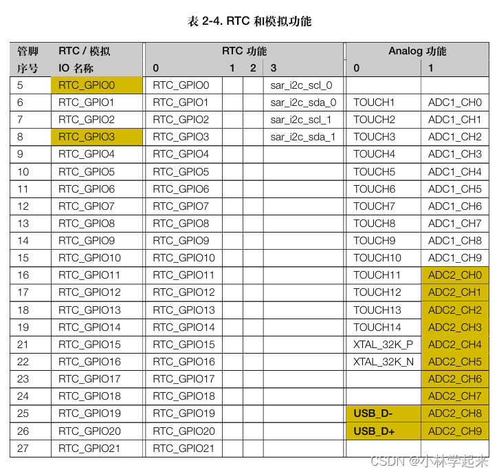
RTC和模拟功能IO口一览表(ADC与低功耗编程看这个):
 参考文件:
参考文件:


 1628
1628

 被折叠的 条评论
为什么被折叠?
被折叠的 条评论
为什么被折叠?
 到【灌水乐园】发言


