


目录
串口通信简介
参考文章(大佬写的很好可以去看一下)
arduino支持的串行通信有UART,I2C和SPI三种通信协议方式
根据串行数据的传输方向,我们可以将通信分为单工,半双工,双工
单工
是指数据传输仅能沿一个方向,不能实现反向传输
半双工
是指数据传输可以沿两个方向,但不能同时进行传输
全双工
是指数据可以同时进行双向传输
硬件串口通信(UART)——HardwareSerial 类库
除了常见的函数外,另外比较常用的
peek()
功能:返回1字节的数据,但不会从接受缓冲区删除数据,与read()函数不同,read()函数读取该函数后,会从接受缓冲区删除该数据。
write()
功能:输出数据到串口。以字节形式输出到串口,它与print()的区别在于:当使用print()发送一个数据时,arduino发送的并不是数据本身,而是将数据转换为字符,再将字符对应的ASCII码发送出去,串口监视器收到ASCII码,则会显示对应的字符,因此使用print()函数是以ASCII码形式输出数据到串口; 而当使用write() 函数时,arduino发送的是数值本身。但串口监视器接收到数据后,会将数值当做ASCII码而显示其对应的字符。
例如,当使用serial.write(INT)输出一个整型数 123 时,显示出的字符为"{",因为ASCII码 123 对应的字符为"{"
软件模拟串口通信——softwareserial 类库使用
除HardwareSerial 类库外,arduino还提供了softwareserial类库,可将其他数字引脚通过程序模拟成串口通信引脚
通常将arduino上自带的串口成为硬件串口,而使用softwareserial类库模拟成的串口称为软件模拟串口
sofawareserial类库成员函数
其中定义的成员函数和硬件串口的类似
available(), begin(), read(), write(), print(), println(), peek(),函数用法相同
此外软串口还有如下成员函数
SofaWareSerial()
功能:这是SoftwareSerial类的构造函数,通过它可以指定软串口的RX和TX引脚
语法:SoftwareSerial mySerial = SoftwareSerial(rxPin, txPin)
listen()
功能:开启软串口监听状态
arduino在同一时间仅能监听一个软串口,当需要监听某一串口时,需要对该对象调用此函数开启监听功能
overflow()
功能:检测缓冲区是否已经溢出。软串口缓冲区最多可保存64B的数据
实验
使用UART通信模式,需要两部分RX-TX, TX-RX的连接
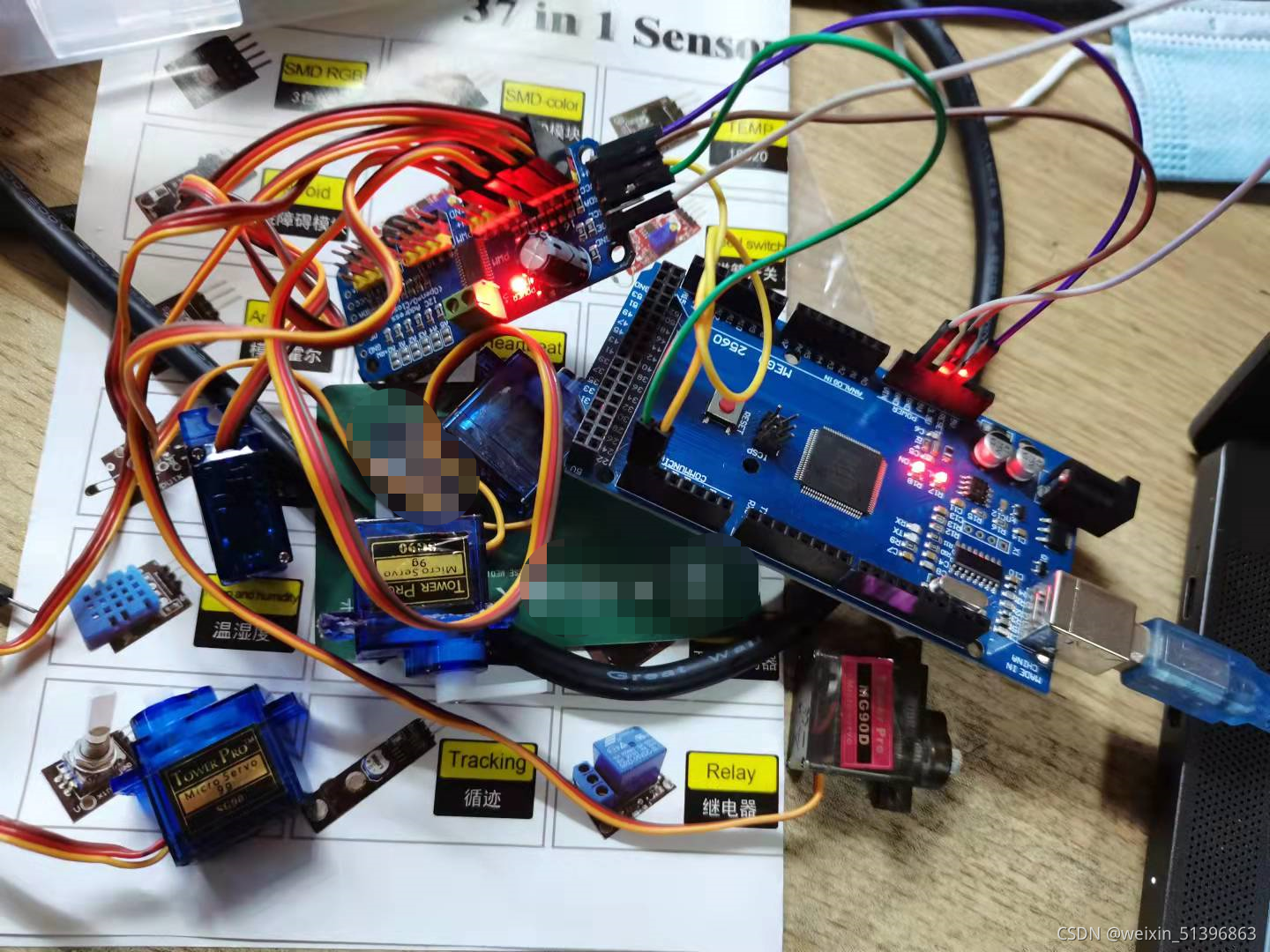
两个arduino实现通信,一个uno,一个mega,uno端连接lcd1602,显示通信类容
mega的程序如下:
String device_mega = "";
String device_uno = "";
void setup() {
  // put your setup code here, to run once:
  Serial.begin(9600);
  Serial1.begin(9600);
}

void loop() {
  // put your main code here, to run repeatedly:
  if(Serial.available()>0){
    if(Serial.peek() != '\n')
      device_mega += (char)Serial.read();
    else{
      Serial.read();
      Serial.print("you said: ");
      Serial.println(device_mega);
      Serial1.println(device_mega);
      device_mega = "";
    }
  }

  if(Serial1.available()>0){
    if(Serial.available()>0){
      if(Serial1.peek() != '\n')
        device_uno += (char)Serial1.read();
      else{
        Serial1.read();
        Serial.print("the uno said: ");
        Serial.println(device_uno);
        device_uno = "";
      }
    }
  }
}
uno的程序如下
#include "LiquidCrystal.h"
#include "SoftwareSerial.h"
SoftwareSerial myserial(10,11);
String device_mega = "";
String device_uno = "";
LiquidCrystal lcd(7, 6, 5, 4, 3, 2);
void setup() {
  // put your setup code here, to run once:
  Serial.begin(9600);
  myserial.begin(9600);
  myserial.listen();
  lcd.begin(16,2);
  lcd.clear();

}

void loop() {
  // put your main code here, to run repeatedly:
  if(softSerial.available()>0){
    delay(100);
    lcd.clear();
    while(Serial.available()>0)
      lcd.write(Serial.read());
    device_mega = "";
  }
  if(Serial.available()>0){
	if(softSerial.peek() != '\n')
		device_uno += (char)Serial.read();
	else
	{
	Serial.read();
	Serial.print("you said:");
	Serial.println(device_uno);
	device_uno = "";
	}
}
}

I2C协议
使用IIC协议可以通过两根双向的总线数据线SDA 和时钟线 SCL 使arduino 连接最多128个 IIC 从机设备。
与串口通信的一对一通信方式不同,总线通信通常有主机和从机之分。通信时,主机负责启动和终止数据传送,同时还要输出时钟信号;从机会被主机寻址,并且响应主机的通信请求;在IIC通信中,通信速率的控制有主机完成,主机会通过SCL引脚输出时钟信号供总线上的所有从机使用;同时,IIC是一种半双工通信方式
| 型号 | SDA | SCL |
|---|---|---|
| UNO | A4 | A5 |
| MEGA | 20 | 21 |
注意一定是A4,A5不是标有SDA 和 SCL 的引脚
arduino的强大在于,它有各种已经封装好的库,便于初学者使用
Wire 类库
begin()
功能:初始化II连接,并作为主机或者从机设备加入IIC总线
begin(address)
当没有填写参数时,设备会以主机模式加入IIC总线;当填写了参数时,设备以从机模式加入IIC总线,address 可以设置为0~127 中任意地址
requesFrom()
功能:主机向从机发送数据请求信号
使用requesFrom() 后,从极端可以使用 onReceive () 注册一个事件以响应主机的请求;主机可以通过available() 和 read() 函数读取这些数据
beginTransmission()
功能:设定传输数据到指定的从机设备。
wire.beginTransmission(address)
endTransmission()
功能:结束数据传输
onReceive()
该函数可以在从机端注册一个事件,当从机收到主机发送的数据时即被触发
onRequest()
注册一个事件,当主机收到从机发送数据请求时触发
实验
主机发送数据从机接收数据和从机发送数据主机接收数据
主机部分:
#include <Wire.h>
// this test is for mega
void setup() {
  // put your setup code here, to run once:
  Wire.begin();

}
byte com = 0;

void loop() {
  // put your main code here, to run repeatedly:
  Wire.beginTransmission(4);
  Wire.write("com is ");
  Wire.write(com);
  Wire.endTransmission();
  com ++;
  delay(500);
}
从机部分
#include <Wire.h>
// this is for uno 4
void setup() {
  // put your setup code here, to run once:

  Wire.begin(4);
  Wire.onReceive(receiveEvent);
  Serial.begin(9600);
}

void loop() {
  // put your main code here, to run repeatedly:
  delay(500);

}

void receiveEvent(int howMany){
  while(Wire.available() > 1){
    char c = Wire.read();
    Serial.print(c);
  }
  int com = Wire.read();
  Serial.println(com);
}
将上面两个程序分别上传到mega和uno上可以实现两个板子的通信
(2)从机发数据主机收数据
// Wire Master Reader
// by Nicholas Zambetti <http://www.zambetti.com>

// Demonstrates use of the Wire library
// Reads data from an I2C/TWI slave device
// Refer to the "Wire Slave Sender" example for use with this

// Created 29 March 2006

// This example code is in the public domain.


#include <Wire.h>

void setup() {
  Wire.begin();        // join i2c bus (address optional for master)
  Serial.begin(9600);  // start serial for output
}

void loop() {
  Wire.requestFrom(8, 6);    // request 6 bytes from slave device #8

  while (Wire.available()) { // slave may send less than requested
    char c = Wire.read(); // receive a byte as character
    Serial.print(c);         // print the character
  }

  delay(500);
}
从机
// Wire Slave Sender
// by Nicholas Zambetti <http://www.zambetti.com>

// Demonstrates use of the Wire library
// Sends data as an I2C/TWI slave device
// Refer to the "Wire Master Reader" example for use with this

// Created 29 March 2006

// This example code is in the public domain.


#include <Wire.h>

void setup() {
  Wire.begin(8);                // join i2c bus with address #8
  Wire.onRequest(requestEvent); // register event
}

void loop() {
  delay(100);
}

// function that executes whenever data is requested by master
// this function is registered as an event, see setup()
void requestEvent() {
  Wire.write("hello "); // respond with message of 6 bytes
  // as expected by master
}
实验
IIC总线的好处在于可以只用两条总线同时控制多个从机,
iic控制舵机
参考文章:链接
pca9865模块
连线:
A4--------SDA
A5--------SCL
5V--------VCC
GND-------GND
使用PCA9865模块需要用到 adafruit pwm 库
舵机为50HZ的控制频率,脉宽为0.5ms~2.5ms,12位分辨率(4096)。PCA9685采用12位寄存器来控制PWM占比,对于0.5ms, 相当于0.5/204096=102的寄存器值。
0.5ms-------0度
2.5ms---------180度
依次类推
下面是库里面的示例
/***************************************************
  This is an example for our Adafruit 16-channel PWM & Servo driver
  Servo test - this will drive 8 servos, one after the other on the
  first 8 pins of the PCA9685

  Pick one up today in the adafruit shop!
  ------> http://www.adafruit.com/products/815

  These drivers use I2C to communicate, 2 pins are required to
  interface.

  Adafruit invests time and resources providing this open source code,
  please support Adafruit and open-source hardware by purchasing
  products from Adafruit!

  Written by Limor Fried/Ladyada for Adafruit Industries.
  BSD license, all text above must be included in any redistribution
 ****************************************************/

#include <Wire.h>
#include <Adafruit_PWMServoDriver.h>

// called this way, it uses the default address 0x40
Adafruit_PWMServoDriver pwm = Adafruit_PWMServoDriver();
// you can also call it with a different address you want
//Adafruit_PWMServoDriver pwm = Adafruit_PWMServoDriver(0x41);
// you can also call it with a different address and I2C interface
//Adafruit_PWMServoDriver pwm = Adafruit_PWMServoDriver(0x40, Wire);

// Depending on your servo make, the pulse width min and max may vary, you
// want these to be as small/large as possible without hitting the hard stop
// for max range. You'll have to tweak them as necessary to match the servos you
// have!
#define SERVOMIN  150 // This is the 'minimum' pulse length count (out of 4096)
#define SERVOMAX  600 // This is the 'maximum' pulse length count (out of 4096)
#define USMIN  600 // This is the rounded 'minimum' microsecond length based on the minimum pulse of 150
#define USMAX  2400 // This is the rounded 'maximum' microsecond length based on the maximum pulse of 600
#define SERVO_FREQ 50 // Analog servos run at ~50 Hz updates

// our servo # counter
uint8_t servonum = 0;

void setup() {
  Serial.begin(9600);
  Serial.println("8 channel Servo test!");

  pwm.begin();
  /*
   * In theory the internal oscillator (clock) is 25MHz but it really isn't
   * that precise. You can 'calibrate' this by tweaking this number until
   * you get the PWM update frequency you're expecting!
   * The int.osc. for the PCA9685 chip is a range between about 23-27MHz and
   * is used for calculating things like writeMicroseconds()
   * Analog servos run at ~50 Hz updates, It is importaint to use an
   * oscilloscope in setting the int.osc frequency for the I2C PCA9685 chip.
   * 1) Attach the oscilloscope to one of the PWM signal pins and ground on
   *    the I2C PCA9685 chip you are setting the value for.
   * 2) Adjust setOscillatorFrequency() until the PWM update frequency is the
   *    expected value (50Hz for most ESCs)
   * Setting the value here is specific to each individual I2C PCA9685 chip and
   * affects the calculations for the PWM update frequency.
   * Failure to correctly set the int.osc value will cause unexpected PWM results
   */
  pwm.setOscillatorFrequency(27000000);
  pwm.setPWMFreq(SERVO_FREQ);  // Analog servos run at ~50 Hz updates

  delay(10);
}

// You can use this function if you'd like to set the pulse length in seconds
// e.g. setServoPulse(0, 0.001) is a ~1 millisecond pulse width. It's not precise!
void setServoPulse(uint8_t n, double pulse) {
  double pulselength;

  pulselength = 1000000;   // 1,000,000 us per second
  pulselength /= SERVO_FREQ;   // Analog servos run at ~60 Hz updates
  Serial.print(pulselength); Serial.println(" us per period");
  pulselength /= 4096;  // 12 bits of resolution
  Serial.print(pulselength); Serial.println(" us per bit");
  pulse *= 1000000;  // convert input seconds to us
  pulse /= pulselength;
  Serial.println(pulse);
  pwm.setPWM(n, 0, pulse);
}

void loop() {
  // Drive each servo one at a time using setPWM()
  Serial.println(servonum);
  for (uint16_t pulselen = SERVOMIN; pulselen < SERVOMAX; pulselen++) {
    pwm.setPWM(servonum, 0, pulselen);
  }

  delay(500);
  for (uint16_t pulselen = SERVOMAX; pulselen > SERVOMIN; pulselen--) {
    pwm.setPWM(servonum, 0, pulselen);
  }

  delay(500);

  // Drive each servo one at a time using writeMicroseconds(), it's not precise due to calculation rounding!
  // The writeMicroseconds() function is used to mimic the Arduino Servo library writeMicroseconds() behavior.
  for (uint16_t microsec = USMIN; microsec < USMAX; microsec++) {
    pwm.writeMicroseconds(servonum, microsec);
  }

  delay(500);
  for (uint16_t microsec = USMAX; microsec > USMIN; microsec--) {
    pwm.writeMicroseconds(servonum, microsec);
  }

  delay(500);

  servonum++;
  if (servonum > 5) servonum = 0; // Testing the first 8 servo channels
}
下载这个程序,将对应的舵机角度换算到脉冲宽度后,可以用IIC同时控制多个舵机,这里我用了五个舵机
#include <Wire.h>
#include <Adafruit_PWMServoDriver.h>

// 默认地址 0x40
Adafruit_PWMServoDriver pwm = Adafruit_PWMServoDriver();

#define SERVO_0  102
#define SERVO_45  187
#define SERVO_90  280
#define SERVO_135  373
#define SERVO_180  510

// our servo # counter
uint8_t servonum = 0;
char comchar;

void setup() {
  Serial.begin(9600);
  Serial.println("8 channel Servo test!");

  pwm.begin();
  pwm.setPWMFreq(50);  // 50HZ更新频率,相当于20ms的周期

  delay(10);
}

void loop() {
    while(Serial.available()>0){
    comchar = Serial.read();//读串口第一个字节
    switch(comchar)
    {
      case '0':
      pwm.setPWM(0, 0, SERVO_0);
      Serial.write(comchar);
      break;
      case '1':
      pwm.setPWM(0, 0, SERVO_45);
      Serial.write(comchar);
      break;
      case '2':
      pwm.setPWM(0, 0, SERVO_90);
      Serial.write(comchar);
      break;
      case '3':
      pwm.setPWM(0, 0, SERVO_135);
      Serial.write(comchar);
      break;
      case '4':
      pwm.setPWM(0, 0, SERVO_180);
      Serial.write(comchar);
      break;
      default:
      Serial.write(comchar);
      break;
    }
  }
}
这个通过简单的换算实现了对一个舵机多个固定角度的控制,若想要精细控制每个舵机,可以构造一个换算函数,然后实现多每个舵机的精细控制
SPI协议
SPI(Serial Peripheral Interface, 串行外设接口), 是Areuino 自带的一种高速通信接口,通过它可以连接使用具有同样接口的外部设备。SPI是双工通信,因此常用于数据传输量大的外部设备
SPI设备的引脚
| 引脚 | 说明 |
|---|---|
| MISO(Master in Slave out) | 主机数据输入,从机数据输出 |
| MOSI | 主机数据输出从机数据输入 |
| SCK(Serial Clock) | 用于同步通信的时钟信号,该时钟信号由主机产生 |
| SS (SLAVE select) | 从机使能信号 |
在SPI 总线中也有住从机之分,主机负责输出时钟信号及选择通信从设备。时钟信号会通过主机的SCK引脚输出,提供给通信从机使用。而对于通信从机的选择,由从机的SS引脚决定,当SS引脚为低电平时,该从机被选中
SPI类库成员函数
-
SPI.begin()
初始化SPI通信,调用该函数后,SCK/MOSI/SS引脚将被设置为输出模式,且SCK/MOSI引脚拉低,SS引脚拉高。 -
SPI.end()
关闭SPI总线通信 -
SPI.setBitOrder(order)
设置传输顺序。order:传输顺序,LSBFIRST,低位在前;MSBFIRST,高位在前 -
SPI.setClockDivider(divider)
设置通信时钟,由主机产生,从机不用配置。divider:SPI通信的系统时钟分频得到,可选配置有SPI_CLOCK_DIV2、SPI_CLOCK_DIV4(默认配置)等,最大可达128分频 -
SPI.setDataMode(mode)
设置数据模式。mode:可配置的模式,可选项有SPI_MODE0、SPI_MODE1、SPI_MODE2、SPI_MODE3 -
SPI.transfer(val)
传输1Byte的数据,SPI是全双工通信,所以发送1B的数据,也会接收到1B的数据。val:要发送的字节数据。
原文链接
arduino的SPI库只提供了主机的通信示例
实验:SPI通信
由于官方当中没有说明如何实现ARDUINO之间SPI通信,苦苦在网上搜寻,终于找到一个讲的清楚的
原文链接
master 主机代码
#include <SPI.h>

void setup (void)
{

  digitalWrite(SS, HIGH);  // ensure SS stays high for now

  // Put SCK, MOSI, SS pins into output mode
  // also put SCK, MOSI into LOW state, and SS into HIGH state.
  // Then put SPI hardware into Master mode and turn SPI on
  SPI.begin ();

  // Slow down the master a bit
  SPI.setClockDivider(SPI_CLOCK_DIV8);

}  // end of setup


void loop (void)
{

  char c;

  // enable Slave Select
  digitalWrite(SS, LOW);    // SS is pin 10

  // send test string
  for (const char * p = "Hello, world!\n" ; c = *p; p++)
    SPI.transfer (c);

  // disable Slave Select
  digitalWrite(SS, HIGH);

  delay (1000);  // 1 seconds delay
}
slave 从机代码
#include <SPI.h>

char buf [100];
volatile byte pos;
volatile boolean process_it;

void setup (void)
{
  Serial.begin (115200);   // debugging

  // turn on SPI in slave mode
  SPCR |= bit (SPE);

  // have to send on master in, *slave out*
  pinMode(MISO, OUTPUT);

  // get ready for an interrupt
  pos = 0;   // buffer empty
  process_it = false;

  // now turn on interrupts
  SPI.attachInterrupt();

}  // end of setup


// SPI interrupt routine
ISR (SPI_STC_vect)
{
byte c = SPDR;  // grab byte from SPI Data Register

  // add to buffer if room
  if (pos < (sizeof (buf) - 1))
    buf [pos++] = c;

  // example: newline means time to process buffer
  if (c == '\n')
    process_it = true;

}  // end of interrupt routine SPI_STC_vect

// main loop - wait for flag set in interrupt routine
void loop (void)
{
  if (process_it)
    {
    buf [pos] = 0;
    Serial.println (buf);
    pos = 0;
    process_it = false;
    }  // end of flag set

}

串口可以看到程序效果
软件模拟SPI通信
模拟SPI 通信可以指定ARDUINO 上的任意数字引脚为模拟SPI 引脚功能, 并与其他SPI 器件进行通信
实验:使用 74HC595
当ARDUINO 引脚不够时,可以使用74HC595扩展I/O口
#include <SPI.h>
#define STCP 8
#define DS 51
#define HSCP 50
void setup(){
  pinMode(STCP,OUTPUT);
  pinMode(HSCP,OUTPUT);
  pinMode(DS,OUTPUT);
}

void loop(){
  for (int i=0;i<256;i++){
    digitalWrite(STCP,LOW);
    shiftOut(DS,HSCP,LSBFIRST,i);
    digitalWrite(STCP,HIGH);
    delay(50);
  }
}


 4283
4283


 被折叠的 条评论
为什么被折叠?
被折叠的 条评论
为什么被折叠?
 到【灌水乐园】发言


