


一、实验步骤
1、在Keil uVision5中创建并配置好一个工程,使用芯片为stm32f103r8t6,由于代码使用了库函数,需要将stm32f10xx库函数文件移入工程,具体步骤请网上参考;
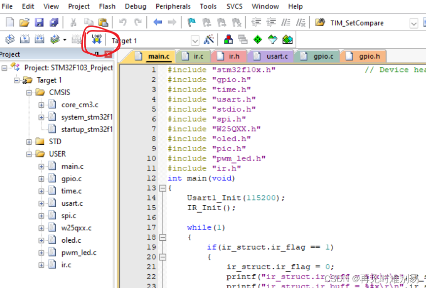
2、将代码写入工程,成功编译后,使用下载线将开发板连接到电脑,点击下载按钮,如下:
3、打开串口助手,调好串口和与代码相对应的波特率、数据位、停止位、校验位,然后打开串口;

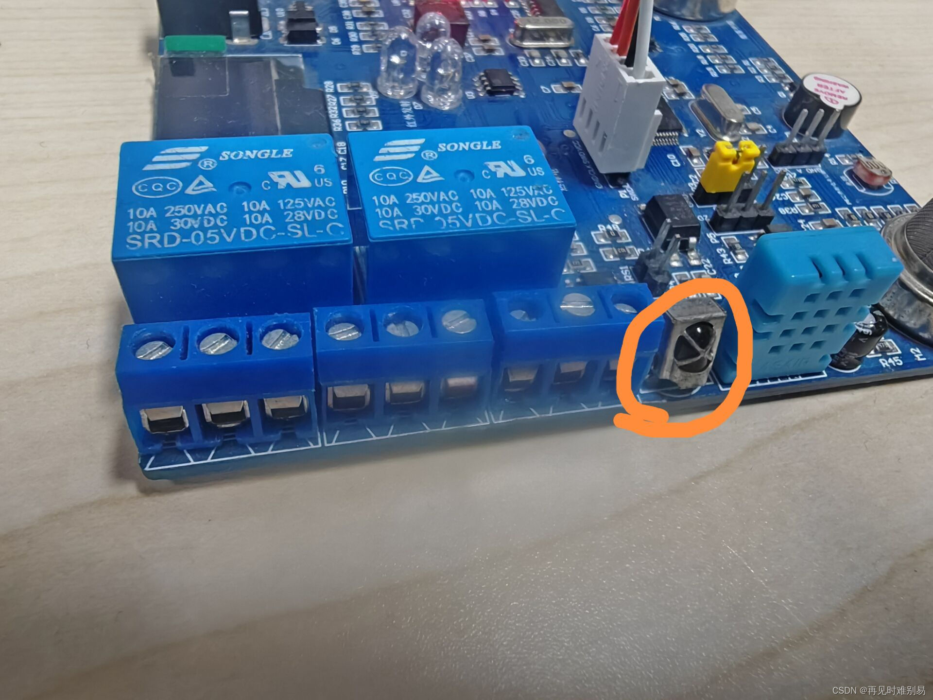
4、按一下开发板上的复位键,然后使用红外遥控器或者手机上的遥控软件对着开发板上的红外接收头按下按键,此时,串口助手上会接收到红外遥控器上发送的值。


二、代码部分
1、主函数
int main(void)
{
	Usart1_Init(115200);
	IR_Init();

	while(1)
	{
		if(ir_struct.ir_flag == 1)
		{
			ir_struct.ir_flag = 0;
			printf("ir_struct.ir_buff = %#x\r\n",ir_struct.ir_buff [0]);
			printf("ir_struct.ir_buff = %#x\r\n",ir_struct.ir_buff [1]);
			printf("ir_struct.ir_buff = %#x\r\n",ir_struct.ir_buff [2]);
			printf("ir_struct.ir_buff = %#x\r\n",ir_struct.ir_buff [3]);
			memset(&ir_struct,0,sizeof(ir_struct));
		}
	}
}
2、端口初始化函数
/*
硬件连接:
USART_TX --- PA9  --- 推挽复用输出
USART_RX --- PA10 --- 浮空输入或带上拉输入
模块名_Init
USART_Init
*/
/******************** USART模块初始化函数 *************************
Pclk:USART模块挂载总线时钟
Bound:USART模块所使用的波特率
*******************************************************************/
void Usart1_Init(u32 Bount)
{
	GPIO_InitTypeDef GPIO_InitStruct;
	USART_InitTypeDef USART_InitStruct;

	//GPIO
	RCC_APB2PeriphClockCmd(RCC_APB2Periph_GPIOA | RCC_APB2Periph_USART1,ENABLE); //开启A口时钟&&USART1时钟

	//PA9
	GPIO_InitStruct.GPIO_Mode = GPIO_Mode_AF_PP; //复用推挽输出
	GPIO_InitStruct.GPIO_Pin = GPIO_Pin_9; //端口9
	GPIO_InitStruct.GPIO_Speed = GPIO_Speed_50MHz; //输出速度为50MHZ

	GPIO_Init(GPIOA,&GPIO_InitStruct); //初始化A口

	//PA10
	GPIO_InitStruct.GPIO_Mode = GPIO_Mode_IN_FLOATING; //浮空输入
	GPIO_InitStruct.GPIO_Pin = GPIO_Pin_10; //端口10

	GPIO_Init(GPIOA,&GPIO_InitStruct); //初始化A口

	//USART1
	USART_InitStruct.USART_BaudRate = Bount; //设置波特率
	USART_InitStruct.USART_HardwareFlowControl = USART_HardwareFlowControl_None; //硬件流失能
	USART_InitStruct.USART_Mode = USART_Mode_Tx | USART_Mode_Rx; //使能发送接收
	USART_InitStruct.USART_Parity = USART_Parity_No; //奇偶校验失能
	USART_InitStruct.USART_StopBits = USART_StopBits_1;  //停止位长度为1bit
	USART_InitStruct.USART_WordLength = USART_WordLength_8b; //数据位长度为8bit
	USART_Init(USART1,&USART_InitStruct);//初始化USART1

	USART_ITConfig(USART1,USART_IT_RXNE,ENABLE); //接收中断

	//NVIC
	NVIC_SetPriority(USART1_IRQn,NVIC_EncodePriority(7-2,0,0)); //设置具体的中断源&&优先级
	NVIC_EnableIRQ(USART1_IRQn);//使能NVIC

	USART_Cmd(USART1,ENABLE); //使能串口模块
}
3、端口中断服务函数
u8  font_wtite_start = 0;               //开始接收串口数据标志
u32 rec_num = 0;    //字库存储地址
u8 rec_sta = 0;  //接收完毕标志 rec_sta=1,接收完毕
/********************** 串口中断服务函数 ************************************/
void USART1_IRQHandler(void)
{
	u8 temp= 0;
	if(USART_GetITStatus(USART1,USART_IT_RXNE))
	{
		TIM_Cmd(TIM2,DISABLE);  //关闭模块
		TIM2->CNT = 0;                            //计数器清零
		USART_ClearITPendingBit(USART1,USART_IT_RXNE);   //清标志
		font_wtite_start =1;  //开始接收标志
		rec_sta = 0;
		temp = USART1->DR;                         //读取接收到的数据
		W25QXX_Write_Page(rec_num++,1,&temp);      //把接收到的数据保存到W25Q64
		TIM_Cmd(TIM2,ENABLE);                      //启动定时器
	}
}
4、printf函数重写函数
/**********************printf底层函数**********************************/
int fputc(int data,FILE * file)
{
	while( !USART_GetFlagStatus(USART1,USART_FLAG_TC))
	{
		//轮询是否发送完成
	}
	USART_SendData(USART1,data);
	return data;
}
5、红外接收初始化函数
/***************************************
函数功能:红外接收初始化函数
硬件接口:
PB3-----TIM2_CH2----重映射
****************************************/
TIM_ICInitTypeDef TIM_ICInitStruct;
void IR_Init(void)
{
	GPIO_InitTypeDef GPIO_InitStruct;  //定义结构体变量
	TIM_TimeBaseInitTypeDef TIM_TimeBaseInitStruct;

	RCC_APB2PeriphClockCmd(RCC_APB2Periph_AFIO  |RCC_APB2Periph_GPIOB,ENABLE); //开启AFIO时钟

	GPIO_PinRemapConfig(GPIO_Remap_SWJ_JTAGDisable,ENABLE);  //将PC3重映射为PB3
	GPIO_PinRemapConfig(GPIO_FullRemap_TIM2,ENABLE);  //将PC3重映射为TIM2_CH2

	GPIO_InitStruct.GPIO_Pin = GPIO_Pin_3;   //端口为1口
	GPIO_InitStruct.GPIO_Mode = GPIO_Mode_IN_FLOATING;  //浮空输入
	GPIO_Init(GPIOB,&GPIO_InitStruct);

	RCC_APB1PeriphClockCmd(RCC_APB1Periph_TIM2,ENABLE); //开启TIM2时钟

	//时基单元
	TIM_TimeBaseInitStruct.TIM_ClockDivision = TIM_CKD_DIV1; //设置时钟分割
	TIM_TimeBaseInitStruct.TIM_CounterMode = TIM_CounterMode_Up; //向上计数
	TIM_TimeBaseInitStruct.TIM_Period = 0xffff; //设置计数周期
	TIM_TimeBaseInitStruct.TIM_Prescaler = 72-1; //设置分频值   1---1us
	TIM_TimeBaseInit(TIM2,&TIM_TimeBaseInitStruct);//65535us

	TIM_ICInitStruct.TIM_Channel = TIM_Channel_2; //使用定时器2的通道2
	TIM_ICInitStruct.TIM_ICSelection = TIM_ICSelection_DirectTI; //通道1使用捕获/比较1寄存器
	TIM_ICInitStruct.TIM_ICPrescaler = TIM_ICPSC_DIV1;//一个边沿捕获一次数值
	TIM_ICInitStruct.TIM_ICFilter = 0; //不滤波
	TIM_ICInitStruct.TIM_ICPolarity = TIM_ICPolarity_Falling; //下降沿触发
	TIM_ICInit(TIM2,&TIM_ICInitStruct);

	TIM_ITConfig(TIM2,TIM_IT_CC2,ENABLE); //设置捕获中断
	TIM_ITConfig(TIM2,TIM_IT_Update,ENABLE); //设置更新中断

	//	NVIC
	NVIC_SetPriority(TIM2_IRQn,NVIC_EncodePriority(7-2,0,0)); //设置具体的中断源&&优先级
	NVIC_EnableIRQ(TIM2_IRQn);//使能NVIC

	TIM_ClearITPendingBit(TIM2,TIM_IT_CC2); //清捕获/比较2标志
	TIM_ClearITPendingBit(TIM2,TIM_IT_Update); //清更新标志

	TIM_Cmd(TIM2,ENABLE); //使能计数器
}
6、TIM2中断服务函数
typedef struct
{
	u8 ir_flag;    //红外接受完成标志
	u8 ir_count;   //边沿个数
	u8 ir_data;    //红外接受到的数据
	u8 ir_buff[4]; //红外接受数据缓冲区
	u8 ir_buff_size; //红外接受数据缓冲区下标
}_IR;
_IR ir_struct;
u8 ir_time = 0; //记录进入更新的次数
u16 rt_time = 0; //保存当前捕获/比较数值
u16 low_time = 0; //保存低电平时间
u16 high_time = 0;//保存高电平时间
u8 ir_startflag = 0; //9ms的低和4.5ms的高是否正确  0:不正确  1:正确
u8 data_bit = 0; //记录接受到的数据位数
/********************中断服务函数*******************************/
void TIM2_IRQHandler(void)
{
	if(TIM_GetITStatus(TIM2,TIM_IT_CC2))  //是否发生捕获中断
	{//CCR2:捕获/比较寄存器2
		TIM_ClearITPendingBit(TIM2,TIM_IT_CC2); //清捕获/比较2标志
		rt_time = TIM_GetCapture2(TIM2); //获取捕获/比较寄存器2数值
		ir_struct.ir_count ++; //边沿个数+1
		if(ir_struct.ir_count == 1)
		{
			TIM_ICInitStruct.TIM_ICPolarity = TIM_ICPolarity_Rising; //上升沿触发
			TIM_ICInit(TIM2,&TIM_ICInitStruct);
			TIM_SetCounter(TIM2,0); //计数器清零
			return ;
		}
		if((ir_struct.ir_count != 1) &&(ir_struct.ir_count % 2 == 0))
		{
			low_time = rt_time; //保存低电平时间  9000
			TIM_ICInitStruct.TIM_ICPolarity = TIM_ICPolarity_Falling; //下降沿触发
			TIM_ICInit(TIM2,&TIM_ICInitStruct);
			TIM_SetCounter(TIM2,0); //计数器清零
		}
		else if((ir_struct.ir_count != 1) &&(ir_struct.ir_count % 2 != 0))
		{
			high_time = rt_time ; //获取高电平时间
			TIM_ICInitStruct.TIM_ICPolarity = TIM_ICPolarity_Rising; //上升沿触发
			TIM_ICInit(TIM2,&TIM_ICInitStruct);
			TIM_SetCounter(TIM2,0); //计数器清零
		}
		if((ir_startflag == 0) &&(ir_struct.ir_count == 3))
		{
			if((low_time >= 8500 && low_time <= 9500)&&(high_time>=4000 &&high_time<= 5000)) //判断低电平的时间是否是9000us
			{
				ir_startflag = 1; //9ms的低和4.5ms的高是正确
			}
			else//9ms的低和4.5ms的高出错
			{
				ir_startflag = 0;
				ir_struct.ir_count = 0;
				high_time = 0;
				low_time = 0;
				rt_time = 0;
				TIM_ICInitStruct.TIM_ICPolarity = TIM_ICPolarity_Falling; //下降沿触发
				TIM_ICInit(TIM2,&TIM_ICInitStruct);
			}
		}
		else if((ir_startflag == 1)&&(ir_struct.ir_count % 2 != 0))  // 5   7   9    11   13   15
		{ //接受40位数据
			if(low_time >= 500 && low_time <= 650)
			{
				ir_struct.ir_data >>= 1;//0000 0001
				if(high_time >= 1600 && high_time <= 1700) //接到1
				{
					ir_struct.ir_data |= 0x80; //1000 0000
				}
				data_bit++;
				if(data_bit >= 8)
				{
					data_bit = 0;
					ir_struct.ir_buff [ir_struct.ir_buff_size] = ir_struct.ir_data ;
					ir_struct.ir_buff_size ++;
					if(ir_struct.ir_buff_size >= 4)
					{
						ir_struct.ir_flag = 1;  //数据接受完毕
						TIM_ICInitStruct.TIM_ICPolarity = TIM_ICPolarity_Falling; //下降沿触发
						TIM_ICInit(TIM2,&TIM_ICInitStruct);
						ir_struct.ir_count = 0;
						ir_struct.ir_data = 0;
						ir_struct.ir_buff_size = 0;
					}
				}
			}
		}
	}
	else //是否发生更新中断
	{
		TIM_ClearITPendingBit(TIM2,TIM_IT_Update); //清更新标志
		ir_time++;//65*5ms
		if(ir_time >= 5)
		{
			ir_time = 0;
			TIM_ICInitStruct.TIM_ICPolarity = TIM_ICPolarity_Falling; //下降沿触发
			TIM_ICInit(TIM2,&TIM_ICInitStruct);
		}
	}

}
三、参考链接


 1696
1696


 被折叠的 条评论
为什么被折叠?
被折叠的 条评论
为什么被折叠?
 到【灌水乐园】发言


