


Encoder Interface 编码器接口
编码器接口可接收增量(正交)编码器的信号,根据编码器旋转产生的正交信号脉冲,自动控制CNT自增或自减,从而指示编码器的位置、旋转方向和旋转速度
每个高级定时器和通用定时器都拥有1个编码器接口
两个输入引脚借用了输入捕获的通道1和通道2
我们所用的是正交编码器,下图看一下正交编码器的波形图与边沿检测方式:
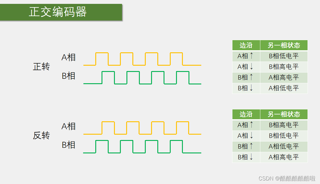
A相与B相相差90°,通过此来判断正反转,速度通过 加减计数器的值来确定。
下面来看编码器接口的基本结构:
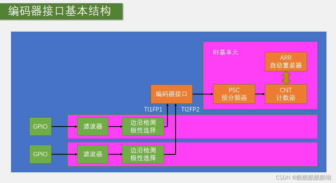
这个与输入捕获实验中的结构类似,但是少了后面的分频等步骤。需要注意的是这里编码器接管了时钟,不需要再开启内部时钟源了,两个GPIO输入,通过判断可以是CNT计数器响应的执行加减操作。
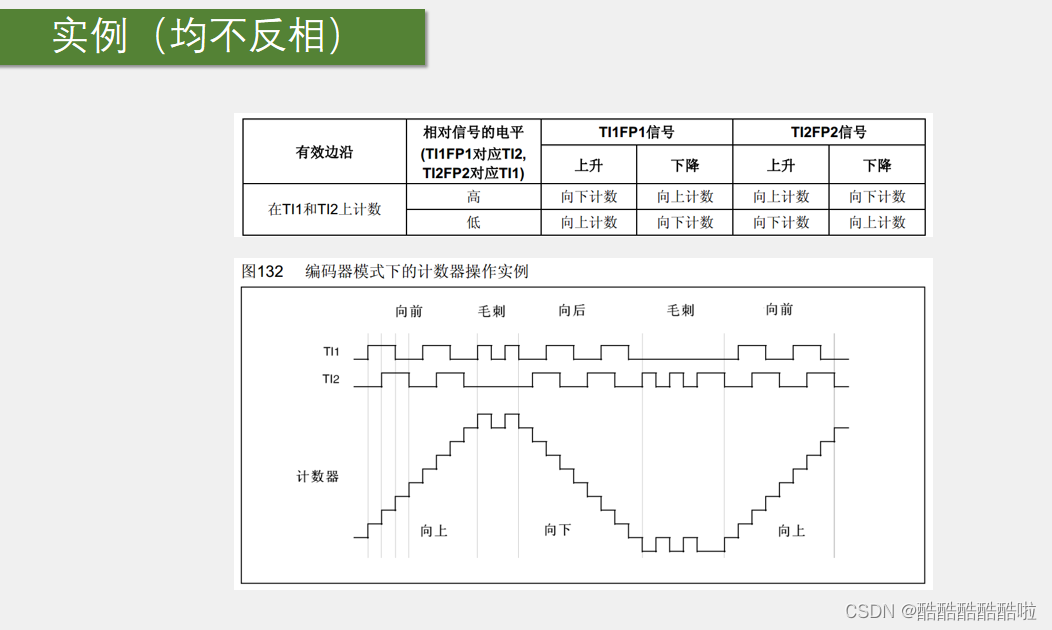
编码器的工作模式如下图:

本次实验选择连个都计数的模式 ,下面列举一个例子来看其加减的方式:
下面来看实验,本次实验使用定时器定了一个一秒的时间来读取CNT计数器的值,可以相当于编码器测速了。
Encoder.c文件:
#include "stm32f10x.h"                  // Device header

void Encoder_Init(void)
{
	RCC_APB1PeriphClockCmd(RCC_APB1Periph_TIM3, ENABLE);
	RCC_APB2PeriphClockCmd(RCC_APB2Periph_GPIOA, ENABLE);

	GPIO_InitTypeDef GPIO_InitStructure;
	GPIO_InitStructure.GPIO_Mode = GPIO_Mode_IPU;
	GPIO_InitStructure.GPIO_Pin = GPIO_Pin_6 | GPIO_Pin_7;
	GPIO_InitStructure.GPIO_Speed = GPIO_Speed_50MHz;
	GPIO_Init(GPIOA, &GPIO_InitStructure);

//	TIM_InternalClockConfig(TIM3);


	TIM_TimeBaseInitTypeDef TIM_TimeBaseInitStruct;
	TIM_TimeBaseInitStruct.TIM_ClockDivision = TIM_CKD_DIV1;
	TIM_TimeBaseInitStruct.TIM_CounterMode = TIM_CounterMode_Up;
	TIM_TimeBaseInitStruct.TIM_Period = 65536 - 1;  // ARR
	TIM_TimeBaseInitStruct.TIM_Prescaler = 1 -1;   //PSC
	TIM_TimeBaseInitStruct.TIM_RepetitionCounter = 0;
	TIM_TimeBaseInit(TIM3, &TIM_TimeBaseInitStruct);

	TIM_ICInitTypeDef TIM_ICInitStruct;
	TIM_ICStructInit(&TIM_ICInitStruct);

	TIM_ICInitStruct.TIM_Channel = TIM_Channel_1;  // TIM_CH channel select
	TIM_ICInitStruct.TIM_ICFilter = 0xF;
	TIM_ICInitStruct.TIM_ICPolarity = TIM_ICPolarity_Rising;
	TIM_ICInit(TIM3, &TIM_ICInitStruct);
	TIM_ICInitStruct.TIM_Channel = TIM_Channel_2;  // TIM_CH channel select
	TIM_ICInitStruct.TIM_ICFilter = 0xF;
	TIM_ICInitStruct.TIM_ICPolarity = TIM_ICPolarity_Rising;
	TIM_ICInit(TIM3, &TIM_ICInitStruct);

	TIM_EncoderInterfaceConfig(TIM3, TIM_EncoderMode_TI12, TIM_ICPolarity_Rising, TIM_ICPolarity_Rising);

	TIM_Cmd(TIM3, ENABLE);

}

int16_t Encoder_Get(void)
{

	int16_t Temp;
	Temp = TIM_GetCounter(TIM3);
	TIM_SetCounter(TIM3, 0);
	return Temp;

}
Encoder.h文件:
#ifndef __ENCODER_H
#define __ENCODER_H

void Encoder_Init(void);
int16_t Encoder_Get(void);

#endif
main.c文件:
#include "stm32f10x.h"                  // Device header
#include "Delay.h"
#include "OLED.h"
#include "Timer.h"
#include "Encoder.h"
int16_t Speed;

int main(void)
{
	OLED_Init();
	Timer_Init();
	Encoder_Init();
//	OLED_ShowString(1, 1, "Num:");
//	OLED_ShowString(2, 1, "CNT:");
	OLED_ShowString(1, 1, "speed:");
	while (1)
	{
		OLED_ShowSignedNum(1, 7, Speed, 5);
	}
}
Timer.c文件:(定时器文件)
#include "stm32f10x.h" // Device header
#include "Encoder.h"
extern int16_t Speed;
void Timer_Init(void)
{
RCC_APB1PeriphClockCmd(RCC_APB1Periph_TIM2, ENABLE);
TIM_InternalClockConfig(TIM2);
TIM_TimeBaseInitTypeDef TIM_TimeBaseInitStruct;
TIM_TimeBaseInitStruct.TIM_ClockDivision = TIM_CKD_DIV1;
TIM_TimeBaseInitStruct.TIM_CounterMode = TIM_CounterMode_Up;
TIM_TimeBaseInitStruct.TIM_Period = 10000 - 1; // ARR
TIM_TimeBaseInitStruct.TIM_Prescaler = 7200- 1; // PSC
TIM_TimeBaseInitStruct.TIM_RepetitionCounter = 0; // ¸ß¼¶¶¨Ê±Æ÷ËùÐèÒªµÄ
TIM_TimeBaseInit(TIM2, &TIM_TimeBaseInitStruct);
TIM_ClearFlag(TIM2, TIM_FLAG_Update);
TIM_ITConfig(TIM2, TIM_IT_Update, ENABLE);
NVIC_PriorityGroupConfig(NVIC_PriorityGroup_2);
NVIC_InitTypeDef NVIC_InitStruct;
NVIC_InitStruct.NVIC_IRQChannel = TIM2_IRQn;
NVIC_InitStruct.NVIC_IRQChannelCmd = ENABLE;
NVIC_InitStruct.NVIC_IRQChannelPreemptionPriority = 1; // ÇÀÕ¼ÓÅÏȼ
NVIC_InitStruct.NVIC_IRQChannelSubPriority = 1; //ÏìÓ¦ÓÅÏȼ
NVIC_Init(&NVIC_InitStruct);
TIM_Cmd(TIM2, ENABLE);
}
uint16_t Timer_GetCounter(void)
{
return TIM_GetCounter(TIM2);
}
void TIM2_IRQHandler(void)
{
if(TIM_GetITStatus(TIM2, TIM_IT_Update) == SET)
{
Speed = Encoder_Get();
TIM_ClearITPendingBit(TIM2, TIM_IT_Update);
}
}
Timer.h文件:
#ifndef __TIMER_H
#define __TIMER_H

void Timer_Init(void);
uint16_t Timer_GetCounter(void);
#endif


 被折叠的 条评论
为什么被折叠?
被折叠的 条评论
为什么被折叠?
 到【灌水乐园】发言


