


led.c
#include "led.h"

void led_init(void)
{
	RCC_APB2PeriphClockCmd(LED_CLK, ENABLE);

	GPIO_InitTypeDef	GPIO_InitStructure;

	//配置GPIO引脚
	GPIO_InitStructure.GPIO_Pin=LED_PIN;
	GPIO_InitStructure.GPIO_Mode=GPIO_Mode_Out_PP;	//选择引脚功能
	GPIO_InitStructure.GPIO_Speed=GPIO_Speed_50MHz;	//选择引脚速度
	GPIO_Init(LED_PORT, &GPIO_InitStructure); 			//初始化GPIO
}
led.h
#ifndef __LED_H
#define __LED_H

#include "stm32f10x.h"

#define LED_PIN		GPIO_Pin_11
#define LED_PORT	GPIOB
#define LED_CLK		RCC_APB2Periph_GPIOB

void led_init(void);

#endif /* __LED_H */
key.c
#include "key.h"

void key_init(void)
{
	// 打开时钟线
	RCC_APB2PeriphClockCmd(KEY1_CLK, ENABLE);
	RCC_APB2PeriphClockCmd(KEY2_CLK, ENABLE);

	GPIO_InitTypeDef GPIO_InitStructure;

	GPIO_InitStructure.GPIO_Pin = KEY1_PIN;
	GPIO_InitStructure.GPIO_Mode = GPIO_Mode_IPU; // 上拉输入,即:上拉到高电平,只有捕获到低电平时读数为0
	GPIO_Init(KEY1_PORT, &GPIO_InitStructure);

	GPIO_InitStructure.GPIO_Pin = KEY2_PIN;
	GPIO_InitStructure.GPIO_Mode = GPIO_Mode_IPU;
	GPIO_Init(KEY2_PORT, &GPIO_InitStructure);
}

uint8_t Key_Scan(GPIO_TypeDef* GPIOx,uint16_t GPIO_Pin)
{
	/*检测是否有按键按下 */
	if(GPIO_ReadInputDataBit(GPIOx,GPIO_Pin) == 0 )
	{
		/*等待按键释放*/
		while(GPIO_ReadInputDataBit(GPIOx,GPIO_Pin) == 0);
		return 1;
	}
	else
		return 0;
}
key.h
#ifndef __KEY_H
#define __KEY_H

#include "stm32f10x.h"

#define KEY1_PIN	GPIO_Pin_13
#define KEY1_PORT	GPIOC
#define KEY1_CLK	RCC_APB2Periph_GPIOC

#define KEY2_PIN	GPIO_Pin_14
#define KEY2_PORT	GPIOC
#define KEY2_CLK	RCC_APB2Periph_GPIOC

void key_init(void);
uint8_t Key_Scan(GPIO_TypeDef* GPIOx, uint16_t GPIO_Pin);

#endif /* __KEY_H */
main.c
#include "stm32f10x.h"
#include "delay.h"
#include "key.h"
#include "led.h"


int main(void)
{
	// 初始化
	delay_init();
	key_init();
	led_init();
	delay_ms(100);

	while (1)
	{
		if(Key_Scan(KEY1_PORT, KEY1_PIN) == 1)
		{
			GPIO_SetBits(LED_PORT,LED_PIN);
		}
		if(Key_Scan(KEY2_PORT, KEY2_PIN) == 1)
		{
			GPIO_ResetBits(LED_PORT,LED_PIN);
		}
	}
}
/*********************************************END OF FILE**********************/
注意:
1.led灯连接的引脚需要设置它的模式为GPIO_Mode_Out_PP,并利用函数GPIO_SetBits(PORT,PIN)和GPIO_ResetBits(PORT,PIN)控制引脚输出高电平1或低电平0。
2.按钮检测的引脚需要设置它的模式为GPIO_Mode_IPU(上拉输入)。上拉到高电平1,只有捕获到低电平时读数为0(配合函数GPIO_ReadInputDataBit(GPIOx,GPIO_Pin)读取引脚电位)。
附上按钮的图片
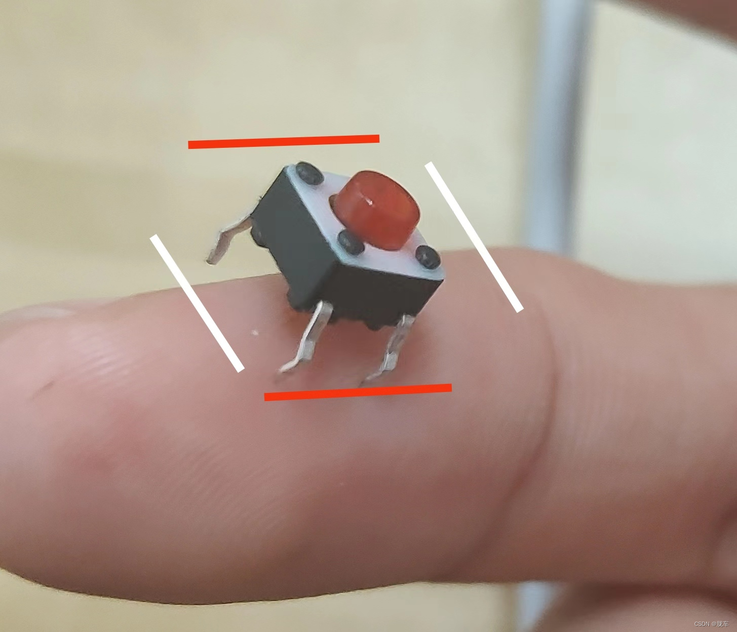
白色相连的引脚自然导通,红色的不通;当按钮按下时全部导通。


 9649
9649


 被折叠的 条评论
为什么被折叠?
被折叠的 条评论
为什么被折叠?
 到【灌水乐园】发言


