


CAN BUS 原理 网上资料非常丰富,是车载系统主要BUS之一。
我们关注如下方面
- can bus 是什么
- 网络结构
- CAN BUS 协议
- ECU node
- 实现
- 其他
What is CAN Bus?
Control Area Network (CAN) bus is a serial communication protocol that allows devices to exchange data in a reliable and efficient way. It is widely used in vehicles, working like a nervous system to connect ECUs in the vehicle.
CAN bus was originally designed for automotive applications by Bosch in the 1980s. It is a multi-master, multi-slave, half-duplex, and fault-tolerant protocol that fits well with the requirements of automotive applications. It is simple, low-cost, and reliable and can be used in harsh environments. The CAN bus provides one point of entry for all the ECUs in the vehicle, which makes it easy to connect and diagnose.
CAN bus data can provide valuable insights into the performance and status of the connected devices. However, collecting and processing CAN bus data can be challenging due to the high data rate, low bandwidth, and variable network conditions.
One possible solution to overcome these challenges is to use MQTT, enabling timely data transmission from cars to cloud even with weak network conditions. EMQX is an open-source MQTT broker that can help you build a reliable and scalable MQTT infrastructure for collecting CAN bus data.


Message Structure in the CAN Protocol
The message structure in a CAN bus system is crucial for efficient communication between devices. The protocol uses a data frame format that consists of several fields, including an identifier, control field, data field, and error detection mechanism.
- Identifier: This unique value determines the priority of each message on the network. In standard 11-bit identifiers (CAN 2.0A), there are up to 2048 different priorities available. Extended 29-bit identifiers (CAN 2.0B) provide even more options with over half a billion distinct values.
- Data Length Code (DLC): Located within the control field, this code specifies how many bytes are present in the data field - ranging from zero to eight bytes.
- Data Field: Contains actual information being transmitted across nodes in byte-sized segments.
- Cyclic Redundancy Check (CRC): A built-in error detection mechanism that ensures reliable communication by detecting transmission errors and requesting retransmission if necessary.
- Acknowledgment Slot: A single bit used by receiving nodes to acknowledge successful receipt of messages or indicate errors requiring retransmission.
- Error Frame: An optional part of CAN messaging that allows nodes to signal when they detect an issue with their own transmissions or received messages from other devices on the network.
Types of CAN
Here are the three main types of CAN:
Low-Speed CAN
Low-Speed CAN, also known as fault-tolerant or ISO 11898-3, operates at speeds up to 125 kbps. It is designed for less critical systems like body control modules, door locks, window controls, etc., where data transmission speed isn't vital. Its key feature is the ability to continue functioning even when one wire in the bus fails.
High-Speed CAN
High-Speed CAN, or ISO 11898-2, can reach speeds up to 1 Mbps. This type of network is suitable for more time-sensitive applications such as engine management systems and electronic braking systems due to its faster data transfer rates compared to low-speed counterparts. However, it lacks fault tolerance capabilities found in low-speed networks.
CAN FD (Flexible Data Rate)
CAN FD, introduced by Bosch in 2012, is an extension of high-speed networks with increased data rates—up to 5 Mbps—while maintaining backward compatibility with existing high-speed devices. The primary advantage of this technology lies in its ability to transmit larger payloads more efficiently than traditional CAN, making it ideal for modern vehicles with increasingly complex electronic systems.
ps:CAN Bus: How It Works, Pros and Cons, and Fast Local Processing Tutorial - DEV Community
ECU:


(收发器与控制器)
Node design
- Microcontroller
- process information such as sensor inputs or outputs to turn on lights or an actuator
- can also process information to control a dashboard or another kind of communication
- CAN controller
- converts digital information to messages on the bus
- Transceiver
- Connection to a sensor / actuator / display
对比:
| Parameter | SPI | I2C | CAN |
| Speed | 3Mbps to 10Mbps | Standard: 100Kbps | 10KBps to 1MBps Also depends upon length of wire used |
| Fast: 400 Kbps | |||
| Highspeed:3.4Mbps | |||
| Type | Synchronous | Synchronous | Asynchronous |
| Number of Wires | 3+ (MISO, MOSI, SCK, SS1, SS2…SS(n)) | 2 wires (SDA, SCL) | 2 wires (CAN_H, CAN_L) |
| Duplex | Full Duplex | Half Duplex | Half Duplex |
CAN Protocol Applications
ardunio: 后续高档的板子 内置了can controller,但是否内置了tranceiver,我还要查一下:没内置can bus 部件的板子,需要外接如MCP2515 CAN Module
when the Arduino doesn’t contain any inbuilt CAN port, a CAN module called MCP2515 is used. This CAN module is interfaced with Arduino by using the SPI communication. Let’s see about more about MCP2515 in detail and how it is interfaced with Arduino.
MCP2515 CAN Module:
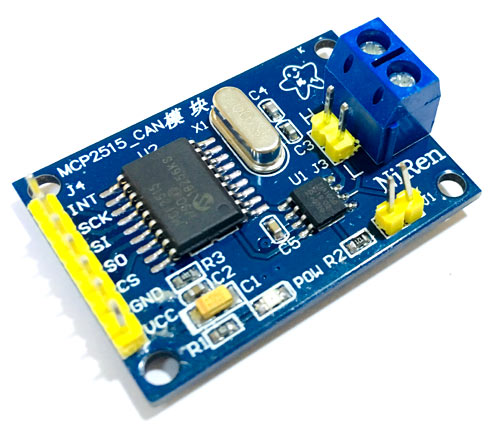
MCP2515 Module has a CAN controller MCP2515 which is high speed CAN transceiver. The connection between MCP2515 and MCU is through SPI. So, it is easy to interface with any microcontroller having SPI interface.
For beginners who want to learn CAN Bus, this module will act as a good start. This CAN SPI board is ideal for industrial automation, home automation and other automotive embedded projects.
Features and Specification of MCP2515:
- Uses High-speed CAN transceiver TJA1050
- Dimension: 40×28mm
- SPI control for expand Multi CAN bus interface
- 8MHZ crystal oscillator
- 120Ω terminal resistance
- Has independent key, LED indicator, Power indicator
- Supports 1 Mb/s CAN operation
- Low current standby operation
- Up to 112 nodes can be connected
let’s see how to send humidity & temperature (DHT11) sensor data from Arduino Nano to Arduino Uno via CAN bus module MCP2515.Components Required
- Arduino UNO
- Arduino NANO
- DHT11
- 16x2 LCD Display
- MCP2515 CAN Module – 2
- 10k Potentiometer
- Breadboard
- Connecting Wires
MCP2515 Arduino Circuit Diagram:

code:
CAN Transmitter Code (Arduino Nano):


#include <SPI.h>          //Library for using SPI Communication

#include <mcp2515.h>      //Library for using CAN Communication

#include <DHT.h>          //Library for using DHT sensor


#define DHTPIN A0

#define DHTTYPE DHT11


struct can_frame canMsg;

MCP2515 mcp2515(10);


DHT dht(DHTPIN, DHTTYPE);     //initilize object dht for class DHT with DHT pin with STM32 and DHT type as DHT11


void setup()

{

  while (!Serial);

  Serial.begin(9600);


  SPI.begin();               //Begins SPI communication

  dht.begin();               //Begins to read temperature & humidity sesnor value


  mcp2515.reset();

  mcp2515.setBitrate(CAN_500KBPS,MCP_8MHZ); //Sets CAN at speed 500KBPS and Clock 8MHz

  mcp2515.setNormalMode();

}


void loop()

{

  int h = dht.readHumidity();       //Gets Humidity value

  int t = dht.readTemperature();    //Gets Temperature value


  canMsg.can_id  = 0x036;           //CAN id as 0x036

  canMsg.can_dlc = 8;               //CAN data length as 8

  canMsg.data[0] = h;               //Update humidity value in [0]

  canMsg.data[1] = t;               //Update temperature value in [1]

  canMsg.data[2] = 0x00;            //Rest all with 0

  canMsg.data[3] = 0x00;

  canMsg.data[4] = 0x00;

  canMsg.data[5] = 0x00;

  canMsg.data[6] = 0x00;

  canMsg.data[7] = 0x00;

  mcp2515.sendMessage(&canMsg);     //Sends the CAN message

  delay(1000);

}


CAN Receiver Code (Arduino UNO):


#include <SPI.h>              //Library for using SPI Communication

#include <mcp2515.h>          //Library for using CAN Communication

#include <LiquidCrystal.h>    //Library for using LCD display


const int rs = 3, en = 4, d4 = 5, d5 = 6, d6 = 7, d7 = 8;


LiquidCrystal lcd(rs, en, d4, d5, d6, d7);  //Define LCD display pins RS,E,D4,D5,D6,D7


struct can_frame canMsg;

MCP2515 mcp2515(10);                 // SPI CS Pin 10


void setup() {

  lcd.begin(16,2);                   //Sets LCD as 16x2 type

  lcd.setCursor(0,0);                //Display Welcome Message

  lcd.print("CIRCUIT DIGEST");

  lcd.setCursor(0,1);

  lcd.print("CAN ARDUINO");

  delay(3000);

  lcd.clear();


  SPI.begin();                       //Begins SPI communication


  Serial.begin(9600);                //Begins Serial Communication at 9600 baudrate


  mcp2515.reset();

  mcp2515.setBitrate(CAN_500KBPS,MCP_8MHZ); //Sets CAN at speed 500KBPS and Clock 8MHz

  mcp2515.setNormalMode();                  //Sets CAN at normal mode

}


void loop()

{

  if (mcp2515.readMessage(&canMsg) == MCP2515::ERROR_OK) // To receive data (Poll Read)

  {

     int x = canMsg.data[0];

     int y = canMsg.data[1];


      lcd.setCursor(0,0);          //Display Temp & Humidity value received at 16x2 LCD

      lcd.print("Humidity : ");

      lcd.print(x);

      lcd.setCursor(0,1);

      lcd.print("Temp : ");

      lcd.print(y);

      delay(1000);

      lcd.clear();

    }

}ps:Arduino CAN Tutorial - Interfacing MCP2515 CAN BUS Module with Arduino

Arduino DUE开发板:
它内置can bus controller,但是 没有内置收发器,因此,需要连接收发器:

参见:
https://openinverter.org/wiki/CAN_bus_with_Arduino_DueCAN bus with Arduino Due - openinverter.org wiki


 1万+
1万+

 被折叠的 条评论
为什么被折叠?
被折叠的 条评论
为什么被折叠?
 到【灌水乐园】发言


