


 本文档详细介绍了Amplify Shader Editor (ASE) 的安装、编辑器使用方法、画布UI交互等内容,涵盖了材质和着色器模式、输出节点配置及着色器函数的创建与使用等核心功能。还介绍了快捷键的使用、半透明效果的实现方法以及第三方兼容性等方面的知识。
本篇文章翻译自Amplify Shader Editor官方文档原文链接:http://wiki.amplify.pt/index.php?title=Unity_Products:Amplify_Shader_Editor/Manual Contents
安装(Installation)1. Open AmplifyshaderEditor###.unitypackage 1. 打开AmplifyshaderEditor###.unitypackage 2. After Unity loads it will display the “Importing package” window, select All and click Import 2. Unity加载后将显示“导入包”窗口,选择All,点击Import 3. Amplify Shader Editor should now be installed in your Unity project and it should have the following directory structure: 3.现在应该在你的Unity项目中安装Amplify Shader编辑器,它应该有以下目录结构: YourProject\Assets\AmplifyshaderEditor\ YourProject\Assets\AmplifyshaderEditor\Plugins\ YourProject\Assets\AmplifyshaderEditor\Resources\ YourProject\Assets\AmplifyshaderEditor\Samples\ YourProject\Assets\AmplifyshaderEditor\Templates\ YourProject\Assets\AmplifyshaderEditor\Textures\ 编辑器(The Editor)
Open the Amplify Shader Editor canvas, dock it, use it in a separate window, or even another monitor. The editor opens automatically when you double-click an ASE material or shader. 打开Amplify Shader Editor画布,停靠它,在一个单独的窗口中使用它,甚至在另一个监视器中使用它。双击ASE材质或着色器时,编辑器将自动打开。
ASE shaders can be created directly in the Project tab or via the Menu under Assets > Create > Shader > Amplify Surface Shader. ASE着色器可以直接创建在项目标签或通过菜单下的Assets > Create > Shader > Amplify Surface Shader.
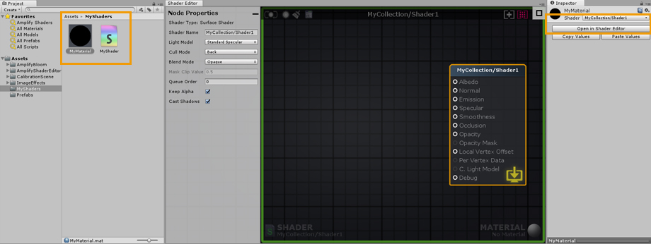
1. Double-click an ASE shader to open it in the ASE canvas. Alternatively, you can open the shader directly in its inspector tab by clicking on the Open in Shader Editor button. 1. 双击ASE着色器在ASE画布中打开它。或者,你也可以通过点击open in shader Editor按钮,在它的inspector选项卡中直接打开着色器。 2. Name your shader directly in the Node Properties tab, you can add your own category by using a forward slash (/) separator. Keep in mind that shader file names are unique and have to be set manually in the Project Explorer tab. You can use different names for the file and actual shader. 2. 在节点属性标签中直接命名你的着色器,你可以使用斜杠(/)分隔符添加你自己的类别。请记住,着色器文件名是唯一的,必须在Project Explorer选项卡中手动设置。你可以为文件和实际的着色器使用不同的名字。 3. This area shows the current shader, clicking it will locate and select the shader in the Project Explorer tab. Notice the green outline, it’s a visual aid that lets you know that only the shader is currently open. 3.该区域显示当前的着色器,单击它将在Project Explorer选项卡中找到并选择着色器。注意绿色的轮廓,它是一个视觉辅助工具,让你知道目前只有着色器是开放的。
1. Double-click a material that uses an ASE shader to open both the shader and the material in the ASE canvas. Alternatively, you can open it directly in the material inspector tab by clicking on the Open in Shader Editor button. 1. 双击使用ASE着色器的材质来打开ASE画布中的着色器和材质。或者,你也可以直接在材质检查器选项卡中打开它,方法是点击open in Shader Editor按钮。 2. By opening the material, both the active shader and material are shown in the lower canvas area. As with the shader, clicking on it will locate and select the material in the Project Explorer tab. Notice the blue outline, it’s a visual aid that lets your know that both the shader and material are currently open. 2. 通过打开材质,活动着色器和材质都显示在下面的画布区域。与着色器一样,单击它将在Project Explorer选项卡中找到并选择材质。注意蓝色的轮廓,它是一个视觉辅助,让你知道着色器和材质都是打开的。 Canvas UI Interaction
1. Node properties can be adjusted in the left tab. Select a node, or the Output Node, to reveal its parameters. Some values can be adjusted directly in the actual node. Output Node properties are always shown on this tab if no node or multiple nodes are selected. The Output Node Properties tab can be minimized by clicking the minus button in the upper right corner of the tab. 1. 节点属性可以在左侧选项卡中进行调整。选择一个节点或输出节点,以显示其参数。一些值可以在实际节点中直接进行调整。如果没有选择节点或多个节点,则输出节点属性总是显示在此选项卡上。通过单击选项卡右上角的减号按钮,可以最小化Output Node Properties选项卡。 2. Minimalist Save/Update/Clear/Edit buttons. Gray when unavailable or disabled, green when up-to-date, yellow when outdated. 2. 极简主义的保存/更新/清除/编辑按钮。不可用或禁用时为灰色,最新时为绿色,过时时为黄色。 Button 1: Manual shader update (Save and Update) 按钮1:手动着色器更新(保存和更新) Button 2: Toggle LIVE shader update (Save and Update Automatically) 按钮2:切换实时着色器更新(自动保存和更新) Button 3: Remove disconnected nodes 按钮3:删除断开的节点 Button 4: Open shader in Text Editor 按钮4:在文本编辑器中打开着色器 3. Shader category and name. 3.着色器类别和名称。 4. Canvas view adjustment. 4. 画布视图调整。 Button 1: Select and focus on the Output Node 按钮1:选择并聚焦于输出节点 Button 2: Focus on selected nodes, will focus on the entire node collection if nothing is selected. Automatic zoom is also done by double clicking the button or double pressing the ‘F’ key 按钮2:聚焦于选中的节点,如果没有选中任何节点,则聚焦于整个节点集合。自动缩放也可以通过双击按钮或双击“F”键来实现 5. The Node Palette tab is a searchable node list where you can select and drag out nodes directly onto the canvas area. The Node Palette tab can be minimized by clicking the minus button in the upper left corner of the tab. 5. Node Palette选项卡是一个可搜索的节点列表,您可以在其中直接选择并将节点拖出画布区域。通过单击选项卡左上角的减号按钮,可以最小化Node Palette选项卡。 6. Right-click anywhere on the canvas to bring up a searchable node list, click on the node name to create it. 6. 右键单击画布上的任何地方,以弹出可搜索的节点列表,单击节点名创建它。 7. Hold a shortcut key and click anywhere on the canvas to create a new node. Shortcut keys are shown inside [ ] placed in front of their respective node names on the Palette Tab. For example: Key ‘1’ for a Float and Key ‘5’ for a Color node. 7. 按住快捷键并单击画布上的任意位置以创建新节点。快捷键显示在[]内部,位于面板选项卡上它们各自的节点名前面。例如:Key ' 1 '表示浮点数,Key ' 5 '表示颜色节点。
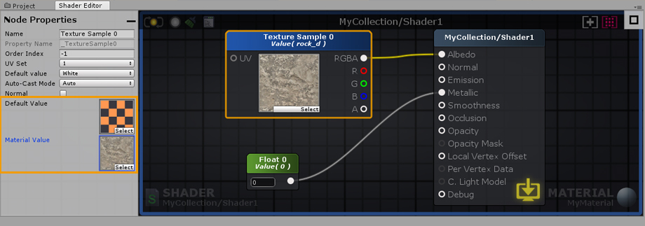
Data flows from left to right – Input Port > Processed Data > Output Port. Only nodes directly or indirectly connected to a Output Node are analyzed and used to generate the final shader instructions. If a node contains unconnected Input Ports, ASE will use internal data during the processing phase. Internal data values can be edited via the Node Property tab. 数据从左到右流动——输入端口>处理数据>输出端口。只分析直接或间接连接到输出节点的节点,并用于生成最终的着色器指令。如果一个节点包含未连接的输入端口,ASE将在处理阶段使用内部数据。可以通过Node属性选项卡编辑内部数据值。
Nodes Nodes can be selected by either left mouse clicking on them or left mouse drag a box selection over them. Nodes can be appended or removed from a selection by holding the ‘Shift’ key and clicking on it. Press ‘CTRL/CMD+A’ to select everything. Deselect everything by left mouse clicking over an empty space on the node canvas. Move selected nodes by holding your left mouse button over them and dragging. Nodes 可以通过鼠标左键单击节点或鼠标左键拖动选中的框来选择节点。通过按住Shift键并单击它,可以从选择中添加或删除节点。按下CTRL/CMD+A键选择所有选项。通过鼠标左键单击节点画布上的空白区域取消所有选择。通过按住鼠标左键并拖动选定的节点来移动它们。 Wires Delete a wire by holding the ‘Alt’ key and clicking on a node port or drag a connection to an empty canvas space and left click. Wires connected to selected nodes are highlighted to denote data flow, from the leftmost node to the rightmost node. Wires 通过按住“Alt”键并单击节点端口或拖动到空白画布空间的连接并单击左键,删除连线。连接到所选节点的连接被高亮显示,以表示从最左边节点到最右边节点的数据流。 Connections Create connection by left clicking and dragging a wire either from an output port into an input or from an empty input port to an output port. Left mouse holding on a already connected input port removes wire ending from it and locks it to the mouse cursor so you can drag it to another port. Drag a wire onto an empty canvas space and the context menu automatically appears and if a node type is selected a connection is made with the first valid port. Connections 通过左键点击并拖动连线(从输出端口到输入端口或从空输入端口到输出端口)创建连接。在已经连接的输入端口上按住鼠标左键,可以将连接端从它移开,并将其锁定到鼠标指针上,这样您就可以将它拖到另一个端口上。将导线拖到空画布空间上,上下文菜单将自动出现,如果选择了节点类型,则使用第一个有效端口进行连接。 Ports Output ports can be connected to multiple input ports but input ports accept a single input. Wires automatically snap to ports near the mouse cursor. For easier use, the active port area is quite forgiving, you can even drop your wires directly onto the port name. Ports 输出端口可以连接到多个输入端口,但输入端口接受单个输入。连线自动吸附到鼠标光标附近的端口。为了更容易使用,活动端口区域是相当宽容的,您甚至可以直接将连接放到端口名称上。 View Right mouse or middle mouse button drag to pan the view. The canvas will scroll automatically when box selecting or moving selected nodes away from the visible workspace area. You can Zoom In/Out via the mouse scroll wheel. The amount of zoom out is dynamically determined from the nodes positioning on the canvas. View 鼠标右键或鼠标中键拖动可平移视图。当框选择或从可见工作区区域移动选定节点时,画布将自动滚动。你可以通过鼠标滚轮放大/缩小。缩放的大小是根据画布上的节点位置动态确定的。 Tabs Both the Node Properties and Node Palette windows are automatically minimized when reducing the ASE window width below a value of 750px. You can always maximize them by clicking the rectangular button. Tabs 当将ASE窗口宽度降低到750px以下时,节点属性和节点面板窗口都会自动最小化。您总是可以通过单击矩形按钮来最大化它们。 材质和着色器模式(Material and Shader Mode)
You can work with ASE in one of two modes, shader or material, depending if you load the shader file from a shader or a material asset. The canvas border serves as a visual indicator of the active mode, a green outline is shown for the shader mode and a blue outline for the material mode. 你可以使用ASE在两种模式之一,着色器或材质,取决于你是否从材质或材质资源加载着色器文件。画布边框作为活动模式的视觉指示器,一个绿色的轮廓显示为着色模式,一个蓝色的轮廓显示为材质模式。
Values set in a shader are commonly referred to as Default Values. Any changes made to the Default Values of any given shader will automatically affect all materials using it. When simultaneously editing a material and shader, pay close attention to which values are being altered. 在着色器中设置的值通常称为默认值。对任何给定着色器的默认值所做的任何更改都会自动影响使用它的所有材质。当同时编辑材质和着色器时,要密切注意哪些值正在被修改。
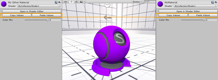
Unlike the Default Values in a shader, material values can be unique. material values are only shown when working in the material mode ( with both material and shader opened ). Only nodes which represent variables ( Color, Float, Int, Vector, Matrix ) have a Parameter Type dropdown and can be set to Property. Default values are always copied to material values when selecting Property or Uniform parameter type. Each material can be adjusted in order to create an unlimited number of variations, while still using the same shader. You can think of your materials as instances of your shader, each instance is unique but created using the same set of Default Values. 与着色器中的默认值不同,材质值可以是唯一的。材质值只在材质模式下显示(打开材质和材质)。只有表示变量(颜色、浮点数、Int、向量、矩阵)的节点具有参数类型下拉菜单,并且可以设置为属性。在选择属性或统一参数类型时,默认值总是被复制到材质值。每一种材质都可以调整,以创造无限数量的变化,同时仍然使用相同的着色器。你可以把材质当成你的着色器的实例,每个实例都是唯一的,但是使用相同的默认值创建。
You can Copy and Paste property values between materials using the same ASE shader. The Open in Shader Editor button provides a quick way to open both the material and shader used in the Amplify Shader Editor. 您可以复制和粘贴属性值之间的材质使用相同的ASE着色器。打开在着色器编辑器按钮提供了一个快速的方式来打开材质和着色器中使用的Amplify着色器编辑器。
Shaders can also be opened directly via their inspector tab by clicking on the Open in Shader Editor button. Alternatively, click on Open in Text Editor to open it in your current code editor. 着色器也可以通过他们的检查器标签直接打开,通过点击打开在着色器编辑器按钮。或者,单击文本编辑器中的Open以在当前的代码编辑器中打开它。 输出节点(Output Node)Portions of this section have been acquired directly from the Unity Shader Reference documentation. 本节的部分内容是直接从Unity Shader参考文档中获得的。 Learn more: Unity Shader Reference
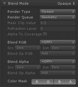
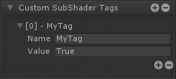
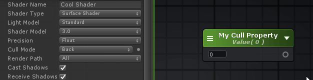
Referencing Custom Properties引用自定义属性 Certain shader options, like Cull Mode or Stencil, can also be configured by shader properties, Ints and Floats to be specific, instead of their usual predefined values. 某些着色器选项,如Cull模式或模板,也可以由着色器属性、int和float来配置,而不是由它们通常的预定义值来配置。
在下拉框的旁边会有一个可点击的点,你可以用它作为一个切换来激活新的属性选择模式,通过着色器选项的列表来选择你自己的属性。 Shader Functions着色器函数
Shader Functions, SF for short, are individual node networks that allow you to build reusable functions. Easy to setup and extremely flexible, they work by receiving input values directly from your shader, processing that information and outputting them back for further alterations or direct use. SF assets are not bound to any shader, you can use them multiple times throughout your project, in the same shader, inside other Shader Functions, or even share them with other users. From simple to complex graphs, Shader Functions are a great way to reduce canvas clutter by packing complex networks into single nodes, and a great way to eliminate unnecessary repetitive tasks. 着色器函数,简称SF,是允许您构建可重用函数的单个节点网络。很容易设置和非常灵活,他们工作通过接收输入值直接从您的着色器,处理信息,并输出回进一步修改或直接使用。SF资源不绑定到任何着色器,您可以在整个项目中多次使用它们,在同一个着色器中,在其他着色器函数中,甚至与其他用户共享它们。从简单的图形到复杂的图形,着色器函数是通过将复杂的网络打包成单个节点来减少画布混乱的好方法,也是消除不必要的重复任务的好方法。
您愿意与ASE社区分享您的作品吗?在这里贡献!
Features特性
Comparison比较
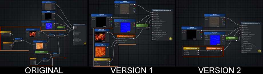
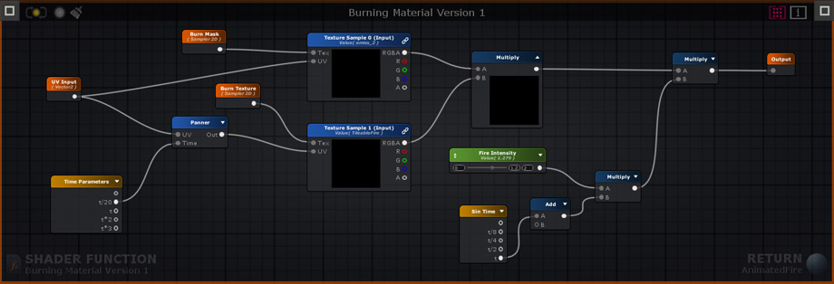
The node networks above all produce the same burning effect. The original version does not use shader functions. Version 1 uses a SF that contains the original node network used to generate the burning effect, it receives 1 Texture Object node for the burn mask, 1 Texture Object node for the fire texture, and 1 Texture Coordinate node. Version 2 is simpler than the previous example, the burn effect generation and texture nodes are all included in the SF, the only exception being the Texture Coordinate node that allows users to tweak its behavior. Keep in mind that a SF does not need to receive any input, the outputted data can be entirely generated in its graph if necessary. 上述节点网络都产生相同的燃烧效应。原始版本不使用着色函数。版本1使用一个包含用于生成燃烧效果的原始节点网络的SF,它接收1个纹理对象节点用于燃烧掩码,1个纹理对象节点用于燃烧纹理,1个纹理坐标节点。版本2比上一个例子简单,烧伤效果生成和纹理节点都包含在SF中,唯一的例外是纹理坐标节点,允许用户调整其行为。请记住,SF不需要接收任何输入,如果需要,可以在其图形中完全生成输出数据。 Version 1 Shader Function Example
Creation and Usage创建和使用
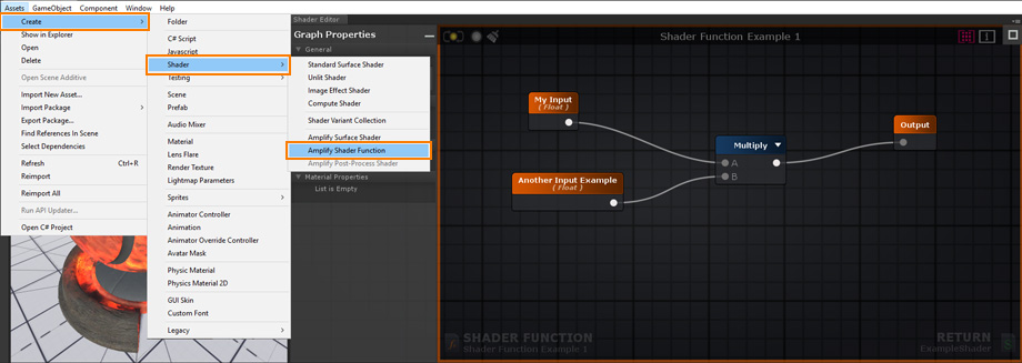
Create a new Shader Function Asset under Assets > Create > Shaders > Amplify Shader Function. 创建一个新的着色器函数资源,在菜单项 Assets > Create > Shaders > Amplify Shader Function.
Your newly created Shader Function will be automatically opened in the ASE Editor after being renamed. 您新创建的着色器函数将在被重命名后自动在ASE编辑器中打开。
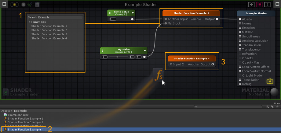
1. Add your Shader Function description here. You can also reorder your Function Inputs/Outputs and Material Properties by dragging them to the desired position. The order set in your SF will be the same used in your Material inspector tab. 1. 在这里添加着色器函数描述。您还可以通过将功能输入/输出和材料属性拖动到所需位置来重新排序。在你的SF中设置的订单将在你的材质检视标签中使用相同。 2. Create 2 Input nodes or more. By default, there's always 1 Output node but you can add as many as necessary. You can also use other SF nodes inside your active SF but, in order to avoid Shader Function Loops, you cannot add a function to its own canvas. 2. 创建两个或更多的输入节点。默认情况下,总是有一个输出节点,但是您可以添加任意多的输出节点。您还可以在活动的SF中使用其他SF节点,但是,为了避免Shader函数循环,您不能将函数添加到它自己的画布中。 3. Select an Input node to set the type used or toggle the Auto Cast option to automate the procedure directly in the left tab as you would with any other node properties. 3.选择一个输入节点来设置所使用的类型,或者像使用其他节点属性一样,在左侧选项卡中切换Auto Cast选项来直接自动化过程。 4. Connect your resulting output(s) directly to the Output node(s). 4. 将结果输出直接连接到输出节点。 5. Save your changes and click Return to go back to the previously open Shader or Material, if any. 5. 保存您的更改,并单击Return返回以前打开的着色器或材质(如果有的话)。
1. Add the created Shader Function to your shader by selecting it directly from the Node List. SF nodes can be used just as any other ASE nodes, they can be duplicated, copied, or deleted. 1. 通过直接从节点列表中选择创建的着色器函数添加到着色器。SF节点可以像任何其他ASE节点一样使用,它们可以被重复、复制或删除。 2. Alternatively, you can drag & drop Shader Functions directly into your editor canvas. 2. 或者,你可以直接拖拽着色器函数到你的编辑器画布。 3. Double-click a SF node to open it. 3.双击一个SF节点以打开它。 Hotkeys快捷键Colored Line Mode颜色的线模式
Press [ W ] to toggle it. 按[W]切换。 Node Previews节点预览
Press [ P ] to toggle node previews 按[P]切换节点预览 Multi-line Mode多行模式
Press [ CTRL + W ] to activate the multi-line mode. 按[CTRL + W]激活多行模式。 Full Shortcut List全部快捷键列表Editor 编辑器
Nodes 节点
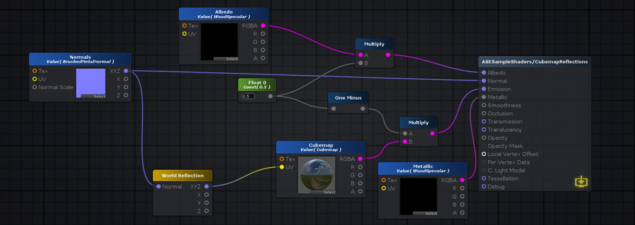
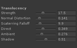
Translucency半透明The Translucency input provides a fast method of representing light scattering. It's not the most realistic method available but it's a flexible and fast-performing approximation. In our example (AmplifyShaderEditor\Examples\Official\Translucency) we use a simple red tinted Depth Texture to represent the skin subsurface scatter effect but you don't necessarily need to use the same setup, you could very well plug a full RGB texture to the Translucency Input in order to get some color variation or stylized results. 半透明输入提供了一种表示光散射的快速方法。这不是最现实的方法,但它是一个灵活和快速执行的近似。在我们的例子中(AmplifyShaderEditor \ \ \半透明)官方例子我们使用一个简单的红色着色深度纹理代表皮肤地下散射效应但你不一定需要使用相同的设置,你可以很好地填补完整RGB纹理半透明输入为了得到一些颜色变化或程式化的结果。
Your First shader你的第一个着色器
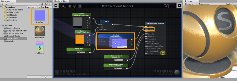
1. Open the Editor, create a new material and a new shader in the Project Explorer tab. In the newly created material, select your new shader and click on the Open in Shader Editor button to open both the shader and material. 1. 打开编辑器,在Project Explorer选项卡中创建一个新的材质和一个新的着色器。在新创建的材质中,选择你的新材质,点击Open In shader Editor按钮来打开着色器和材质。
2. As an example, select the Output Node and change its Light Model to specular. 2. 例如,选择输出节点并将其光照模型更改为高光。
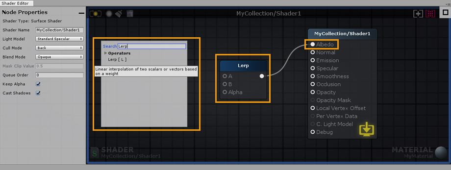
3. Right click on the canvas to open the searchable node list and type “Lerp”. Click on Lerp and connect the node Output Port to the Albedo Input Port. 3.右键单击画布,打开可搜索节点列表,输入“Lerp”。单击Lerp并将节点输出端口连接到反射率输入端口。
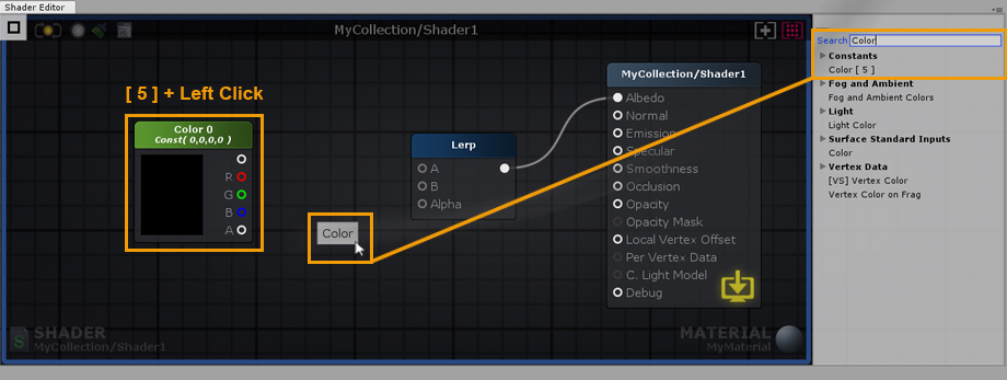
4. Hold the 5 shortcut key and click on the canvas to create a new Color node. Alternatively, you can use the searchable list used early or drag and drop the node from the Node Palette on the right side; Constants > Color [ 5 ]. 4. 按住5快捷键并单击画布创建一个新的Color节点。或者,您可以使用早期使用的可搜索列表,或者从右侧的节点调色板拖放节点;常数>颜色[5]。
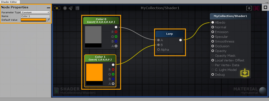
5. Select the new Color node and hit ‘CTRL/CMD+D’ to duplicate it. Connect both nodes to the Lerp Input Ports. Set the first node to gray and the second one to a more lively color. 5. 选择新的颜色节点并按CTRL/CMD+D复制它。将两个节点连接到Lerp输入端口。将第一个节点设置为灰色,将第二个节点设置为更生动的颜色。
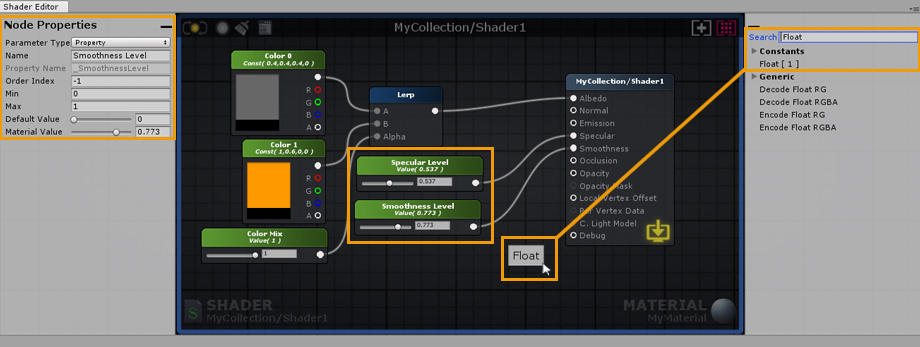
6. Create a Float node by dragging and dropping it from the Node Palette, connect it to the Alpha port of the Lerp node. In the node properties of the newly created float, set its Minimum value to 0 and Maximum to 1. Notice that the Float can now be controlled by a Slider. Don’t forget to set its Parameter Type to Property, this way you will be able to change it directly in the material. You can also name the node and change its position in the material inspector by adjusting the Index value. As an example, lets name it Color Mix. 6. 通过从节点面板中拖放浮动节点创建浮动节点,将其连接到Lerp节点的Alpha端口。在新创建的浮点数的节点属性中,将其最小值设置为0,最大值设置为1。注意,浮动现在可以由滑块控制。不要忘记将其参数类型设置为Property,这样您就可以在材质中直接更改它。您还可以通过调整索引值来命名节点并更改其在材料检查器中的位置。例如,让我们命名它为Color Mix。
7. Create a new Float and connect it to the Smoothness Input Port of the Output Node, set its Minimum value to 0 and Maximum to 1 as you did before. Set its type to Property and name it Smoothness Value. Create another Float and connect it to the Specular Input Port, set its Minimum value to 0 and Maximum to 1. Set its Type to Property and name it Specular Value. 7. 创建一个新的浮动,并将其连接到输出节点的平滑输入端口,将其最小值设置为0,最大值设置为1,就像您之前所做的那样。将其类型设置为属性,并将其命名为平滑度值。创建另一个浮动并将其连接到镜面输入端口,将其最小值设置为0,最大值设置为1。将其类型设置为属性并将其命名为高光值。
8. To conclude, Drag and Drop a Normal Map texture from your Project Explorer directly into the canvas. As an example, we used a Brushed Metal texture. Connect it to the Normal Input Port of the Output Node and you are done. You have just built your first shader, don’t forget to save your work regularly by clicking the Update button located in the upper left corner. Alternatively, you could edit the shader with the LIVE mode enabled, any change are immediately saved and updated. Depending on the complexity of the shader, the LIVE mode may take a second or so to update. Contrary to Default shader values, any changes made to a material property are immediately visible. 8. 最后,将一个普通的地图纹理从Project Explorer中直接拖放到画布中。例如,我们使用了拉丝金属纹理。将它连接到输出节点的正常输入端口,就完成了。你刚刚建立了你的第一个着色器,不要忘记通过点击左上角的更新按钮来定期保存你的工作。或者,你可以在启用实时模式的情况下编辑着色器,任何更改都会立即保存和更新。根据着色器的复杂性,实时模式可能需要一秒钟左右的时间来更新。与默认着色器值相反,对材质属性所做的任何更改都是立即可见的。
|


3rd-Party Compatibility
第三方的兼容性
Substance Support
Support for Substances in Unity 2018 and above has been added to ASE.
The original Substance example had to be packaged into a Unity package since .sbsar files now cause an importing error in Unity 2018, as native Substance support has been dropped.
原来的物质例子必须被打包成一个Unity包,因为。sbsar文件现在导致一个导入错误在Unity 2018,因为原生实例化支持已经被删除。
If you're using pre-Unity 2018 versions where native Substance support wasn't yet deprecated, you can find the Substance Example below:
如果你使用的是2018年版的pre-Unity,在这个版本中,原生实例化的支持还没有被弃用,你可以找到下面的物质例子:
- Go into the AmplifyShaderEditor\Examples\Official\Substance folder
- 进入AmplifyShaderEditor\ example \Official\Substance文件夹
- Extract the LegacySubstanceExample.unitypackage
- 提取LegacySubstanceExample.unitypackage
If you're using Unity 2018, you'll need to make sure that you install the Allegorithmic Substance plugin before you extract the proper ASE package:
如果你使用Unity 2018,你需要确保在提取合适的ASE包之前安装了mic Substance插件:
- Download, import and setup the Substance in Unity
- 在Unity中下载、导入和设置实例化
- Go into the AmplifyShaderEditor\Examples\Official\Substance2018 folder
- 进入AmplifyShaderEditor\ example \Official\Substance2018文件夹
- Extract the Substance2018.unitypackage
- 提取Substance2018.unitypackage
ASE lets you use substances directly or indirectly from within the editor. The most basic way to use a substance is to literally drag and drop a substance asset inside the editor. A new Substance Sample node will be created with it's various textures inside that can be used anywhere.
ASE允许您直接或间接地从编辑器中使用实例化。使用实体最基本的方法是在编辑器中真正地拖放实体资源。一个新的实例化样本节点将创建它的各种纹理可以在任何地方使用。
It's possible to set the substance to generate all textures and drag and drop each one of them independently as a regular texture. These will maintain their reference and update accordingly even if you regenerate the textures.
可以设置实体来生成所有纹理,并将它们作为常规纹理分别拖放。即使你重新生成纹理,它们也会保持它们的引用并相应地更新。
It's also possible to create a generic shader that is used directly in the shader. The only caveat for this is the extra configuration needed in the substance asset to link each texture sample to a generated texture. If a more automatic process is needed the texture sample node can be set to use a property name that matches Unity's default names (ie: _MainTex for albedos, _SpecGlossMap for specular maps, _MetallicGlossMap for metallic maps, _Glossiness for smoothness maps, _BumpMap for normal maps, _OcclusionMap for occlusion maps, _EmissionMap for emission maps, etc) This way the substance asset will detect the property and automatically assign them the correct texture without extra intervention.
也可以创建一个直接在着色器中使用的通用着色器。唯一需要注意的是,实体资源中需要额外的配置来将每个纹理样本链接到生成的纹理。如果需要更多的自动过程纹理样本节点可以设置为使用一个统一的默认名称匹配的属性名(即:_MainTex反射率,_SpecGlossMap镜面光泽度贴图,_MetallicGlossMap对金属光泽贴图,_Glossiness光泽贴图,_BumpMap法线贴图,_OcclusionMap遮挡贴图,_EmissionMap自发光贴图,等等)这样的实例化资源将自动检测属性和分配正确的纹理没有额外的干预。
MegaSplat
Native support for ASE is included in MegaSplat
Curved World Shaders
弯曲的世界着色器
This guide will show you how to integrate Curved World with the Amplify Shader Editor.
You may download a simple example here.
本指南将向你展示如何与Amplify Shader编辑器集成曲面世界。
您可以在这里下载一个简单的示例。

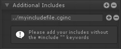
1. For the first step, we're going to include the curvedworld.cginc file. In the image above, notice how we added the include with the string: "../cginc/CurvedWorld_Base.cginc", this is because our shader file was in a folder next to the cginc folder where the file is, so the "../" part of the string goes up one folder, the "/cginc/" part looks inside the cginc folder and the last part is the file itself. You could simply use "CurvedWorld_Base.cginc" IF your shader file was next to this file.
1. 第一步,我们将包括曲线世界。cginc文件。在上面的图像中,注意我们是如何用字符串“../cginc/CurvedWorld_Base”添加include的。这是因为我们的着色器文件在文件所在的cginc文件夹旁边的一个文件夹中,所以…/"字符串的一部分进入一个文件夹,"/cginc/"部分进入cginc文件夹,最后一部分是文件本身。您可以简单地使用“CurvedWorld_Base”。如果你的着色器文件在这个文件的旁边。
Note: You have to be careful with this inclusion because Unity doesn't let you automatically detect where the file is by name, you have to specify the file path. If you happen to move the file to a different folder you have to fix the file path and recompile the shader again or else it will fail to include the file.
注意:您必须小心这个包含,因为Unity不允许您根据名称自动检测文件的位置,您必须指定文件路径。如果您碰巧将文件移动到另一个文件夹,您必须修复文件路径并重新编译着色器,否则它将无法包含该文件。

2. Secondly, in order to apply the curved world effect to the object with your shader, you need to call its own Function, which is within the file we included in the first step. To achieve this, you must create and connect a custom expression node into the "local vertex offset" output and have it call the Function you want to call in the code box, which in this case is "V_CW_TransformPointAndNormal(v.vertex, v.normal,v.tangent);". Notice the "Call Mode" checkbox in the parameters panel, it needs to be toggled on in order for this step to work without any issues.
2. 其次,为了在你的着色器中应用曲面世界效果,你需要调用它自己的函数,它在我们在第一步中包含的文件中。要实现这一点,您必须创建一个自定义表达式节点并将其连接到“局部顶点偏移量”输出,并让它调用您想要在代码框中调用的函数,在本例中是“V_CW_TransformPointAndNormal(v)”。顶点,v.normal v.tangent);”。请注意parameters面板中的“Call Mode”复选框,需要打开它才能使此步骤正常工作,没有任何问题。
Note: Should you need to do some vertex transformation, you can still connect it to the input of the Function node.
注意:如果需要进行一些顶点变换,仍然可以将其连接到函数节点的输入端。
That's it! Now you can use everything else like you would in a normal ASE shader and it should work in curved world!
就是这样!现在你可以像在普通的ASE着色器中一样使用其他任何东西,它应该在弯曲的世界中工作!
VertExmotion
The VertExmotion package includes built-in nodes for ASE.
1.Unpack the file 'VertExmotion/Addon/VertExmotion_AmplifyShaderEditorNodes.unitypackage'.
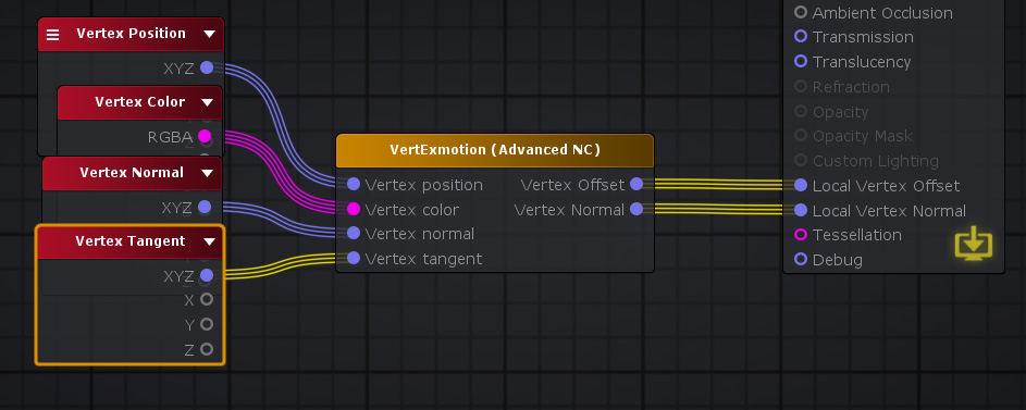
2. Add the VertExmotion node and connect it to the Local Vertex Offset Input port.

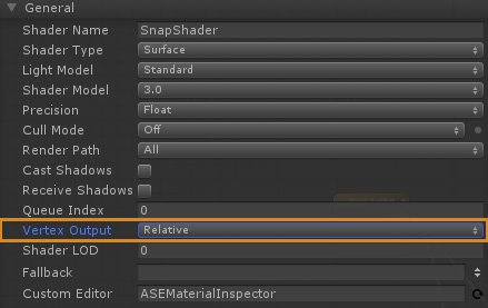
3. Set the Vertex Output to 'Relative' in the Output Node parameters.
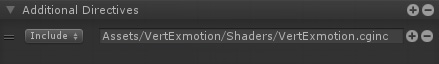
4. Add the VertExmotion cginc file (Assets/VertExmotion/Shaders/VertExmotion.cginc) under Additional Directives, Includes.
5. If you're using tessellation, be sure to add the VertExmotion (Advanced NC) node; plug both the Vertex Offset and Normal to the Output Node inputs. (Optional)
6. HD SRP variant included. (Optional)

General Tips
一般建议
Mobile Shaders
移动平台着色器
When creating shaders for mobile there are some special considerations to take into account. Usually these considerations are tied to the performance of the shader but sometimes there are artistic or design choices that lead to modifications that are needed at the shader level.
在为移动设备创建着色器时,需要考虑一些特殊的因素。通常这些考虑是与着色器的性能联系在一起的,但有时有艺术或设计的选择,导致需要在着色器级别的修改。
These are just the most common way you may find useful to create shaders for mobile:
这些只是最常见的方法,你可能会发现有用的创建着色移动:
Rendering Options
渲染选项
Often overlooked, rendering options let you turn off some key feature of unity lighting system. For example, you may find to be enough for your purpose to turn off Unity GI system but still maintaining their PBR workflow.
经常被忽略的是,渲染选项可以让你关闭unity照明系统的一些关键功能。例如,您可能会发现,对于您的目的来说,关闭Unity GI系统已经足够了,但是仍然需要维护它们的PBR工作流。
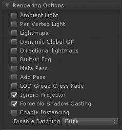
It this image extreme example every special lighting feature is turned off and even shadows are off. This might not be what what's needed, but it's a good starting point.
这是一个极端的例子,每个特殊的照明功能都被关闭,甚至阴影也被关闭。这可能不是我们需要的,但这是一个很好的起点。
Custom Lighting Model
自定义光照模型
ASE allows the creation of custom lighting model shaders. These are still unity surface shaders that allow the replacement of unity lighting functions. In ASE this means you can set your shader Light Model into custom lighting. Doing this will transform the main output node into one that only has emission and opacity ports. With this it's possible to use existing nodes with some extra light nodes to create an optimized and tailor fitted shader for a specific purpose.
ASE允许创建定制的照明模型着色器。这些仍然是统一的表面着色器,允许替换统一照明功能。在ASE中,这意味着你可以将你的着色器灯光模型设置为自定义光照。这样做将把主输出节点转换为只有自发光和不透明度端口的节点。有了这个,就有可能使用现有的节点和一些额外的光照节点来创建一个优化和适合特定用途的着色器。
The following image shows how it's possible to create a simple wrapped Lambertian shader which should be very performant for lower end machines.
下面的图片展示了如何创建一个简单的封装Lambertian着色器,这应该是非常性能的低端机器。 Nodes used: Texture Sample, World Normal, World Space Light Dir, Dot, Multiply Float, Add
Combine this with the previous rendering options for extra savings and do notice how in the general options a few of them where turned off or down for better performance (ie: Shader Model, Precision, Cast Shadows)
将这个与之前的渲染选项结合起来,可以节省额外的开销,请注意在常规选项中,为了获得更好的性能,其中一些选项是关闭或关闭的(例如:着色器模型、精度、投影阴影)
As a learning step, it might be a good idea to check the Toon Ramp sample provided by the ASE package which uses custom lighting in a more complex way to create a toon ramp effect with rim light and shadow support.
作为一个学习步骤,检查ASE包提供的Toon Ramp样品可能是一个好主意,它使用更复杂的自定义光照来创建带有边缘光和阴影支持的Toon Ramp效果。
Mobile Friendly Templates
移动平台好用的模板
Some times what's needed is a specific vertex/frag shader that does a very simple job, for instance, particles, sprites, UI, etc. For these cases and others ASE allows the injection of shader code into pre-existing shaders that we call "templates". These are regular vertex/frag shaders that were modified by adding some tags the editor can read to know where to inject new code and what code already exists in the template.
有时需要的是一个特定的顶点/片段着色器,它做一个非常简单的工作,例如,粒子,精灵,UI等。对于这些情况和其他ASE允许注入着色器代码到预先存在的着色器,我们称之为“模板”。这些是常规的顶点/片段着色器,通过添加一些标签,编辑器可以读取这些标签,从而知道在哪里注入新代码,以及模板中已经存在哪些代码。
There's a whole page dedicated on how these templates work and how you can build your own right here.
有一整个页面专门介绍这些模板如何工作,以及如何在这里构建自己的模板。
The reason they might be important for mobile shaders is that these templates can be extremely simple with barely any code at all. If the idea is to save performance, a generic unlit template can serve as a base to build upon since these are editable inside the editor and extra features can be added either by construction a more complex graph tree or by editing the original template. The only caveat being the user must have a bit of shader knowledge to edit or create the original template shader. Fortunately ASE already provides a few templates that any user can pick and use as any other shader.
它们对移动着色器很重要的原因是这些模板非常简单,几乎不需要任何代码。如果这样做是为了节省性能,那么一般的未点亮模板可以作为构建的基础,因为这些模板在编辑器中是可编辑的,可以通过构造更复杂的图形树或编辑原始模板来添加额外的功能。唯一的警告是,用户必须有一点着色知识来编辑或创建原始模板着色器。幸运的是,ASE已经提供了一些模板,任何用户都可以选择和使用作为任何其他着色器。
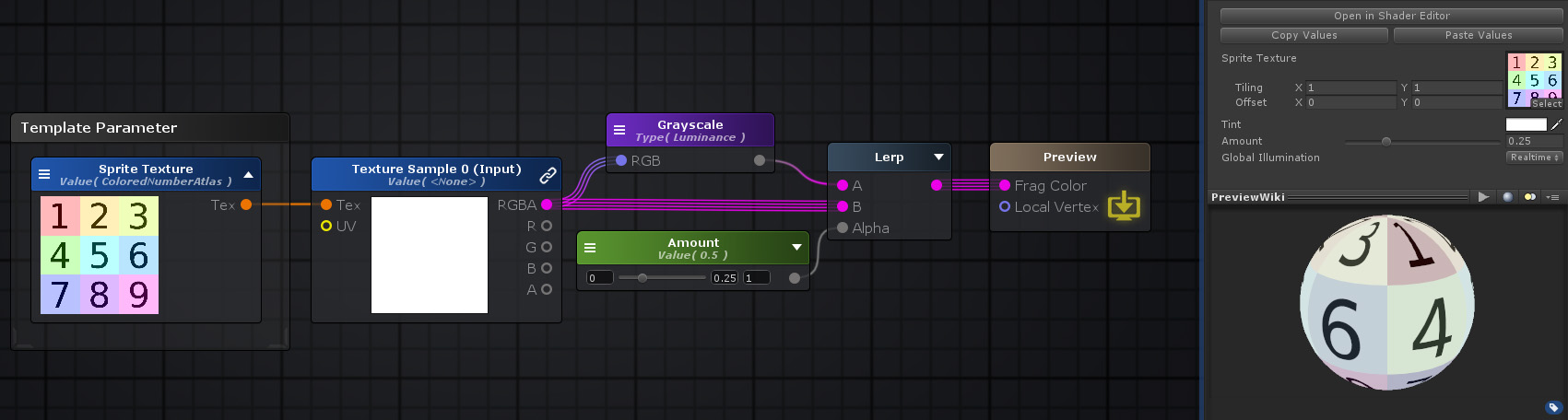 Nodes used: Template Parameter, Texture Sample, Grayscale, Float, Lerp
This feature is still in development and more of these templates will be provided in the future to implement more complex or specific effects when they become available.
该特性仍在开发中,将来将提供更多的模板,以便在可用时实现更复杂或特定的效果。
Android
When using the Texture Sampler node in ASE and the target platform is Android, it will ignore the Scale Parameter, which is an intended behaviour because Unity does not scale normal maps for platforms that don't support DXT5nm format, which is the format Unity compresses normal maps into.
在ASE中使用纹理采样器节点,目标平台为Android时,忽略尺度参数,这是一种有意的行为,因为Unity对于不支持DXT5nm格式的平台不缩放法线贴图,而DXT5nm格式是Unity压缩法线贴图的格式。
Although this can be fixed by directly changing the built-in shader files, which is troublesome to do and to maintain, a simpler solution would be to do the exact same calculation that Unity does withing the editor itself.
虽然这可以通过直接更改内置的着色器文件来修复,但是这样做和维护起来很麻烦,一个更简单的解决方案是使用Unity在编辑器本身上所做的完全相同的计算。
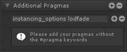
The following image and shader file perform this calculation while also making sure that the shader still works even outside of the Android environment by checking the define symbol that Unity sets itself. We recommend that you create a Shader Function with this logic if you need to use it in several shaders.
下面的图像和着色器文件执行了这个计算,同时通过检查Unity设置自己的define符号,确保着色器仍然可以在Android环境之外工作。如果需要在多个着色器中使用该逻辑,我们建议您使用该逻辑创建一个着色器函数。


 3万+
3万+

 被折叠的 条评论
为什么被折叠?
被折叠的 条评论
为什么被折叠?
 到【灌水乐园】发言


