


 本教程深入浅出地讲解了Verilog HDL的基础概念与高级特性,包括基本逻辑门设计、向量操作、模块层次结构、过程块及Verilog的其他特性。通过丰富的实例练习帮助读者掌握Verilog语法。
Verilog刷题记录01
仅作为下面学习网站的参考解答,详细语法介绍请参考另一篇博客 Verilog永无止境。
一、basics
1. simple wire
   module top_module( input in, output out );
   	assign out = in;
   endmodule
2. inverter:
Verilog has separate bitwise-NOT (~) and logical-NOT (!) operators, like C. Since we’re working with a one-bit here, it doesn’t matter which we choose.
   ```verilog
   module top_module(
   	input in,
   	output out
   );

   	assign out = ~in;

   endmodule
3. AND gate
Verilog has separate bitwise-AND (&) and logical-AND (&&) operators, like C. Since we’re working with a one-bit here, it doesn’t matter which we choose.
   ```verilog
   module top_module(
       input a,
       input b,
       output out );
   	assign out = a&b;
   endmodule
4. Nor gate(或非门)
   ```verilog
   module top_module(
       input a,
       input b,
       output out );
       assign out = ~(a|b);
   endmodule
5. XNOR gate(同或门)
   ```verilog
   module top_module(
       input a,
       input b,
       output out );
       assign out = ~(a^b);
   endmodule
6. declaring wire

   ```verilog
   `default_nettype none
   module top_module(
       input a,
       input b,
       input c,
       input d,
       output out,
       output out_n   );

       wire and_1,and_2,or_1;
       assign and_1 = a&b;
       assign and_2 = c&d;
       assign or_1 = and_1|and_2;

       assign out = or_1;
       assign out_n = ~or_1;
   endmodule
7. 7458 chip

```verilog
module top_module (
    input p1a, p1b, p1c, p1d, p1e, p1f,
    output p1y,
    input p2a, p2b, p2c, p2d,
    output p2y );

    wire p2y_1,p2y_2;
    assign p2y_1 = p2a&p2b;
    assign p2y_2 = p2c&p2d;
    assign p2y = p2y_1 | p2y_2;

    wire p1y_1,p1y_2;
    assign p1y_1 = p1a&p1b&p1c;
    assign p1y_2 = p1d&p1e&p1f;
    assign p1y = p1y_1 | p1y_2;


endmodule
二、vectors
1. Vector0

   ```verilog
   module top_module (
       input wire [2:0] vec,
       output wire [2:0] outv,
       output wire o2,
       output wire o1,
       output wire o0  ); // Module body starts after module declaration

       assign outv[2:0] = vec[2:0];
       assign o0 = vec[0];
       assign o1 = vec[1];
       assign o2 = vec[2];

   endmodule
2. Vector 1
Vectors must be declared:
   ```verilog
   type [upper:lower] vector_name;

   //for example:
   wire [7:0] w;         // 8-bit wire
   reg  [4:1] x;         // 4-bit reg
   output reg [0:0] y;   // 1-bit reg that is also an output port (this is still a vector)
   input wire [3:-2] z;  // 6-bit wire input (negative ranges are allowed)
   output [3:0] a;       // 4-bit output wire. Type is 'wire' unless specified otherwise.
   wire [0:7] b;         // 8-bit wire where b[0] is the most-significant bit.
   ```verilog
   wire [2:0] a, c;    // Two vectors
   assign a = 3'b101;  // a = 101
   assign b = a;       // b =   1  implicitly-created wire
   assign c = b;       // c = 001  <-- bug
   my_module i1 (d,e); // d and e are implicitly one-bit wide if not declared.                    			  // This could be a bug if the port was intended to be a vector.
Adding ``default_nettype none` would make the second line of code an error, which makes the bug more visible.
   ```verilog
   assign w = a;
takes the entire 4-bit vector a and assigns it to the entire 8-bit vector w (declarations are taken from above). If the lengths of the right and left sides don’t match, it is zero-extended or truncated as appropriate.
  ```verilog
   The part-select operator can be used to access a portion of a vector:

   w[3:0]      // Only the lower 4 bits of w
   x[1]        // The lowest bit of x
   x[1:1]      // ...also the lowest bit of x
   z[-1:-2]    // Two lowest bits of z
   b[3:0]      // Illegal. Vector part-select must match the direction of the declaration.
   b[0:3]      // The *upper* 4 bits of b.
   assign w[3:0] = b[0:3];    // Assign upper 4 bits of b to lower 4 bits of w. w[3]=b[0], w[2]=b[1], etc.
-
Practice:
- Build a combinational circuit that splits an input half-word (16 bits, [15:0] ) into lower [7:0] and upper [15:8] bytes.
 ```verilog
  `default_nettype none     // Disable implicit nets. Reduces some types of bugs.
  module top_module(
   input wire [15:0] in,
   output wire [7:0] out_hi,
   output wire [7:0] out_lo );

   assign out_hi = in[15:8];
   assign out_lo = in[7:0];
 endmodule
3. Vector 2
Practice:
- A 32-bit vector can be viewed as containing 4 bytes (bits [31:24], [23:16], etc.). Build a circuit that will reverse the byte ordering of the 4-byte word.
 ```verilog
 module top_module(
     input [31:0] in,
     output [31:0] out);

     assign out[31:24] = in[7:0];
     assign out[23:16] = in[15:8];
     assign out[15:8] = in[23:16];
     assign out[7:0] = in[31:24];
 endmodule
4. vectorgates
Bitwise vs. Logical Operators
A bitwise operation between two N-bit vectors replicates the operation for each bit of the vector and produces a N-bit output, while a logical operation treats the entire vector as a boolean value (true = non-zero, false = zero) and produces a 1-bit output.
   ```verilog
   module top_module(
   	input [2:0] a,
   	input [2:0] b,
   	output [2:0] out_or_bitwise,
   	output out_or_logical,
   	output [5:0] out_not
   );

   	assign out_or_bitwise = a | b;
   	assign out_or_logical = a || b;

   	assign out_not[2:0] = ~a;	// Part-select on left side is o.
   	assign out_not[5:3] = ~b;	//Assigning to [5:3] does not conflict with [2:0]

   endmodule
5. Four-input gates
Build a combinational circuit with four inputs, in[3:0].
There are 3 outputs:
- out_and: output of a 4-input AND gate.
- out_or: output of a 4-input OR gate.
- out_xor: output of a 4-input XOR gate.
   ```verilog
   module top_module(
       input [3:0] in,
       output out_and,
       output out_or,
       output out_xor
   );
       assign out_and = in[0]&in[1]&in[2]&in[3];
       assign out_or = in[0]|in[1]|in[2]|in[3];
       assign out_xor = in[0]^in[1]^in[2]^in[3];

   endmodule
6. Vector3
Part selection was used to select portions of a vector. The concatenation operator {a,b,c} is used to create larger vectors by concatenating smaller portions of a vector together.
   {3'b111, 3'b000} => 6'b111000
   {1'b1, 1'b0, 3'b101} => 5'b10101
   {4'ha, 4'd10} => 8'b10101010     // 4'ha and 4'd10 are both 4'b1010 in binary
   ```verilog
   input [15:0] in;
   output [23:0] out;
   assign {out[7:0], out[15:8]} = in;         // Swap two bytes. Right side and left side are both 16-bit vectors.
   assign out[15:0] = {in[7:0], in[15:8]};    // This is the same thing.
   assign out = {in[7:0], in[15:8]};       // This is different. The 16-bit vector on the right is extended to
                                           // match the 24-bit vector on the left, so out[23:16] are zero.
                                           // In the first two examples, out[23:16] are not assigned.
A Bit of Practice

   ```verilog
   module top_module (
       input [4:0] a, b, c, d, e, f,
       output [7:0] w, x, y, z );//

       assign { w,x,y,z } = { a,b,c,d,e,f,2'b11 };

   endmodule
7. vecorr
- Given an 8-bit input vector [7:0], reverse its bit ordering.
   ```verilog
   module top_module(
       input [7:0] in,
       output [7:0] out
   );
       assign {out[7],out[6],out[5],out[4],out[3],out[2],out[1],out[0]} = in;
       /*using loop*/
       /*always @(*) begin
   		for (int i=0; i<8; i++)	// int is a SystemVerilog type. Use integer for pure Verilog.
   			out[i] = in[8-i-1];
   	end*/

   endmodule
8. Vector4
The concatenation operator allowed concatenating together vectors to form a larger vector. But sometimes you want the same thing concatenated together many times, and it is still tedious to do something like assign a = {b,b,b,b,b,b};. The replication operator allows repeating a vector and concatenating them together:
   ```verilog
   {num{vector}}
   ```verilog
   {5{1'b1}}           // 5'b11111 (or 5'd31 or 5'h1f)
   {2{a,b,c}}          // The same as {a,b,c,a,b,c}
   {3'd5, {2{3'd6}}}   // 9'b101_110_110. It's a concatenation of 101 with
                       // the second vector, which is two copies of 3'b110.
A Bit of Practice
- Build a circuit that sign-extends an 8-bit number to 32 bits. This requires a concatenation of 24 copies of the sign bit (i.e., replicate bit[7] 24 times) followed by the 8-bit number itself.
   ```verilog
   module top_module (
       input [7:0] in,
       output [31:0] out );//

       assign out = { {24{in[7]}},in };

   endmodule
9. vector5
   ```verilog
   module top_module (
       input a, b, c, d, e,
       output [24:0] out );//

       // The output is XNOR of two vectors created by
       // concatenating and replicating the five inputs.
       assign out = ~{ {5{a}},{5{b}},{5{c}},{5{d}},{5{e}} } ^ { 5{a,b,c,d,e} };

   endmodule
三、Modules:Hierarchy
1. module
There are two commonly-used methods to connect a wire to a port: by position or by name.
The syntax to connect wires to ports by position should be familiar, as it uses a C-like syntax. When instantiating a module, ports are connected left to right according to the module’s declaration. For example:
mod_a instance1 ( wa, wb, wc );//instance is a key word, don't use it to name a module.
Connecting signals to a module’s ports by name allows wires to remain correctly connected even if the port list changes. This syntax is more verbose, however.
```verilog
mod_a instance2 ( .out(wc), .in1(wa), .in2(wb) );
The above line instantiates a module of type mod_a named “instance2”, then connects signal wa (outside the module) to the port named in1, wb to the port named in2, and wc to the port named out. Notice how the ordering of ports is irrelevant here because the connection will be made to the correct name, regardless of its position in the sub-module’s port list.
```verilog
module top_module (
	input a,
	input b,
	output out
);

	// Create an instance of "mod_a" named "inst1", and connect ports by name:
	mod_a inst1 (
		.in1(a), 	// Port"in1"connects to wire "a"
		.in2(b),	// Port "in2" connects to wire "b"
		.out(out)	// Port "out" connects to wire "out"
				// (Note: mod_a's port "out" is not related to top_module's wire "out".
				// It is simply coincidence that they have the same name)
	);

/*
	// Create an instance of "mod_a" named "inst2", and connect ports by position:
	mod_a inst2 ( a, b, out );	// The three wires are connected to ports in1, in2, and out, respectively.
*/

endmodule
2. Module pos
```verilog
module top_module (
    input a,
    input b,
    input c,
    input d,
    output out1,
    output out2
);
    mod_a inst (out1,out2,a,b,c,d);
endmodule
3. Module name
```verilog
module top_module (
    input a,
    input b,
    input c,
    input d,
    output out1,
    output out2
);
mod_a inst (.out1(out1),.out2(out2),.in1(a),.in2(b),.in3(c),.in4(d));

endmodule
4. Module shift
```verilog
module top_module ( input clk, input d, output q );
	wire q1,q2;// Create two wires. I called them q1 and q2.
	my_dff inst1 (clk,d,q1);
    my_dff inst2 (clk,q1,q2);
    my_dff inst3 (clk,q2,q);

endmodule
5. Module shift8

```verilog
module top_module (
	input clk,
	input [7:0] d,
	input [1:0] sel,
	output reg [7:0] q
);

	wire [7:0] o1, o2, o3;		// output of each my_dff8

	// Instantiate three my_dff8s
	my_dff8 d1 ( clk, d, o1 );
	my_dff8 d2 ( clk, o1, o2 );
	my_dff8 d3 ( clk, o2, o3 );

	// This is one way to make a 4-to-1 multiplexer
	always @(*)		// Combinational always block
		case(sel)
			2'h0: q = d;
			2'h1: q = o1;
			2'h2: q = o2;
			2'h3: q = o3;
		endcase

endmodule
6. Module add
```verilog
module top_module(
    input [31:0] a,
    input [31:0] b,
    output [31:0] sum
);
    wire cout,x;
    add16 inst1 (a[15:0],b[15:0],1'b0,sum[15:0],cout);
    add16 inst2 (a[31:16],b[31:16],cout,sum[31:16],x);
endmodule
7. Module fadd
Connect the add16 modules together as shown in the diagram below. The provided module add16 has the following declaration:
module add16 ( input[15:0] a, input[15:0] b, input cin, output[15:0] sum, output cout );
Within each add16, 16 full adders (module add1, not provided) are instantiated to actually perform the addition. You must write the full adder module that has the following declaration:
module add1 ( input a, input b, input cin, output sum, output cout );
Recall that a full adder computes the sum and carry-out of a+b+cin.
module top_module (
    input [31:0] a,
    input [31:0] b,
    output [31:0] sum
);//
    wire x,cout;
    add16 inst1 (a[15:0],b[15:0],1'b0,sum[15:0],cout);
    add16 inst2 (a[31:16],b[31:16],cout,sum[31:16],x);

endmodule

module add1 ( input a, input b, input cin,   output sum, output cout );
    assign sum = a^b^cin;
    assign cout = (a&b) | (a^b)&cin;
endmodule
8. Module cseladd
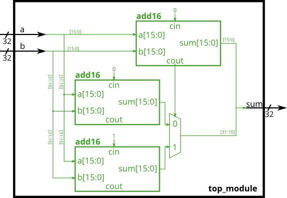
module top_module(
    input [31:0] a,
    input [31:0] b,
    output [31:0] sum
);
    wire x1,x2,cout;
    wire [31:0] tmp_sum1;
    wire [31:0] tmp_sum2;
    add16 inst1 (a[15:0],b[15:0],1'b0,sum[15:0],cout);

    add16 inst2 (a[31:16],b[31:16],1'b0,tmp_sum1[31:16],x1);
    add16 inst3 (a[31:16],b[31:16],1'b1,tmp_sum2[31:16],x2);

    assign sum[31:16] = (cout) ? tmp_sum2[31:16] : tmp_sum1[31:16];

endmodule
9. AddSub
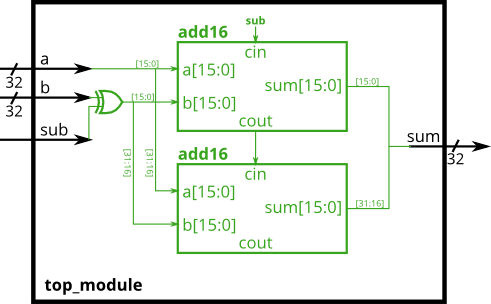
module top_module(
    input [31:0] a,
    input [31:0] b,
    input sub,
    output [31:0] sum
);
    wire [31:0] sig_b;//b or ~b
    assign sig_b = b^{32{sub}};//按位异或,要控制位数相同
    wire cout,x1;

    add16 inst1 (a[15:0],sig_b[15:0],sub,sum[15:0],cout);
    add16 inst2 (a[31:16],sig_b[31:16],cout,sum[31:16],x1);

endmodule
四、Procedures
1. Alwaysblock1
Procedures (of which always blocks are one example) provide an alternative syntax for describing circuits.
For synthesizing hardware, two types of always blocks are relevant:
- Combinational:
always @(*) - Clocked:
always @(posedge clk)
Procedural blocks have a richer set of statements (e.g., if-then, case), cannot contain continuous assignments*, but also introduces many new non-intuitive ways of making errors. Procedural continuous assignments are not synthesizable.
Build an AND gate using both an assign statement and a combinational always block. (assign statements and combinational always blocks function identically.)
// synthesis verilog_input_version verilog_2001
module top_module(
    input a,
    input b,
    output wire out_assign,
    output reg out_alwaysblock
);
    //在这里,两种结果相同,不过变量类型有限制,下面是reg
    assign out_assign = a&b;
    always @(*) out_alwaysblock = a&b;

endmodule
2. AlwaysBlock2
Blocking vs. Non-Blocking Assignment
There are three types of assignments in Verilog:
- Continuous assignments (
assign x = y;). Can only be used when not inside a procedure (“always block”). - Procedural blocking assignment: (
x = y;). Can only be used inside a procedure. - Procedural non-blocking assignment: (
x <= y;). Can only be used inside a procedure.
In a combinational always block, use blocking assignments. In a clocked always block, use non-blocking assignments.
A bit of practice
Build an XOR gate three ways, using an assign statement, a combinational always block, and a clocked always block. Note that the clocked always block produces a different circuit from the other two: There is a flip-flop so the output is delayed.
// synthesis verilog_input_version verilog_2001
module top_module(
    input clk,
    input a,
    input b,
    output wire out_assign,
    output reg out_always_comb,
    output reg out_always_ff   );
    assign out_assign = a^b;
    always @(*) out_always_comb = a^b;
    //延迟一个时钟周期
    always @(posedge clk) out_always_ff <= a^b;

endmodule
3. Always if
An if statement usually creates a 2-to-1 multiplexer, selecting one input if the condition is true, and the other input if the condition is false.

always @(*) begin
    if (condition) begin
        out = x;
    end
    else begin
        out = y;
    end
end
This is equivalent to using a continuous assignment with a conditional operator:
assign out = (condition) ? x : y;
| sel_b1 | sel_b2 | out_assign out_always |
|---|---|---|
| 0 | 0 | a |
| 0 | 1 | a |
| 0 | 0 | a |
| 1 | 1 | b |
// synthesis verilog_input_version verilog_2001
module top_module(
    input a,
    input b,
    input sel_b1,
    input sel_b2,
    output wire out_assign,
    output reg out_always   );
    assign out_assign = b&(sel_b1&sel_b2) | a&(~(sel_b1&sel_b2));
    always @(*) begin
        if(sel_b1&sel_b2) begin
            out_always = b;
        end
        else begin
            out_always = a;
    	end
    end

endmodule
4. Always if 2
When designing circuits, you must think first in terms of circuits:
- I want this logic gate
- I want a combinational blob of logic that has these inputs and produces these outputs
- I want a combinational blob of logic followed by a set of flip-flops
you always need else clauses or a default value assigned to the outputs.
always @(*) begin
    if (cpu_overheated)
       shut_off_computer = 1;
end

always @(*) begin
    if (~arrived)
       keep_driving = ~gas_tank_empty;
end
// synthesis verilog_input_version verilog_2001
module top_module (
    input      cpu_overheated,
    output reg shut_off_computer,
    input      arrived,
    input      gas_tank_empty,
    output reg keep_driving  ); //

    always @(*) begin
        if (cpu_overheated) begin
           shut_off_computer = 1;
        end
        else begin
            shut_off_computer = 0;
        end
    end

    always @(*) begin
        if (~arrived)
           keep_driving = ~gas_tank_empty;
        else
            keep_driving = 0;
    end

endmodule
5. Always case
always @(*) begin     // This is a combinational circuit
    case (in)
      1'b1: begin
               out = 1'b1;  // begin-end if >1 statement
            end
      1'b0: out = 1'b0;
      default: out = 1'bx;
    endcase
end
6. Always casez
This is what casez is for: It treats bits that have the value z as don’t-care in the comparison.
always @(*) begin
    casez (in[3:0])
        4'bzzz1: out = 0;   // in[3:1] can be anything
        4'bzz1z: out = 1;
        4'bz1zz: out = 2;
        4'b1zzz: out = 3;
        default: out = 0;
    endcase
end
// synthesis verilog_input_version verilog_2001
module top_module (
    input [7:0] in,
    output reg [2:0] pos  );
    always @(*) begin
        casez (in[7:0])
            8'b10000000: pos = 7;
            8'bz1000000: pos = 6;
            8'bzz100000: pos = 5;
            8'bzzz10000: pos = 4;
            8'bzzzz1000: pos = 3;
            8'bzzzzz100: pos = 2;
            8'bzzzzzz10: pos = 1;
            default: pos = 0;
        endcase
    end
endmodule
7. Always nolatches
| Scancode [15:0] | Arrow key |
|---|---|
16'he06b | left arrow |
16'he072 | down arrow |
16'he074 | right arrow |
16'he075 | up arrow |
| Anything else | none |
// synthesis verilog_input_version verilog_2001
module top_module (
    input [15:0] scancode,
    output reg left,
    output reg down,
    output reg right,
    output reg up  );
    always @(*) begin
        up = 1'b0; down = 1'b0; left = 1'b0; right = 1'b0;
        case (scancode)
            16'he06b:left = 1;
            16'he072:down = 1;
            16'he074:right = 1;
            16'he075:up = 1;
        endcase
    end
endmodule
五、More Verilog Features
1. Conditional ternary operator
Verilog has a ternary conditional operator ( ? : ) much like C:
(condition ? if_true : if_false)
This can be used to choose one of two values based on condition (a mux!) on one line, without using an if-then inside a combinational always block.
Examples:
(0 ? 3 : 5)     // This is 5 because the condition is false.
(sel ? b : a)   // A 2-to-1 multiplexer between a and b selected by sel.

always @(posedge clk)         // A T-flip-flop.
  q <= toggle ? ~q : q;

always @(*)                   // State transition logic for a one-input FSM
  case (state)
    A: next = w ? B : A;
    B: next = w ? A : B;
  endcase

assign out = ena ? q : 1'bz;  // A tri-state buffer

((sel[1:0] == 2'h0) ? a :     // A 3-to-1 mux
 (sel[1:0] == 2'h1) ? b :
                      c )
Given four unsigned numbers, find the minimum. Unsigned numbers can be compared with standard comparison operators (a < b). Use the conditional operator to make two-way mincircuits, then compose a few of them to create a 4-way min circuit. You’ll probably want some wire vectors for the intermediate results.
module top_module(
    input [7:0] a,b,c,d,
    output [7:0] min);

    wire [7:0] result1,result2;
    //逐一比较a,b,c,d
    assign result1 = (a<b)?a:b;
    assign result2 = (result1<c)?result1:c;
    assign min = (result2<d)?result2:d;
endmodule
2. Reduction
The reduction operators can do AND, OR, and XOR of the bits of a vector, producing one bit of output:
& a[3:0]     // AND: a[3]&a[2]&a[1]&a[0]. Equivalent to (a[3:0] == 4'hf)
| b[3:0]     // OR:  b[3]|b[2]|b[1]|b[0]. Equivalent to (b[3:0] != 4'h0)
^ c[2:0]     // XOR: c[2]^c[1]^c[0]
//奇数个1,parity为1
module top_module (
    input [7:0] in,
    output parity);
    assign parity = ^in[7:0];
endmodule
3. Gates100
module top_module(
    input [99:0] in,
    output out_and,
    output out_or,
    output out_xor
);
    assign out_and = & in[99:0];
    assign out_or = | in[99:0];
    assign out_xor = ^ in[99:0];

endmodule
4. Reduction using for loop
//my soluton:
module top_module(
    input [99:0] in,
    output [99:0] out
);
    //reverse its bit ordering
    integer i;
    always @(*) begin
        for(i=0;i<100;i++) begin
            out[i] = in[99-i];
        end
    end

endmodule
//The standard solution:
module top_module (
	input [99:0] in,
	output reg [99:0] out
);

	always @(*) begin
		for (int i=0;i<$bits(out);i++)		// $bits() is a system function that returns the width of a signal.
			out[i] = in[$bits(out)-i-1];	// $bits(out) is 100 because out is 100 bits wide.
	end

endmodule
5. Popcount255
//count the number of '1's in in[254:0]
module top_module (
	input [254:0] in,
    output reg [7:0] out	//here,reg is unnecessary
);

	always @(*) begin	// Combinational always block
		out = 0;	//initialize to zero
		for (int i=0;i<255;i++)
			out = out + in[i];
	end

endmodule
6. Adder100i
- In general, the main difference between generate for loop and regular for loop is that the generate for loop is generating an instance for each iteration. (可以实现instance array)
//1 bit full-adder
module add1(
    input a,b,
    input cin,
    output cout,
    output sum
);
    assign cout = (a&b) | ((a|b)&cin);
    assign sum = a^b^cin;
endmodule

//100 bit full-adder,using generate statement
module top_module(
    input [99:0] a, b,
    input cin,
    output [99:0] cout,
    output [99:0] sum );

    generate
        genvar i;
        for(i = 0; i <= 99; i = i + 1)begin:adder
        	if(i == 0)begin
                add1 inst1(
                    .a(a[0]),
                    .b(b[0]),
                    .cin(cin),
                    .cout(cout[0]),
                    .sum(sum[0]));
            end
            else begin
            	add1 inst2(
                    .a(a[i]),
                    .b(b[i]),
                    .cin(cout[i-1]),
                    .cout(cout[i]),
                    .sum(sum[i]));
            end
        end
    endgenerate

endmodule
7. BCDadder
module top_module(
    input [399:0] a, b,
    input cin,
    output cout,
    output [399:0] sum );

    reg[99:0]	cout_1;

    generate
        genvar i;
        for(i = 0; i <= 99; i = i + 1)begin:adder
            if(i == 0)begin
                bcd_fadd u_bcd_fadd(
                    .a		(a[3:0]		),
                    .b		(b[3:0]		),
                    .cin	(cin		),
                    .sum	(sum[3:0]	),
                    .cout	(cout_1[0]	)
                );
            end
            else begin
                bcd_fadd ui_bcd_fadd(
                    .a		(a[4 * i + 3: 4 * i]	),
                    .b		(b[4 * i + 3: 4 * i]	),
                    .cin	(cout_1[i - 1]          ),
                    .sum	(sum[4 * i + 3: 4 * i]  ),
                    .cout	(cout_1[i]              )
                );
            end
        end
        assign cout = cout_1[99];
    endgenerate

endmodule


 2096
2096

 被折叠的 条评论
为什么被折叠?
被折叠的 条评论
为什么被折叠?
 到【灌水乐园】发言


