


This blog is about Nodal Voltage Analysis and Modeling.
You are welcomed to chat about it and if you like this blog, do not forget to give me a like.
Welcome to see my homepage and contact me: NicholasYe’s Homepage.
1. Basic theory: Kirchhoff’s current law and Ohm’s law
If you have a node with many currents entering it, then with KCL you will find that the sum of current equals to zero, which can be represent with: ∑ n = 1 N i n = 0 \sum_{n=1}^N{i_{n}}=0 n=1∑Nin=0
Since the currents have directions, the symbol of current is different when the direction is different.
For instance, if we have i 1 i_{1} i1 and i 3 i_{3} i3 entering the node while i 2 i_{2} i2 leaving it, then we have the equation of: i 1 − i 2 + i 3 = 0 i_{1}-i_{2}+i_{3} = 0 i1−i2+i3=0
We can also apply Ohm’s law into this equation which means i 1 i_{1} i1 can be replaced as u 1 r 1 \frac {u_{1}}{r_{1}} r1u1.
2. Nodal Equation Modeling
With knowledge mentioned above, we can use nodal equation to model the circuit. Here is a simple example:
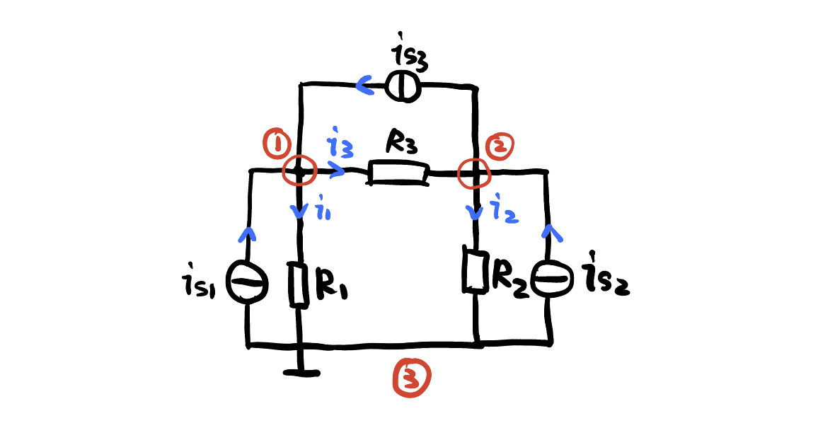
In this circuit, we have three nodes. The last node is connected to the ground, which can be seen as zero voltage. Then, let’s analyse the first and second nodes.
According to the kirchhoff’s current law, we have the equation of: − i 1 − i 3 + i s 1 + i s 3 = 0 -i_{1}-i_{3}+i_{s1}+i_{s3}=0 −i1−i3+is1+is3=0 − i 2 + i 3 + i s 2 − i s 3 = 0 -i_{2}+i_{3}+i_{s2}-i_{s3}=0 −i2+i3+is2−is3=0
We can also use Ohm’s law to replace i n i_{n} in with Δ u n r n \frac {\Delta u_{n}}{r_{n}} rnΔun, which means: i 1 = u n 1 r 1 i_{1}=\frac {u_{n1}}{r_{1}} i1=r1un1 i 2 = u n 2 r 2 i_{2}=\frac {u_{n2}}{r_{2}} i2=r2un2 i 3 = u n 1 − u n 2 r 3 i_{3}=\frac {u_{n1}-u_{n2}}{r_{3}} i3=r3un1−un2
After using electrical conductance to represent resistor and organizing the formulas, we have these equations to represent the node status: ( G 1 + G 3 ) u n 1 − G 3 u n 2 = i s 1 + i s 3 (G_{1}+G_{3})u_{n1}-G_{3}u_{n2}=i_{s1}+i_{s3} (G1+G3)un1−G3un2=is1+is3 − G 3 u n 1 + ( G 2 + G 3 ) u n 2 = i s 2 − i s 3 -G_{3}u_{n1}+(G_{2}+G_{3})u_{n2}=i_{s2}-i_{s3} −G3un1+(G2+G3)un2=is2−is3
- You can find some regularities in these equations:
- The coefficient about the node itself is the total positive conductance which it connects.
- The coefficient about other node is the negative conductance between two nodes.
- The other side of equation is the sum of positive current flowing in and negative current flowing out.
3. Matrix of Nodal Voltage Equation
Nodal equations can also be written in matrix form, take the above circuit as an example: [ G 1 + G 3 − G 3 − G 3 G 2 + G 3 ] [ u n 1 u n 2 ] = [ i s 1 + i s 3 i s 2 − i s 3 ] \begin{bmatrix} G_{1}+G_{3}&-G_{3}\\-G_{3}&G_{2}+G_{3}\end{bmatrix}\begin{bmatrix}u_{n1}\\u_{n2}\end{bmatrix}=\begin{bmatrix}i_{s1}+i_{s3}\\i_{s2}-i_{s3}\end{bmatrix} [G1+G3−G3−G3G2+G3][un1un2]=[is1+is3is2−is3]
Or we can write this matrix equation concisely: G n U n = I S n \mathbf{G_{n}}\mathbf{U_{n}}=\mathbf{I_{Sn}} GnUn=ISn
- Notation:
- G n \mathbf{G_{n}} Gn: Conductance matrix of the circuit
- U n \mathbf{U_{n}} Un: Nodal voltage matrix of the circuit
- I S n \mathbf{I_{Sn}} ISn: Nodal current sources matrix of the circuit
With this equation, we can use computer to solve any of matrix if we know other two matrix, that is the basic theory of Circuit Model and Simulation with Computer.
Please clearly mark the source of the article in the process of reproducing it! Respect for originality and intellectual property rights, thanks!


 7857
7857

 被折叠的 条评论
为什么被折叠?
被折叠的 条评论
为什么被折叠?
 到【灌水乐园】发言


