[移动通讯]【Carrier Aggregation-11】【5G NR Carrier Aggregation (CA) basics 】

本文介绍了5GNR载波聚合的基本概念,包括LTE和NR的载波聚合数量,不同类型的聚合方式(连续和非连续),以及5GPhase-1的特性。文章还讨论了5GCA的频率要求和双连接模式,以及它带来的优点,如增加带宽和网络效率提升。

摘要生成于 C知道 ,由 DeepSeek-R1 满血版支持, 前往体验 >

前言:

   参考:

               RF  Wireless world 里面的

               《5G/NR - Carrier Aggregation》

               《5G NR Carrier Aggregation (CA) basics | Carrier Aggregation frequency bands》

               
This page describes 5G NR Carrier Aggregation (CA) basics.
It mentions Carrier Aggregation/Dual Connectivity LTE 5G NR frequency bands 
and benefits or advantages of carrier aggregation in wireless systems such as 5G NR. 
It mentions minimum requirements of carrier aggregation in 5G NR.

目录:

    1: Introduction


一  Introduction:

  1.1 LTE

    CA 的概念最早在LTE Release-10 引入。

    载波聚合是指多个载波的级联。这增加了系统的带宽和连续数据速率。

    LTE R-10  支持5个CC(载波分量)的聚合

    LTE 支持带宽为 1.4,3,5,10 and 20MHz.在带宽20MHz下面,聚合5个CCs

则最大带宽为100MHz.  LTE R-13(LTE Advanced-PRO),支持32 CCs,因此

可以实现640MHz的带宽.

 1.2 NR

      NR 支持载波聚合的数量为16

      载波聚合 NR+LTE 称为 ENDC

      UE 根据其能力在一个 或者多个 CCs 下面

      连续CC和非连续CC都支持CA。

      当部署CA时,帧定时和SFN在可以聚合的小区之间对齐


  The concept of CA is introduced in LTE Release-10.
• Carrier aggregation refers to concatenation of multiple carriers. This increases bandwidth and consecutively data rate of the system. LTE R-10 provides support for 5 CCs (Component Carriers).
• LTE supports five bandwidth options 1.4, 3, 5, 10 and 20 MHz. With maximum bandwidth and 5 CCs, LTE gives maximum bandwidth of 100 MHz. LTE R-13 (i.e. LTE Advanced-PRO), supports 32 CCs, hence 640 MHz can be achieved.


  5G NR supports carrier aggregation with 16 CCs.
• Carrier aggregation of LTE and 5G NR carriers is also possible which is known as Dual Connectivity (DC).

• As mentioned in Carrier Aggregation (CA) two or more Component Carriers (CCs) are aggregated.
• A UE may simultaneously receive or transmit on one or multiple CCs depending on its capabilities.
• CA is supported for both contiguous and non-contiguous CCs.
• When CA is deployed frame timing and SFN are aligned across cells which can be aggregated.

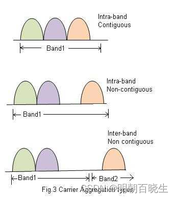
As shown in the figure-1 there are three types of carrier aggregation in general.

CA 聚合的类型
• Intra-band contiguous
• Intra-band non-contiguous
• Inter-band non-contiguous 


二 5G NR Carrier Aggregation

      5G NR Phase-1, 高达16 CCs

     • In 5G NR Phase-1, upto 16 CCs (both contiguous and non-contiguous) can be aggregated.
• Upto 1 GHz of spectrum can be aggregated.
• Carriers can use different numerologies (i.e. SCS, slots etc.)
• Transport block mapping is per carrier basis.
• Cross-carrier scheduling and joint feedback are supported.
• Carrier aggregation in 5G NR is used for both FR1 (below 6 GHz) and FR2 (above 6 GHz in mmwave range) frequency bands.

      在 5G NR Phase-1 高达 可以聚合 16个 CCs(contiguous and non-contiguous) .

       最高 1G Hz 频谱聚合

       载波可以使用不同的参数(SCS, slots)

      传输块映射 到 每个CA

      支持CRS

      5G NR FR1(<(below 6 GHz)&  and FR2 (above 6 GHz in mmwave range) 

      都支持CA.


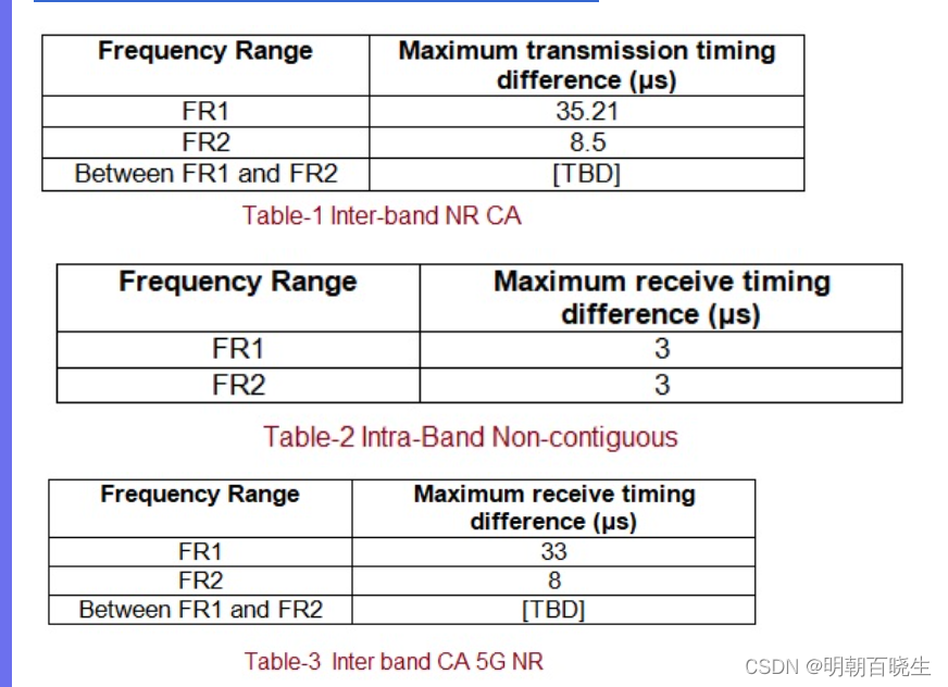
四  Minimum requirements of carrier aggregation in 5G NR

     Following tables mentions minimum requirements of carrier aggregation in intra-band and inter-band modes. These tables are derived from 3GPP TS 38.133 document.      


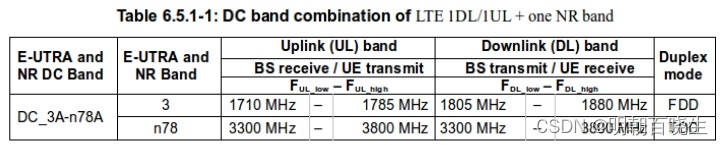
五 Dual Connectivity | LTE and 5G NR Carrier Aggregation Frequency Bands

      In Dual connectivity carrier aggregation mode both LTE carriers and 5G NR carriers are combined. The frequency bands for this are mentioned in the table below.  


 六  Advantages of Carrier Aggregation

 ➤Bandwidth increases and hence data rates or throughputs increase for both uplink and downlink.
➤Network operators have choice to deploy in any of the three CA types.
➤It helps in aggregation of licensed and un-licensed spectrums.
➤The concept can be used for both TDD and FDD topologies.
➤It helps in improvement of network efficiency.

Contents Foreword 7 1 Scope 8 2 References 8 3 Abbreviations and Definitions 9 3.1 Abbreviations 9 3.2 Definitions 9 4 Overall Architecture and Functional Split 10 4.1 Overall Architecture 10 4.2 Functional Split 11 4.3 Network Interfaces 13 4.3.1 NG Interface 13 4.3.1.1 NG User Plane 13 4.3.1.2 NG Control Plane 13 4.3.2 Xn Interface 14 4.3.2.1 Xn User Plane 14 4.3.2.2 Xn Control Plane 14 4.4 Radio Protocol Architecture 15 4.4.1 User Plane 15 4.4.2 Control Plane 15 4.5 Multi-RAT Dual Connectivity 16 5 Physical Layer 16 5.1 Waveform, numerology and frame structure 16 5.2 Downlink 17 5.2.1 Downlink transmission scheme 17 5.2.2 Physical-layer processing for physical downlink shared channel 17 5.2.3 Physical downlink control channels 18 5.2.4 Synchronization signal and PBCH 18 5.2.5 Physical layer procedures 19 5.2.5.1 Link adaptation 19 5.2.5.2 Power Control 19 5.2.5.3 Cell search 19 5.2.5.4 HARQ 19 5.3 Uplink 19 5.3.1 Uplink transmission scheme 19 5.3.2 Physical-layer processing for physical uplink shared channel 19 5.3.3 Physical uplink control channel 20 5.3.4 Random access 21 5.3.5 Physical layer procedures 21 5.3.5.1 Link adaptation 21 5.3.5.2 Uplink Power control 21 5.3.5.3 Uplink timing control 21 5.3.5.4 HARQ 21 5.4 Carrier aggregation 21 5.4.1 Carrier aggregation 21 5.4.2 Supplemental Uplink 22 5.5 Transport Channels 22 6 Layer 2 23 6.1 Overview 23 6.2 MAC Sublayer 24 6.2.1 Services and Functions 24 6.2.2 Logical Channels 25 6.2.3 Mapping to Transport Channels 25 6.2.4 HARQ 25 6.3 RLC Sublayer 25 6.3.1 Transmission Modes 25 6.3.2 Services and Functions 26 6.3.3 ARQ 26 6.4 PDCP Sublayer 26 6.4.1 Services and Functions 26 6.5 SDAP Sublayer 27 6.6 L2 Data Flow 27 6.7 Carrier Aggregation 27 6.8 Dual Connectivity 29 6.9 Supplementary Uplink 29 6.10 Bandwidth Adaptation 29 7 RRC 30 7.1 Services and Functions 30 7.2 Protocol States 31 7.3 System Information Handling 31 7.4 Access Control 32 7.5 UE Capability Retrieval framework 32 7.6 Transport of NAS Messages 33 7.7 Carrier Aggregation 33 7.8 Bandwidth Adaptation 33 8 NG Identities 33 8.1 UE Identities 33 8.2 Network Identities 33 9 Mobility and State Transitions 34 9.1 Overview 34 9.2 Intra-NR 34 9.2.1 Mobility in RRC_IDLE 34 9.2.1.1 Cell Selection 34 9.2.1.2 Cell Reselection 35 9.2.2 Mobility in RRC_INACTIVE 35 9.2.2.1 Overview 35 9.2.2.2 Cell Reselection 36 9.2.2.3 RAN-Based Notification Area 36 9.2.2.4 State Transitions 37 9.2.2.4.1 UE triggered transition from RRC_INACTIVE to RRC_CONNECTED 37 9.2.2.4.2 Network triggered transition from RRC_INACTIVE to RRC_CONNECTED 37 9.2.2.5 RNA update 38 9.2.3 Mobility in RRC_CONNECTED 38 9.2.3.1 Overview 38 9.2.3.2 Handover 39 9.2.3.2.1 C-Plane Handling 39 9.2.3.2.2 U-Plane Handling 41 9.2.4 Measurements 41 9.2.5 Paging 43 9.2.6 Random Access Procedure 43 9.2.7 Radio Link Failure 44 9.3 Inter RAT 44 9.3.1 Intra 5GC 44 9.3.1.1 Cell Reselection 44 9.3.1.2 Handover 45 9.3.1.3 Measurements 45 9.3.2 From 5GC to EPC 45 9.3.2.1 Cell Reselection 45 9.3.2.2 Handover 45 9.3.2.3 Measurements 45 9.3.2.4 Data Forwarding 45 9.4 Roaming and Access Restrictions 46 10 Scheduling 46 10.1 Basic Scheduler Operation 46 10.2 Downlink Scheduling 46 10.3 Uplink Scheduling 47 10.4 Measurements to Support Scheduler Operation 47 10.5 Rate Control 47 10.5.1 Downlink 47 10.5.2 Uplink 48 10.6 Activation/Deactivation Mechanism 48 11 UE Power Saving 48 12 QoS 49 13 Security 50 13.1 Overview and Principles 50 13.2 Security Termination Points 51 13.3 State Transitions and Mobility 51 14 UE Capabilities 51 15 Self-Configuration and Self-Optimisation 51 15.1 Definitions 51 15.2 UE Support for self-configuration and self-optimisation 51 15.3 Self-configuration 52 15.3.1 Dynamic configuration of the NG-C interface 52 15.3.1.1 Prerequisites 52 15.3.1.2 SCTP initialization 52 15.3.1.3 Application layer initialization 52 15.3.2 Dynamic Configuration of the Xn interface 52 15.3.2.1 Prerequisites 52 15.3.2.2 SCTP initialization 52 15.3.2.3 Application layer initialization 52 15.3.3 Automatic Neighbour Cell Relation Function 52 15.3.3.1 General 52 15.3.3.2 Intra-system – intra NR Automatic Neighbour Cell Relation Function 52 15.3.3.3 Intra-system – intra E-UTRA Automatic Neighbour Cell Relation Function 53 15.3.3.4 Intra-system – inter RAT Automatic Neighbour Cell Relation Function 53 15.3.3.5 Inter-system Automatic Neighbour Cell Relation Function 53 15.3.4 Xn-C TNL address discovery 53 16 Verticals Support 53 16.1 URLLC 53 16.1.1 Overview 53 16.1.2 LCP Restrictions 53 16.1.3 Packet Duplication 53 16.2 IMS Voice 54 16.3 Network Slicing 54 16.3.1 General Principles and Requirements 54 16.3.2 CN Instance and NW Slice Selection 55 16.3.2.1 CN-RAN interaction and internal RAN aspects 55 16.3.2.2 Radio Interface Aspects 55 16.3.3 Resource Isolation and Management 55 16.3.4 Signalling Aspects 56 16.3.4.1 General 56 16.3.4.2 CN Instance and NW Slice Selection 56 16.3.4.3 UE Context Handling 56 16.3.4.4 PDU Session Handling 57 16.3.4.5 Mobility 58 16.4 Public Warning System 59 Annex A (informative): QoS Handling in RAN 60 A.1 PDU Session Establishment 60 A.2 New QoS Flow without Explicit Signalling 60 A.3 New QoS Flow with NAS Reflective QoS and Explicit RRC Signalling 61 A.4 New QoS Flow with Explicit Signalling 62 A.5 Release of QoS Flow with Explicit Signalling 63 A.6 UE Initiated UL QoS Flow 64 Annex B (informative): Deployment Scenarios 66 B.1 Supplementary Uplink 66 Annex C (informative): Change history 67
评论
添加红包

请填写红包祝福语或标题

红包个数最小为10个

红包金额最低5元

当前余额3.43前往充值 >
需支付:10.00
成就一亿技术人!
领取后你会自动成为博主和红包主的粉丝 规则
hope_wisdom
发出的红包
实付
使用余额支付
点击重新获取
扫码支付
钱包余额 0

抵扣说明:

1.余额是钱包充值的虚拟货币,按照1:1的比例进行支付金额的抵扣。
2.余额无法直接购买下载,可以购买VIP、付费专栏及课程。

余额充值