


文章目录
- Introduction to mmwave Sensing: FMCW Radars
- INTRODUCTION TO MMWAVE SENSING: FMCW RADARS Module 1 : Range Estimation
- In this module we’ll try to answer the following questions……
- What is a chirp?
- A 1TX-1RX FMCW radar
- The IF signal
- Fourier Transforms : A quick review
- Fourier Transforms: A quick review
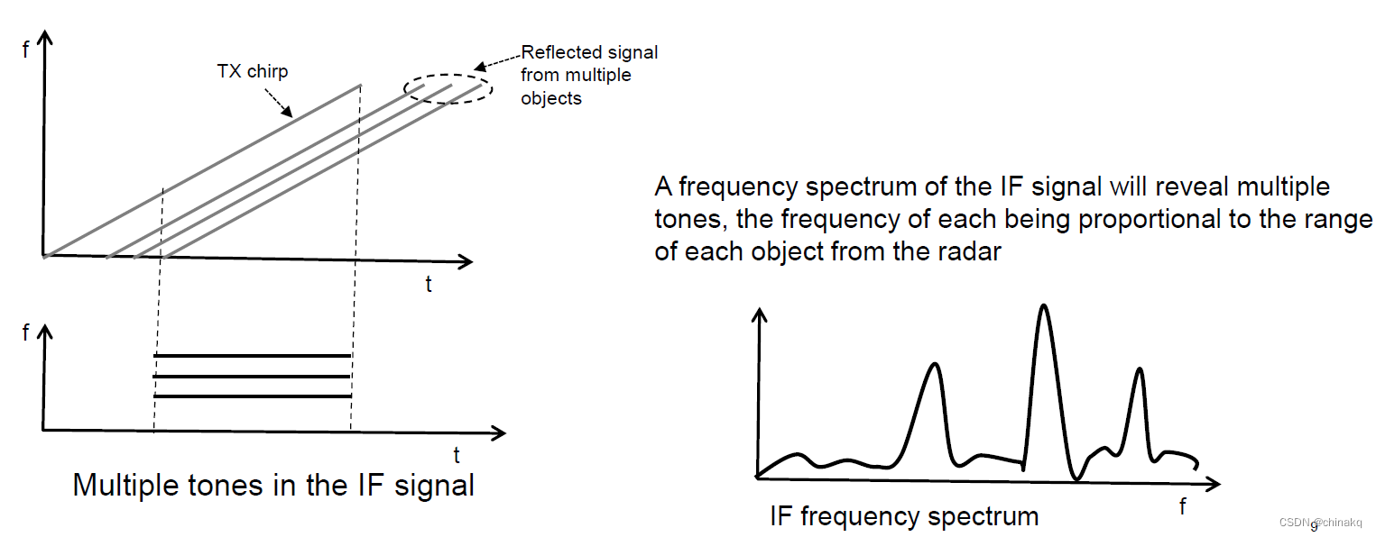
- Multiple objects in front of the radar
- Range Resolution in a radar
- Question
- Digitizing the IF signal
- Question
- Summary
- Key concepts /formulas
- Epilogue
原视频链接
Introduction to mmwave Sensing: FMCW Radars
Sandeep Rao, Texas Instruments
INTRODUCTION TO MMWAVE SENSING: FMCW RADARS Module 1 : Range Estimation
- Basics of FMCW radar operation
- Using the radar to measure range of multiple objects in front of the radar
- Concept of IF signal and IF bandwidth
- Range Resolution
In this module we’ll try to answer the following questions……
How does the radar estimate the range of an object?
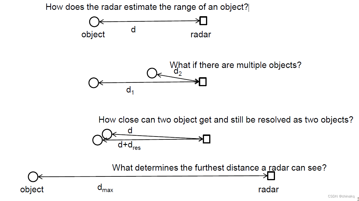
- How does the radar estimate the range of an object?
- What if there are multiple objects?
- How close can two object get and still be resolved as two objects?
- What determines the furthest distance a radar can see?
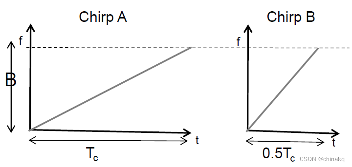
What is a chirp?
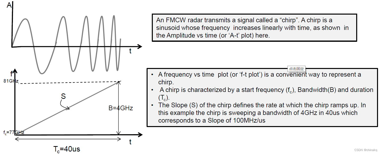
- An FMCW radar transmits a signal called a signal called a “chirp”. A chirp is a sinusoid whose frequency increases linearly with time, as shown in the Amplitude VS time (or ‘A-t’ plot) here.
- A frequency vs time plot(or ‘f-t plot’) is a convenient way to represent a chirp.
- A chirp is characterized by a start frequency(fc),Bandwidth(B) and duration(Tc).
- The Slope(S) of the chirp defines the rate at which the chirp ramps up. In this example the chirp is sweeping a bandwidth of 4GHz in 40us which corresponds to a Slope of 100MHz/us
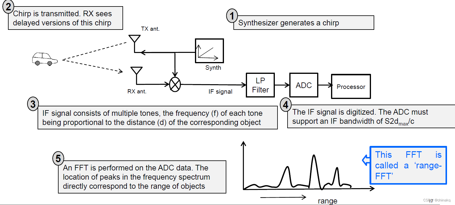
A 1TX-1RX FMCW radar
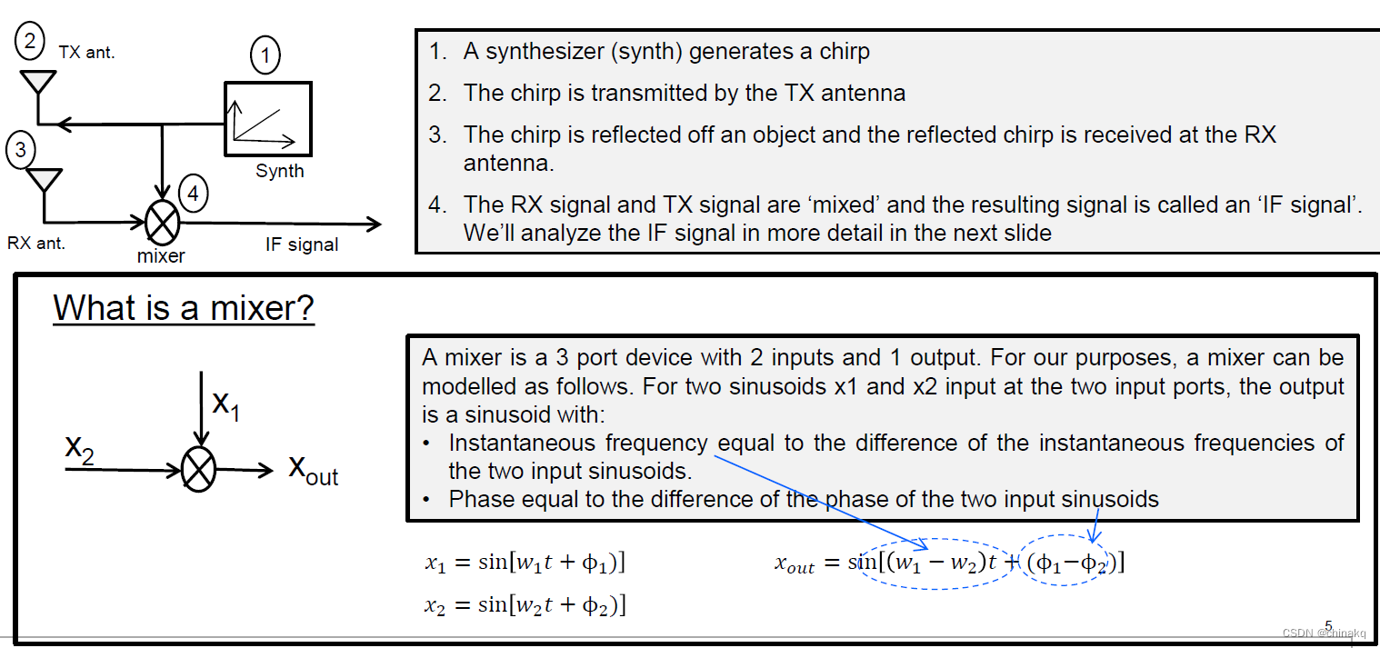
- pic.1
- A synthesizer (synth) generates a chirp.
- The chirp is transmitted by the TX antenna.
- The chirp is reflected off an object and the reflected chirp is received at the RX antenna.
- The RX signal and TX signal are ‘mixed’ and the resulting signal is called an ‘IF signal’. We’ll analyze the IF signal in more detail in the next slide.
- pic.2
A mixer is a 3 port device with 2 inputs and 1 output. For our purposes, a mixer can be modelled as follows. For two sinusoids x1 and x2 input at the two input ports, the output is a sinusoid with:- Instantaneous frequency equal to the difference of the instantaneous frequencies of the two input sinusoids.
- Phase equal to the difference of the phase of the two input sinusoids
x 1 = sin [ w 1 t + ϕ 1 ] x_1 = \sin[w_1t+\phi_1] x1=sin[w1t+ϕ1]
x 2 = sin [ w 2 t + ϕ 2 ] x_2 = \sin[w_2t+\phi_2] x2=sin[w2t+ϕ2]
x o u t = sin [ ( w 1 − w 2 ) t + ( ϕ 1 − ϕ 2 ) ] x_out = \sin[(w_1-w_2)t+(\phi_1-\phi_2)] xout=sin[(w1−w2)t+(ϕ1−ϕ2)]
The IF signal
The mixers operation can be understood easily using the f-t plot.
- The top figure shows the TX-signal and the RX-signal that is reflected from an object. Note that the RX-signal is just a delayed version of the TX signal. ( τ \tau τ denotes the round-trip time between the radar and the object. Also S denotes the slope of the chirp )
- Recall that the frequency of the signal at the mixers output is the difference of the instantaneous frequency of the TX-chirp and RX-chirp. As shown in the figure below, this is a straight line.
- Hence: A single object in front of the radar produces an IF signal that is a constant frequency tone.
- The frequency of this tone is S τ = S ∗ 2 d / c S\tau = S*2d/c Sτ=S∗2d/c; [Since τ = 2 d / c \tau = 2d/c τ=2d/c , where d is distance of the object and c is the speed of light]
- A single object in front of the radar produces an IF signal with a constant frequency of S2d/c
Note that τ \tau τ is typically a small fraction of the total chirp time =>non-overlapping segment of the TX chirp is usually negligible. E.g. For a radar with a max distance of 300m and Tc=40us. τ/Tc =5%
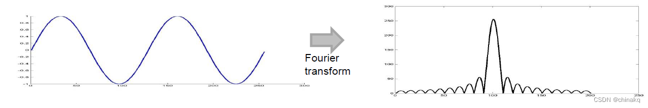
Fourier Transforms : A quick review
- Fourier Transform converts a time domain signal into the frequency domain.
- A sinusoid in the time domain produces a single peak in the frequency domain.
Fourier Transforms: A quick review
- Within the observation window T below, the red tone completes 2 cycles, while the blue tone completes 2.5 cycles. The difference of 0.5 cycles is not sufficient to resolve the tones in the frequency spectrum.
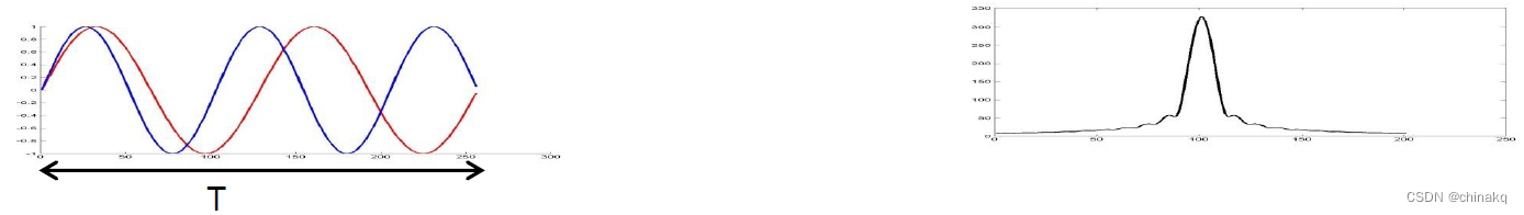
- Doubling the observation window results in a difference of 1 cycle => the tones are resolved in the frequency spectrum
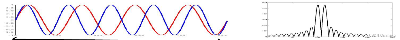
- Longer the observation period => better the resolution. In general, an observation window of T can separate frequency components that are separated by more than 1/T Hz
Multiple objects in front of the radar
- Multiple objects in front of the radar=> multiple reflected chirps at the RX antenna
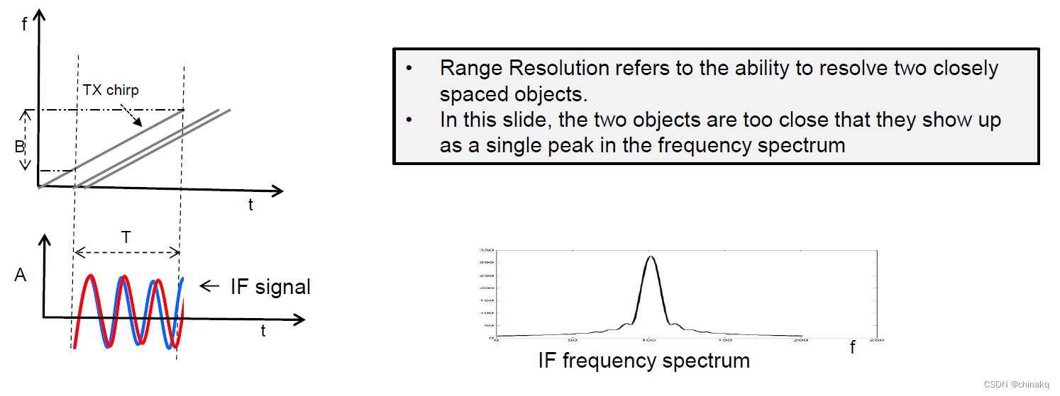
Range Resolution in a radar
-
Range Resolution refers to the ability to resolve two closely spaced objects.
-
In this slide, the two objects are too close that they show up as a single peak in the frequency spectrum.
-
recall that
- An object at a distance d results in an IF tone of frequency S2d/c
- Two tones can be resolved in frequency as long as the frequency difference Δf > 1/T
-
Can you use the above to derive an equation for the range resolution of the radar?
- On what parameters does the range resolution depend ? Chirp Duration, Bandwidth, Slope?
For two objects separated by a distance Δd, the difference in their IF frequencies is given by
Δ
f
=
S
2
Δ
d
c
\Delta f=\frac{S2\Delta d}{c}
Δf=cS2Δd
Since the observation interval is
T
c
T_c
Tc, this means that
Δ
f
>
1
T
c
⇒
S
2
Δ
d
c
>
1
T
c
⇒
Δ
d
>
c
2
S
T
c
⇒
c
2
B
(
s
i
n
c
e
B
=
S
T
c
)
\Delta f>\frac{1}{T_c}\Rightarrow\frac{S2\Delta d}{c}>\frac{1}{T_c}\Rightarrow\Delta d> \frac{c}{2ST_c}\Rightarrow \frac{c}{2B} (since B=ST_c)
Δf>Tc1⇒cS2Δd>Tc1⇒Δd>2STcc⇒2Bc(sinceB=STc)
The Range Resolution (dres) depends only on the Bandwidth swept by the chirp:
d
r
e
s
=
c
2
B
d_{res}= \frac{c}{2B}
dres=2Bc
Question
- Which of these two chirps gives a better range-resolution?
- What is the intuition behind this result?
最小解析范围
- What is the intuition behind this result?
| Bandwidth | Range resolution |
|---|---|
| 4GHz | 3.75cm |
| 2GHz | 7.5cm |
| 1GHz | 15cm |
| 600mHz | 25cm |
Digitizing the IF signal
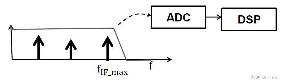
- The bandwidth of interest of the IF signal depends on the desired maximum distance: f I F _ m a x = S 2 d m a x c f_{IF\_max}=\frac{S2d_{max}}{c} fIF_max=cS2dmax
- IF signal is typically digitized (LPF+ADC) for further processing on a DSP.
- IF Bandwidth is thus limited by the ADC sampling rate (Fs).
F
s
≥
S
2
d
m
a
x
c
F_s\geq \frac{S2d_{max}}{c}
Fs≥cS2dmax
An ADC sampling rate of F s F_s Fs limits the maximum range of the radar to
d m a x = F s c 2 S d_{max}=\frac{F_sc}{2S} dmax=2SFsc
Question
- Revisiting our earlier example, what more can we now say about these two chirps?

While both Chirp A and B have the same range resolution: - For the same d m a x d_{max} dmax,Chirp A requires only half the IF bandwidth (=>smaller Fs on the ADC).
- But Chirp B has the advantage of requiring half the measurement time.
Summary
Key concepts /formulas
- An object at a distance d produces an IF frequency of:
- f I F = S 2 d c f_{IF}=\frac{S2d}{c} fIF=cS2d
- Range resolution ( d r e s d_{res} dres) depends on the bandwidth (B):
- d r e s = c 2 B d_{res}=\frac{c}{2B} dres=2Bc
- The ADC sampling rate
F
s
F_s
Fs, limits the max range (
d
m
a
x
d_{max}
dmax) to
- d m a x = F s c 2 S d_{max} = \frac{F_sc}{2S} dmax=2SFsc
Chirp Bandwidth vs IF bandwidth?
Larger Chirp Bandwidth => better range resolution
Larger IF Bandwidth => faster chirps , better maximum distance
Epilogue
Two objects equidistant from the radar. How will the range–FFT look like?
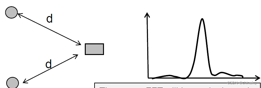
- The range-FFT will have single peak corresponding to the range d
- How do we separate these two objects?
- It turns out that if the 2 objects have different velocities relative to the radar, then these objects can be separated out by further signal processing. To understand that we need to look at the phase of the IF-signal and which is something we will do in the next module.


 1336
1336


 被折叠的 条评论
为什么被折叠?
被折叠的 条评论
为什么被折叠?
 到【灌水乐园】发言


