


 本文介绍了在Unity 2018.1 beta中如何使用Shader Graph的自定义节点API,特别是代码功能节点。通过C#脚本创建自定义节点,可以扩展Shader Graph的功能,满足特定的着色器需求。示例展示了如何定义节点的输入和输出端口,以及编写HLSL代码来实现所需功能。

小波包节点系数 时频图着色
With the recent addition of Shader Graph, it’s now easier than ever to create custom shaders in Unity. However, regardless of how many different Nodes we offer by default, we can’t possibly cater for everything you might want to make. For this reason, we have developed a Custom Node API for you to use to make new Nodes in C#. This allows you to extend Shader Graph to suit your needs.
通过最近添加的Shader Graph,现在比以往更容易在Unity中创建自定义着色器。 但是,无论默认情况下我们提供多少个不同的节点,我们都无法满足您可能要制作的所有内容。 因此,我们开发了一个自定义节点API,供您使用C#创建新节点。 这使您可以扩展Shader Graph以适合您的需求。
In this blog post, we will take a look at one of the ways you can do this in Unity 2018.1 beta. The simplest way to create custom Nodes that create shader functions is the Code Function Node. Let’s take a look at how to create a new Node using this method.
在此博客文章中,我们将介绍在 Unity 2018.1 beta中 实现此目的的方法之一 。 创建创建着色器功能的自定义节点的最简单方法是代码功能节点。 让我们看一下如何使用此方法创建新的Node。
Let’s start by creating a new C# script. For this example, I have named the script MyCustomNode. To use the Code Function Node API you need to include (or add the class to) the namespace UnityEditor.ShaderGraph and inherit from the base class CodeFunctionNode.
让我们从创建一个新的C#脚本开始。 在此示例中,我将脚本命名为 MyCustomNode 。 要使用代码功能节点API,您需要包括名称空间 UnityEditor.ShaderGraph (或将其添加到名称空间) 并从基类 CodeFunctionNode 继承 。
|
1
2
3
4
5
6
7
|
using UnityEngine;
using UnityEditor.ShaderGraph;
public class MyCustomNode : CodeFunctionNode
{
}
|
|
1
2
3
4
5
6
7
|
using UnityEngine ;
using UnityEditor . ShaderGraph ;
public class MyCustomNode : CodeFunctionNode
{
}
|
The first thing you will notice is that MyCustomNode is highlighted with an error. If we hover over the message we see that we need to implement an inherited member called GetFunctionToConvert. The base class CodeFunctionNode handles most of the work that needs to be done to tell the Shader Graph how to process this Node, but we still need to tell it what the resulting function should be.
您会注意到的第一件事是 MyCustomNode 突出显示并带有错误。 如果将鼠标悬停在消息上,则会看到我们需要实现一个名为 GetFunctionToConvert 的继承成员 。 基类 CodeFunctionNode 处理了需要完成的大多数工作,以告诉Shader Graph如何处理此Node,但是我们仍然需要告诉它结果函数应该是什么。
The method GetFunctionToConvert uses Reflection to convert another method into an instance of MethodInfo that CodeFunctionNode can convert for use in Shader Graph. This simply allows us to write the shader function we want in a more intuitive way.
该方法 GetFunctionToConvert 使用反射来的另一种方法转换成 一个MethodInfo 的实例 CodeFunctionNode 可以为着色器使用的图形转换。 这仅允许我们以更直观的方式编写所需的着色器功能。
For more information on Reflection see Microsoft’s Programming Guide on Reflection (C#).
有关反射的更多信息,请参见Microsoft的反射编程指南 (C#) 。
Add the namespace System.Reflection and the override function GetFunctionToConvert as shown in the example below. Note the string that reads MyCustomFunction. This will be the name of the function that is written into the final shader. This can be named whatever you wish to suit the function you are writing and can be anything that doesn’t begin with a numeric character, but for the rest of this article we will assume its name is MyCustomFunction.
添加名称空间 System.Reflection 和覆盖函数 GetFunctionToConvert ,如下例所示。 请注意读取 MyCustomFunction 的字符串 。 这将是写入最终着色器的函数的名称。 可以根据您要编写的函数来命名它,也可以不以数字字符开头,但是对于本文的其余部分,我们将假定其名称为 MyCustomFunction 。
|
1
2
3
4
5
6
7
8
9
10
11
12
|
using UnityEngine;
using UnityEditor.ShaderGraph;
using System.Reflection;
public class MyCustomNode : CodeFunctionNode
{
protected override MethodInfo GetFunctionToConvert()
{
return GetType().GetMethod("MyCustomFunction",
BindingFlags.Static | BindingFlags.NonPublic);
}
}
|
|
1
2
3
4
5
6
7
8
9
10
11
12
|
using UnityEngine ;
using UnityEditor . ShaderGraph ;
using System . Reflection ;
public class MyCustomNode : CodeFunctionNode
{
protected override MethodInfo GetFunctionToConvert ( )
{
return GetType ( ) . GetMethod ( "MyCustomFunction" ,
BindingFlags . Static | BindingFlags . NonPublic ) ;
}
}
|
Now that our script errors are resolved, we can start working on the functionality of our new Node! Before we continue we should name it. To do this add a public constructor for the class with no arguments. In it, set the variable name to a string that contains the title of your Node. This will be displayed in the title bar of the Node when it appears in a graph. For this example, we will call the Node My Custom Node.
现在,我们的脚本错误已解决,我们可以开始使用新Node的功能! 在继续之前,我们应该先命名。 为此,为该类添加一个不带参数的公共构造函数。 在其中,将变量 名 设置为 包含节点标题的字符串。 当它出现在图形中时,它将显示在节点的标题栏中。 对于此示例,我们将其称为Node My Custom Node 。
|
1
2
3
4
5
6
7
8
9
10
11
12
13
14
15
16
17
|
using UnityEngine;
using UnityEditor.ShaderGraph;
using System.Reflection;
public class MyCustomNode : CodeFunctionNode
{
public MyCustomNode()
{
name = "My Custom Node";
}
protected override MethodInfo GetFunctionToConvert()
{
return GetType().GetMethod("MyCustomFunction",
BindingFlags.Static | BindingFlags.NonPublic);
}
}
|
|
1
2
3
4
5
6
7
8
9
10
11
12
13
14
15
16
17
|
using UnityEngine ;
using UnityEditor . ShaderGraph ;
using System . Reflection ;
public class MyCustomNode : CodeFunctionNode
{
public MyCustomNode ( )
{
name = "My Custom Node" ;
}
protected override MethodInfo GetFunctionToConvert ( )
{
return GetType ( ) . GetMethod ( "MyCustomFunction" ,
BindingFlags . Static | BindingFlags . NonPublic ) ;
}
}
|
Next, we will define the Node’s function itself. If you are familiar with Reflection you will notice that the method GetFunctionToConvert is attempting to access a method in this class called MyCustomFunction. This is the method that will define the shader function itself.
接下来,我们将定义节点的功能本身。 如果您熟悉Reflection,您会注意到 GetFunctionToConvert 方法 正在尝试访问此类中的方法 MyCustomFunction 。 这是定义着色器功能本身的方法。
Let’s create a new static method of return type string with the same name as the string in the method GetFunctionToConvert. In this case it’s MyCustomFunction. In the arguments of this method we can define what Ports we want the Node to have. These will map directly to the arguments in the final shader function. We do this by adding an argument of a type supported in Shader Graph with a Slot Attribute. For now, let’s add two arguments of type DynamicDimensionVector called A and B and another out argument of type DynamicDimensionVector called Out. Then we will add a default Slot Attribute to each of these arguments. Each Slot Attribute needs a unique index and a binding, which we will set to None.
让我们创建一个新的静态返回类型为 string的 静态方法, 该方法与 GetFunctionToConvert 方法中的字符串同名 。 在这种情况下,它是 MyCustomFunction 。 在此方法的参数中,我们可以定义希望节点具有的端口。 这些将直接映射到最终着色器函数中的参数。 为此,我们添加了带有 Slot属性的 Shader Graph支持的类型的参数 。 现在,让我们添加型 DynamicDimensionVector 的两个参数, 称为 A 和 B, 大声 型 DynamicDimensionVector 的 另一 出 论点 。 然后,我们将向 每个这些参数 添加默认的 Slot属性 。 每个 Slot属性都 需要一个唯一的索引和一个绑定,我们将其设置为 None 。
|
1
2
3
4
5
6
7
|
static string MyCustomFunction(
[Slot(0, Binding.None)] DynamicDimensionVector A,
[Slot(1, Binding.None)] DynamicDimensionVector B,
[Slot(2, Binding.None)] out DynamicDimensionVector Out)
{
}
|
|
1
2
3
4
5
6
7
|
static string MyCustomFunction (
[ Slot ( 0 , Binding . None ) ] DynamicDimensionVector A ,
[ Slot ( 1 , Binding . None ) ] DynamicDimensionVector B ,
[ Slot ( 2 , Binding . None ) ] out DynamicDimensionVector Out )
{
}
|
For a full list of types and bindings that are supported see the CodeFunctionNode API documentation on GitHub.
有关支持的类型和绑定的完整列表,请参见 GitHub上 的 CodeFunctionNode API文档 。
In the following method we will define the contents of the shader function in the return string. This needs to contain the braces of the shader function and the HLSL code we wish to include. For this example let’s define Out = A + B;. The method we just created should look like this:
在以下方法中,我们将在返回字符串中定义着色器函数的内容。 这需要包含着色函数的花括号和我们希望包括的HLSL代码。 在这个例子中,我们定义 Out = A + B; 。 我们刚刚创建的方法应如下所示:
|
1
2
3
4
5
6
7
8
9
10
11
12
13
|
static string MyCustomFunction(
[Slot(0, Binding.None)] DynamicDimensionVector A,
[Slot(1, Binding.None)] DynamicDimensionVector B,
[Slot(2, Binding.None)] out DynamicDimensionVector Out)
{
return
@"
{
Out = A + B;
}
";
}
}
|
|
1
2
3
4
5
6
7
8
9
10
11
12
13
|
static string MyCustomFunction (
[ Slot ( 0 , Binding . None ) ] DynamicDimensionVector A ,
[ Slot ( 1 , Binding . None ) ] DynamicDimensionVector B ,
[ Slot ( 2 , Binding . None ) ] out DynamicDimensionVector Out )
{
return
@ "
{
Out = A + B;
}
" ;
}
}
|
This is exactly the same C# code that is used in the Add Node that comes with Shader Graph.
这 与Shader Graph随附 的“ 添加节点” 中 使用的C#代码完全相同 。
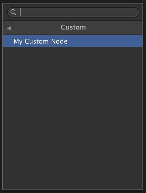
There is one last thing we need to do before we have a working Node: tell it where to appear in the Create Node Menu. We do this by adding the Title Attribute above the class.This defines a string array that describes where it should appear in the hierarchy in the menu. The last string in this array defines what the Node should be called in the Create Node Menu. For this example, we will call the Node My Custom Node and place it in the folder Custom.
在拥有可用的Node之前,我们需要做的最后一件事:告诉它出现在 Create Node Menu中的位置 。 为此,我们在类 上方 添加 Title属性 ,它定义了一个 字符串 数组, 该 字符串 数组描述了它应该在菜单的层次结构中出现的位置。 该数组中的最后一个字符串定义在“ 创建节点菜单”中 应调用的 节点 。 对于此示例,我们将调用“节点 我的自定义节点” 并将其放置在文件夹 Custom中 。
|
1
2
3
|
[Title("Custom", "My Custom Node")]
public class MyCustomNode : CodeFunctionNode
{
|
|
1
2
3
|
[ Title ( "Custom" , "My Custom Node" ) ]
public class MyCustomNode : CodeFunctionNode
{
|
Now we have a working Node! If we return to Unity, let the script compile then open Shader Graph we will see the new Node in the Create Node Menu.
现在我们有了一个工作节点! 如果返回Unity, 请先 编译脚本,然后打开Shader Graph,然后在 Create Node Menu 中将看到新的Node 。
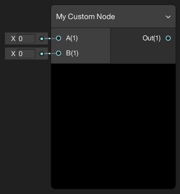
Create an instance of the Node in the Shader Graph. You will see it has the Ports we defined with the same names and types as the arguments to the MyCustomFunction class.
在明暗器图中创建节点的实例。 您将看到它具有我们定义的端口,其名称和类型与 MyCustomFunction 类 的参数相同 。
Now we can create all kinds of different Nodes by using different Port types and bindings. The return string of the method can contain any valid HLSL in a regular Unity shader. Here is a Node that returns the smallest of the three input values:
现在,我们可以使用不同的端口类型和绑定来创建各种不同的节点。 该方法的返回字符串可以在常规Unity着色器中包含任何有效的HLSL。 这是一个返回三个输入值中最小的一个的节点:
|
1
2
3
4
5
6
7
8
9
10
11
12
13
14
|
static string Min3(
[Slot(0, Binding.None)] DynamicDimensionVector A,
[Slot(1, Binding.None)] DynamicDimensionVector B,
[Slot(2, Binding.None)] DynamicDimensionVector C,
[Slot(3, Binding.None)] out DynamicDimensionVector Out)
{
return
@"
{
Out = min(min(A, B), C);
}
";
}
}
|
|
1
2
3
4
5
6
7
8
9
10
11
12
13
14
|
static string Min3 (
[ Slot ( 0 , Binding . None ) ] DynamicDimensionVector A ,
[ Slot ( 1 , Binding . None ) ] DynamicDimensionVector B ,
[ Slot ( 2 , Binding . None ) ] DynamicDimensionVector C ,
[ Slot ( 3 , Binding . None ) ] out DynamicDimensionVector Out )
{
return
@ "
{
Out = min(min(A, B), C);
}
" ;
}
}
|
And here is a Node that inverts normals based on a Boolean input. Note in this example how the Port Normal has a binding for WorldSpaceNormal. When there is no Edge connected to this Port it will use the mesh’s world space normal vector by default. For more information see the Port Binding documentation on GitHub. Also note how when using a concrete output type like Vector 3 we have to define it before we return the shader function. Note that this value is not used.
这是一个根据布尔输入反转法线的节点。 请注意,在此示例中,“端口 普通” 如何与 WorldSpaceNormal 绑定 。 当没有边缘连接到此端口时,默认情况下它将使用网格物体的世界空间法向矢量。 有关更多信息,请参见 GitHub上 的 Port Binding文档 。 还要注意,当使用诸如Vector 3的具体输出类型时,如何在返回着色器函数之前必须对其进行定义。 请注意,不使用此值。
|
1
2
3
4
5
6
7
8
9
10
11
12
13
14
|
static string FlipNormal(
[Slot(0, Binding.WorldSpaceNormal)] Vector3 Normal,
[Slot(1, Binding.None)] Boolean Predicate,
[Slot(2, Binding.None)] out Vector 3 Out)
{
Out = Vector3.zero;
return
@"
{
Out = Predicate == 1 ? -1 * Normal : Normal;;
}
";
}
}
|
|
1
2
3
4
5
6
7
8
9
10
11
12
13
14
|
static string FlipNormal (
[ Slot ( 0 , Binding . WorldSpaceNormal ) ] Vector3 Normal ,
[ Slot ( 1 , Binding . None ) ] Boolean Predicate ,
[ Slot ( 2 , Binding . None ) ] out Vector 3 Out )
{
Out = Vector3 . zero ;
return
@ "
{
Out = Predicate == 1 ? -1 * Normal : Normal;;
}
" ;
}
}
|
Now you are ready to try making Nodes in Shader Graph using Code Function Node! But this is, of course, just the beginning. There is much more you can do in Shader Graph to customize the system.
现在,您准备尝试使用代码功能节点在明暗器图中制作节点! 但这当然仅仅是开始。 您可以在Shader Graph中做更多的事情来自定义系统。
Stay tuned to this blog and talk to us on the Forums!
请继续关注此博客,并 在论坛上与我们交谈 !
翻译自: https://blogs.unity3d.com/2018/03/27/shader-graph-custom-node-api-using-the-code-function-node/
小波包节点系数 时频图着色


 497
497

 被折叠的 条评论
为什么被折叠?
被折叠的 条评论
为什么被折叠?
 到【灌水乐园】发言


