


unity 粒子 运动模糊

Blurry is a set of scripts that allow you to easily visualize simple geometrical shapes with a bokeh/depth of field effect of an out-of-focus camera. It uses Three.js internally to make it easy to develop the shaders and the WebGL programs required to run it.
模糊是一组脚本,可让您使用散焦相机的散景/景深效果轻松可视化简单的几何形状。 它在内部使用Three.js使开发着色器和运行它所需的WebGL程序变得容易。
The bokeh effect is generated by using millions of particles to draw the primitives supported by the library. These particles are then accumulated in a texture and randomly displaced in a circle depending on how far away they are from the focal plane.
通过使用数百万个粒子绘制库支持的图元来生成散景效果。 然后,这些粒子将以纹理的形式积累,并根据它们离焦平面的距离随机地排列成一个圆形。
These are some of the scenes I’ve recently created using Blurry:
这些是我最近使用模糊创建的一些场景:
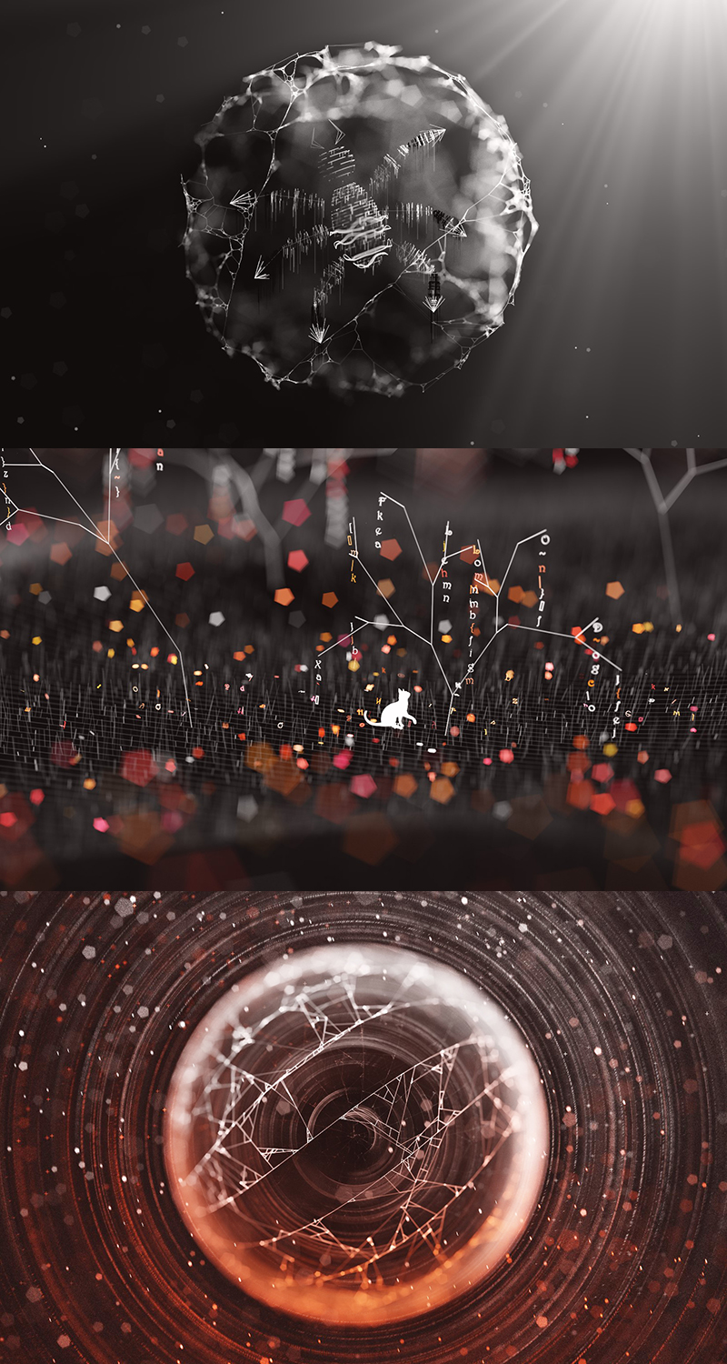
Since the library itself is very simple and you don’t need to know more than three functions to get started, I’ve decided to write this walk-through of a scene made with Blurry. It will teach you how to use various tricks to create geometrical shapes often found in the works of generative artists. This will also hopefully show you how simple tools can produce interesting and complex looking results.
由于库本身非常简单,并且您不需要了解三个以上的函数就可以开始使用,因此我决定编写使用Blurry制作的场景的本演练。 它将教您如何使用各种技巧来创建生成艺术家作品中经常出现的几何形状。 这也有望向您显示简单的工具如何产生有趣而复杂的结果。
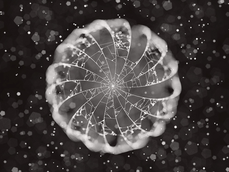
In this little introduction to Blurry we’ll try to recreate the following scene, by using various techniques borrowed from the world of generative art:
在这个关于模糊的简短介绍中,我们将尝试使用从生成艺术的世界中借鉴的各种技术来重新创建以下场景:

起步 (Starting out)
You can download the repo here and serve index.html from a local server to render the scene that is currently coded inside libs/createScene.js. You can rotate, zoom and pan around the scene as with any Three.js project using OrbitControls.js.
您可以在此处下载存储库,并从本地服务器提供index.html,以渲染当前在libs / createScene.js中编码的场景。 您可以使用OrbitControls.js像任何Three.js项目一样旋转,缩放和平移场景。
There are also some additional key-bindings to change various parameters of the renderer, such as the focal length, exposure, bokeh strength and more. These are visible at the bottom left of the screen.
还有一些其他的按键绑定可以更改渲染器的各种参数,例如焦距,曝光,散景强度等。 这些在屏幕的左下方可见。
All the magic happens inside libs/createScene.js, where you can implement the two functions required to render something with Blurry. All the snippets defined in this article will end up inside createScene.js.
所有的魔术都发生在libs / createScene.js中,您可以在其中实现使用Blurry渲染某些东西所需的两个功能。 本文定义的所有代码段都将最终保存在createScene.js中。
The most important function we’ll need to implement to recreate the scene shown at the beginning of the article is createScene(), which will be called by the other scripts just before the renderer pushes the primitives to the GPU for the actual rendering of the scene.
要重新创建本文开头显示的场景,我们需要实现的最重要的功能是createScene() ,在渲染器将基元推入GPU进行实际渲染之前,其他脚本将调用该函数。现场。
The other function we’ll define is setGlobals(), which is used to define the parameters of the shaders that will render our scene, such as the strength of the bokeh effect, the exposure, background color, etc.
我们将定义的另一个函数是setGlobals() ,该函数用于定义将渲染场景的着色器的参数,例如散景效果的强度,曝光度,背景色等。
Let’s head over to createScene.js, remove everything that’s already coded in there, and define setGlobals() as:
让我们前往createScene.js,删除其中已经编码的所有内容,并将setGlobals()定义为:
function setGlobals() {
    pointsPerFrame = 50000;

    cameraPosition = new THREE.Vector3(0, 0, 115);
    cameraFocalDistance = 100;

    minimumLineSize = 0.005;

    bokehStrength = 0.02;
    focalPowerFunction = 1;
    exposure = 0.009;
    distanceAttenuation = 0.002;

    useBokehTexture = true;
    bokehTexturePath = "assets/bokeh/pentagon2.png";

    backgroundColor[0] *= 0.8;
    backgroundColor[1] *= 0.8;
    backgroundColor[2] *= 0.8;
}
There’s an explanation for each of these parameters in the Readme of the GitHub repo. The important info at the moment is that the camera will start positioned at (x: 0, y: 0, z: 115) and the cameraFocalDistance (the distance from the camera where our primitives will be in focus) will be set at 100, meaning that every point 100 units away from the camera will be in focus.
GitHub repo的自述文件中对每个参数都有解释。 此刻的重要信息是,摄像头将开始位于(x:0,y:0,z:115)处,并且cameraFocalDistance (与将聚焦图元的摄像头之间的距离)将设置为100,意味着距离相机100个单位的每个点都会清晰对焦。
Another variable to consider is pointsPerFrame, which is used internally to assign a set number of points to all the primitives to render in a single frame. If you find that your GPU is struggling with 50000, lower that value.
要考虑的另一个变量是pointsPerFrame ,它在内部用于为所有要在单个帧中渲染的图元分配一定数量的点。 如果发现您的GPU挣扎于50000,请降低该值。
Before we start implementing createScene(), let’s first define some initial global variables that will be useful later:
在开始实现createScene()之前,让我们先定义一些初始全局变量,这些变量稍后将有用:
let rand, nrand;
let vec3 = function(x,y,z) { return new THREE.Vector3(x,y,z) };
I’ll explain the usage of each of these variables as we move along; vec3() is just a simple shortcut to create Three.js vectors without having to type THREE.Vector3(…) each time.
我将在继续介绍这些变量的用法。 vec3()只是创建Three.js向量的简单快捷方式,而不必每次都键入THREE.Vector3(…)。
Let’s now define createScene():
现在让我们定义createScene() :
function createScene() {
    Utils.setRandomSeed("3926153465010");

    rand = function() { return Utils.rand(); };
    nrand = function() { return rand() * 2 - 1; };
}
Very often I find the need to “repeat” the sequence of randomly generated numbers I had in a bugged scene. If I had to rely on the standard Math.random() function, each page-refresh would give me different random numbers, which is why I’ve included a seeded random number generator in the project. Utils.setRandomSeed(…) will take a string as a parameter and use that as the seed of the random numbers that will be generated by Utils.rand(), the seeded generator that is used in place of Math.random() (though you can still use that if you want).
我经常发现有必要“重复”在一个有问题的场景中随机产生的数字序列。 如果必须依靠标准Math.random()函数,则每次刷新页面都会给我不同的随机数,这就是为什么我在项目中包括了种子式随机数生成器的原因。 Utils.setRandomSeed(…)将采用字符串作为参数,并将其用作由Utils.rand()生成的随机数的种子, Utils.rand()是代替Math.random()使用的种子生成器(尽管您仍然可以根据需要使用它)。
The functions rand & nrand will be used to generate random values in the interval [0 … 1] for rand, and [-1 … +1] for nrand.
函数rand & nrand将用于生成随机值,其中rand的间隔为[0…1], nrand的间隔为[-1…+1]。
画一些线 (Let’s draw some lines)
At the moment you can only draw two simple primitives in Blurry: lines and quads. We’ll focus on lines in this article. Here’s the code that generates 10 consecutive straight lines:
目前,您只能在模糊中绘制两个简单的图元:线条和四边形。 在本文中,我们将重点介绍行。 这是生成10条连续直线的代码:
function createScene() {
    Utils.setRandomSeed("3926153465010");

    rand = function() { return Utils.rand(); };
    nrand = function() { return rand() * 2 - 1; };

    for(let i = 0; i < 10; i++) {
        lines.push(
            new Line({
                v1: vec3(i, 0, 15),
                v2: vec3(i, 10, 15),

                c1: vec3(5, 5, 5),
                c2: vec3(5, 5, 5),
            })
        );
    }
}
lines is simply a global array used to store the lines to render. Every line we .push() into the array will be rendered.
lines是用于存储要渲染的线的简单全局数组。 我们.push()进入数组的每一行都将被渲染。
v1 and v2 are the two vertices of the line. c1 and c2 are the colors associated to each vertex as an RGB triplet. Note that Blurry is not restricted to the [0…1] range for each component of the RGB color. In this case using 5 for each component will give us a white line.
v1和v2是线的两个顶点。 c1和c2是与每个顶点关联的颜色,作为RGB三元组。 请注意,对于RGB颜色的每个分量,模糊不限于[0…1]范围。 在这种情况下,对每个组件使用5将给我们一条白线。
If you did everything correctly up until now, you’ll see 10 straight lines in the screen as soon as you launch index.html from a local server.
如果到现在为止一切都正确,那么从本地服务器启动index.html时,屏幕上将显示10条直线。
Here’s the code we have so far.
Since we’re not here to just draw straight lines, we’ll now make more interesting shapes with the help of these two new functions:
由于我们不是在这里画直线,因此现在我们将借助这两个新功能来制作更有趣的形状:
function createScene() {
    Utils.setRandomSeed("3926153465010");

    rand = function() { return Utils.rand(); };
    nrand = function() { return rand() * 2 - 1; };

    computeWeb();
    computeSparkles();
}

function computeWeb() { }
function computeSparkles() { }
Let’s start by defining computeWeb() as:
让我们首先将computeWeb()定义为:
function computeWeb() {
    // how many curved lines to draw
    let r2 = 17;
    // how many "straight pieces" to assign to each of these curved lines
    let r1 = 35;
    for(let j = 0; j < r2; j++) {
        for(let i = 0; i < r1; i++) {
            // definining the spherical coordinates of the two vertices of the line we're drawing
            let phi1 = j / r2 * Math.PI * 2;
            let theta1 = i / r1 * Math.PI - Math.PI * 0.5;

            let phi2 = j / r2 * Math.PI * 2;
            let theta2 = (i+1) / r1 * Math.PI - Math.PI * 0.5;

            // converting spherical coordinates to cartesian
            let x1 = Math.sin(phi1) * Math.cos(theta1);
            let y1 = Math.sin(theta1);
            let z1 = Math.cos(phi1) * Math.cos(theta1);

            let x2 = Math.sin(phi2) * Math.cos(theta2);
            let y2 = Math.sin(theta2);
            let z2 = Math.cos(phi2) * Math.cos(theta2);

            lines.push(
                new Line({
                    v1: vec3(x1,y1,z1).multiplyScalar(15),
                    v2: vec3(x2,y2,z2).multiplyScalar(15),
                    c1: vec3(5,5,5),
                    c2: vec3(5,5,5),
                })
            );
        }
    }
}
The goal here is to create a bunch of vertical lines that follow the shape of a sphere. Since we can’t make curved lines, we’ll break each line along this sphere in tiny straight pieces. (x1,y1,z1) and (x2,y2,z2) will be the endpoints of the line we’ll draw in each iteration of the loop. r2 is used to decide how many vertical lines in the surface of the sphere we’ll be drawing, whereas r1 is the amount of tiny straight pieces that we’re going to use for each one of the curved lines we’ll draw.
这里的目标是创建一串遵循球体形状的垂直线。 由于我们无法绘制曲线,因此我们将沿此球体将每条直线分解成细小的直线。 (x1,y1,z1)和(x2,y2,z2)将是我们在循环的每次迭代中绘制的直线的端点。 r2用于确定要在球体表面上绘制多少垂直线,而r1是要用于绘制的每条曲线的微小直段的数量。
The phi and theta variables represent the spherical coordinates of both points, which are then converted to Cartesian coordinates before pushing the new line into the lines array.
phi和theta变量表示两个点的球坐标,然后将其转换为笛卡尔坐标,然后再将新线推入lines数组。
Each time the outer loop (j) is entered, phi1 and phi2 will decide at which angle the vertical line will start (for the moment, they’ll hold the same exact value). Every iteration inside the inner loop (i) will construct the tiny pieces creating the vertical line, by slightly incrementing the theta angle at each iteration.
每次输入外循环(j)时, phi1和phi2将决定垂直线以哪个角度开始(目前,它们将保持相同的精确值)。 内循环(i)中的每次迭代将通过在每次迭代中稍微增加theta角度来构造细小的片段,从而创建垂直线。
After the conversion, the resulting Cartesian coordinates will be multiplied by 15 world units with .multiplyScalar(15), thus the curved lines that we’re drawing are placed on the surface of a sphere which has a radius of exactly 15.
转换后,结果的笛卡尔坐标将与.multiplyScalar(15)乘以15个世界单位,因此我们绘制的曲线被放置在半径为15的球体表面上。
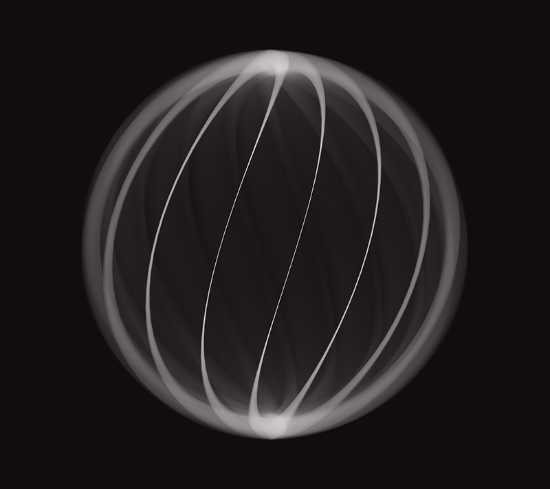
To make things a bit more interesting, let’s twist these vertical lines a bit with this simple change:
为了使事情变得更有趣,让我们通过以下简单更改来扭曲这些垂直线:
let phi1 = (j + i * 0.075) / r2 * Math.PI * 2;
...
let phi2 = (j + (i+1) * 0.075) / r2 * Math.PI * 2;
If we twist the phi angles a bit as we move up the line while we’re constructing it, we’ll end up with:
如果我们在构建直线时在向上移动时稍微扭曲phi角度,最终将得到:
And as a last change, let’s swap the z-axis of both points with the y-axis:
最后,让我们将两个点的z轴与y轴交换:
...
lines.push(
    new Line({
        v1: vec3(x1,z1,y1).multiplyScalar(15),
        v2: vec3(x2,z2,y2).multiplyScalar(15),
        c1: vec3(5,5,5),
        c2: vec3(5,5,5),
    })
);
...
Here’s the full source of createScene.js up to this point.
到目前为止,这是createScene.js的完整源代码。
段平面相交 (Segment-Plane intersections)
Now the fun part begins. To recreate these type of intersections between the lines we just did
现在,有趣的部分开始了。 为了重新创建这些线之间的交点类型
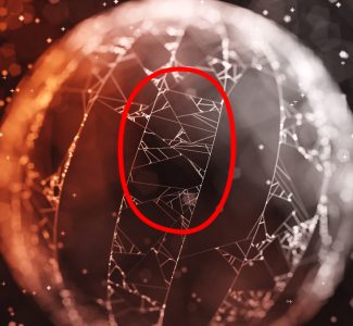
…we’ll need to play a bit with ray-plane intersections. Here’s an overview of what we’ll do:
…我们需要对射线平面相交进行一些操作。 以下是我们的工作概述:
Given the lines we made in our 3D scene, we’re going to create an infinite plane with a random direction and we’ll intersect this plane with all the lines we have in the scene. Then we’ll pick one of these lines intersecting the plane (chosen at random) and we’ll find the closest line to it that is also intersected by the plane.
给定我们在3D场景中制作的直线,我们将创建一个具有随机方向的无限平面,并将该平面与场景中所有的直线相交。 然后,我们选择与平面相交的这些线之一(随机选择),然后找到与该平面相交的最接近的线。
Let’s use a figure to make the example a bit easier to digest:
让我们用一个数字使示例更容易理解:
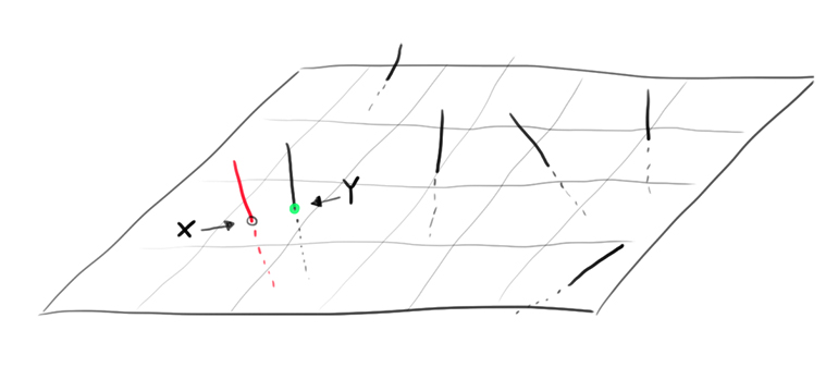
Let’s assume all the segments in the picture are the lines of our scene that intersected the random plane. The red line was chosen randomly out of all the intersected lines. Every line intersects the plane at a specific point in 3D space. Let’s call “x” the point of contact of the red line with the random plane.
假设图片中的所有片段都是场景中与随机平面相交的线。 红线是从所有相交的线中随机选择的。 每条线在3D空间中的特定点与平面相交。 我们将红线与随机平面的接触点称为“ x”。
The next step is to find the closest point to “x”, from all the other contact points of the other lines that were intersected by the plane. In the figure the green point “y” is the closest.
下一步是从与平面相交的其他线的所有其他接触点中找到最接近“ x”的点。 在图中,绿点“ y”是最接近的。
As soon as we have these two points “x” and “y”, we’ll simply create another line connecting them.
一旦有了这两个点“ x”和“ y”,我们将简单地创建另一条连接它们的线。
If we run this process several times (creating a random plane, intersecting our lines, finding the closest point, making a new line) we’ll end up with the result we want. To make it possible, let’s define findIntersectingEdges() as:
如果我们多次运行此过程(创建随机平面,与线相交,找到最接近的点,绘制新线),我们将得到所需的结果。 为了使之成为可能,让我们将findIntersectingEdges()定义为:
function findIntersectingEdges(center, dir) {

    let contactPoints = [];
    for(line of lines) {
        let ires = intersectsPlane(
            center, dir,
            line.v1, line.v2
        );

        if(ires === false) continue;

        contactPoints.push(ires);
    }

    if(contactPoints.length < 2) return;
}
The two parameters of findIntersectingEdges() are the center of the 3D plane and the direction that the plane is facing towards. contactPoints will store all the points of intersection between the lines of our scene and the plane, intersectsPlane() will tell us if a given line intersects a plane. If the returned value ires isn’t undefined, which means there’s a point of intersection stored inside the ires variable, we’ll save the ires variable in the contactPoints array.
findIntersectingEdges()的两个参数是3D平面的中心和该平面所面向的方向。 contactPoints将存储场景线和平面之间的所有交点, intersectsPlane()会告诉我们给定的线是否与平面相交。 如果返回值ires不是未定义的,这意味着在ires变量中存储了一个交点,我们将ires变量保存在contactPoints数组中。
intersectsPlane() is defined as:
intersectsPlane()定义为:
function intersectsPlane(planePoint, planeNormal, linePoint, linePoint2) {

    let lineDirection = new THREE.Vector3(linePoint2.x - linePoint.x, linePoint2.y - linePoint.y, linePoint2.z - linePoint.z);
    let lineLength = lineDirection.length();
    lineDirection.normalize();

    if (planeNormal.dot(lineDirection) === 0) {
        return false;
    }

    let t = (planeNormal.dot(planePoint) - planeNormal.dot(linePoint)) / planeNormal.dot(lineDirection);
    if (t > lineLength) return false;
    if (t < 0) return false;

    let px = linePoint.x + lineDirection.x * t;
    let py = linePoint.y + lineDirection.y * t;
    let pz = linePoint.z + lineDirection.z * t;

    let planeSize = Infinity;
    if(vec3(planePoint.x - px, planePoint.y - py, planePoint.z - pz).length() > planeSize) return false;

    return vec3(px, py, pz);
}
I won’t go over the details of how this function works, if you want to know more check the original version of the function here.
如果您想了解更多信息,请在此处查看该功能的原始版本,我不会详细介绍该功能的工作原理。
Let’s now go to step 2: Picking a random contact point (we’ll call it randCp) and finding its closest neighbor contact point. Append this snippet at the end of findIntersectingEdges():
现在,转到第2步:选择一个随机接触点(我们将其称为randCp )并找到其最近的邻居接触点。 将此代码段附加到findIntersectingEdges()的末尾:
function findIntersectingEdges(center, dir) {
    ...
    ...

    let randCpIndex = Math.floor(rand() * contactPoints.length);
    let randCp = contactPoints[randCpIndex];

    // let's search the closest contact point from randCp
    let minl = Infinity;
    let minI = -1;

    // iterate all contact points
    for(let i = 0; i < contactPoints.length; i++) {
        // skip randCp otherwise the closest contact point to randCp will end up being... randCp!
        if(i === randCpIndex) continue;

        let cp2 = contactPoints[i];

        // 3d point in space of randCp
        let v1 = vec3(randCp.x, randCp.y, randCp.z);
        // 3d point in space of the contact point we're testing for proximity
        let v2 = vec3(cp2.x, cp2.y, cp2.z);

        let sv = vec3(v2.x - v1.x, v2.y - v1.y, v2.z - v1.z);
        // "l" holds the euclidean distance between the two contact points
        let l = sv.length();

        // if "l" is smaller than the minimum distance we've registered so far, store this contact point's index as minI
        if(l < minl) {
            minl = l;
            minI = i;
        }
    }

    let cp1 = contactPoints[randCpIndex];
    let cp2 = contactPoints[minI];

    // let's create a new line out of these two contact points
    lines.push(
        new Line({
            v1: vec3(cp1.x, cp1.y, cp1.z),
            v2: vec3(cp2.x, cp2.y, cp2.z),
            c1: vec3(2,2,2),
            c2: vec3(2,2,2),
        })
    );
}
Now that we have our routine to test intersections against a 3D plane, let’s use it repeatedly against the lines that we already made in the surface of the sphere. Append the following code at the end of computeWeb():
现在我们有了例程来测试3D平面上的相交,让我们针对已经在球体表面上制作的线重复使用它。 在computeWeb()的末尾附加以下代码:
function computeWeb() {

    ...
    ...

    // intersect many 3d planes against all the lines we made so far
    for(let i = 0; i < 4500; i++) {
        let x0 = nrand() * 15;
        let y0 = nrand() * 15;
        let z0 = nrand() * 15;

        // dir will be a random direction in the unit sphere
        let dir = vec3(nrand(), nrand(), nrand()).normalize();
        findIntersectingEdges(vec3(x0, y0, z0), dir);
    }
}
If you followed along, you should get this result
如果您遵循,应该得到这个结果

Click here to see the source up to this point.
单击此处查看到目前为止的资源。
添加火花 (Adding sparkles)
We’re almost done! To make the depth of field effect more prominent we’re going to fill the scene with little sparkles. So, it’s now time to define the last function we were missing:
我们快完成了! 为了使景深效果更加突出,我们将在场景中填充少量闪光。 因此,现在该定义我们缺少的最后一个函数了:
function computeSparkles() {
    for(let i = 0; i < 5500; i++) {
        let v0 = vec3(nrand(), nrand(), nrand()).normalize().multiplyScalar(18 + rand() * 65);

        let c = 1.325 * (0.3 + rand() * 0.7);
        let s = 0.125;

        if(rand() > 0.9) {
            c *= 4;
        }

        lines.push(new Line({
            v1: vec3(v0.x - s, v0.y, v0.z),
            v2: vec3(v0.x + s, v0.y, v0.z),

            c1: vec3(c, c, c),
            c2: vec3(c, c, c),
        }));

        lines.push(new Line({
            v1: vec3(v0.x, v0.y - s, v0.z),
            v2: vec3(v0.x, v0.y + s, v0.z),

            c1: vec3(c, c, c),
            c2: vec3(c, c, c),
        }));
    }
}
Let’s start by explaining this line:
让我们开始解释这一行:
let v0 = vec3(nrand(), nrand(), nrand()).normalize().multiplyScalar(18 + rand() * 65);
令v0 = vec3(nrand(),nrand(),nrand())。normalize()。multiplyScalar(18 + rand()* 65);
Here we’re creating a 3D vector with three random values between -1 and +1. Then, by doing .normalize() we’re making it a “unit vector”, which is a vector whose length is exactly 1.
在这里,我们正在创建一个3D向量,该向量具有介于-1和+1之间的三个随机值。 然后,通过执行.normalize() ,将其设为“单位向量”,即长度恰好为1的向量。
If you drew many points by using this method (choosing three random components between [-1, +1] and then normalizing the vector) you’d notice that all the points you draw end up on the surface of a sphere (which have a radius of exactly one).
如果使用此方法绘制了许多点(在[-1,+1]之间选择三个随机分量,然后对向量进行归一化),您会注意到绘制的所有点最终都在球体的表面上(它们具有一个半径恰好为一)。
Since the sphere we’re drawing in computeWeb() has a radius of exactly 15 units, we want to make sure that all our sparkles don’t end up inside the sphere generated in computeWeb().
由于我们在computeWeb()中绘制的球体的半径正好为15个单位,因此我们要确保所有火花都不会落在computeWeb()生成的球体内。
We can make sure that all points are far enough from the sphere by multiplying each vector component by a scalar that is bigger than the sphere radius with .multiplyScalar(18 … and then adding some randomness to it by adding + rand() * 65.
通过用.multiplyScalar(18…)将每个矢量分量乘以一个比球体半径大的标量,然后通过加上+ rand()* 65为其添加一些随机性,可以确保所有点都距球体足够远。
let c = 1.325 * (0.3 + rand() * 0.7);
令c = 1.325 *(0.3 + rand()* 0.7);
c is a multiplier for the color intensity of the sparkle we’re computing. At a minimum, it will be 1.325 * (0.3), if rand() ends up at the highest possible value, c will be 1.325 * (1).
c是我们正在计算的闪光的颜色强度的乘数。 至少它将是1.325 *(0.3),如果rand()最终以尽可能高的值结束,则c将是1.325 *(1)。
The line if(rand() > 0.9) c *= 4; can be read as “every 10 sparkles, make one whose color intensity is four times bigger than the others”.
该行if(rand()> 0.9)c * = 4; 可以理解为“每10个闪光,使一个颜色强度比其他闪光大四倍”。
The two calls to lines.push() are drawing a horizontal line of size s, and center v0, and a vertical line of size s, and center v0. All the sparkles are in fact little “plus signs”.
对line.push()的两个调用绘制了大小为s的水平线和中心v0 ,以及大小为s的垂直线和中心v0 。 实际上,所有的火花都是很小的“加号”。
And here’s what we have up to this point:
到此为止,我们要做的是:
… and the code for createScene.js
添加灯光和颜色(Adding lights and colors)
The final step to our small journey with Blurry is to change the color of our lines to match the colors of the finished scene.
我们进行模糊之旅的最后一步是更改线条的颜色以匹配最终场景的颜色。
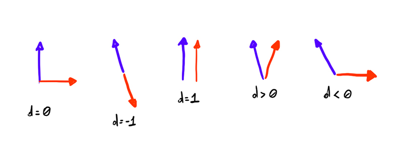
Before we do so, I’ll give a very simplistic explanation of the algebraic operation called “dot product”. If we plot two unit vectors in 3D space, we can measure how “similar” the direction they’re pointing to is.
在我们这样做之前,我将对称为“点积”的代数运算进行非常简单的解释。 如果我们在3D空间中绘制两个单位矢量,则可以测量它们指向的方向有多“相似”。
Two parallel unit vectors will have a dot product of 1 while orthogonal unit vectors will instead have a dot product of 0. Opposite unit vectors will result in a dot product of -1.
两个并行单位向量的点积为1,而正交单位向量的点积为0。相反的单位向量的点积为-1。
Take this picture as a reference for the value of the dot product depending on the two input unit vectors:
将此图片作为点积值的参考,具体取决于两个输入单位向量:
We can use this operation to calculate “how close” two directions are to each other, and we’ll use it to fake diffuse lighting and create the effect that two light sources are lighting up the scene.
我们可以使用此操作来计算两个方向之间的“接近程度”,然后将其用于伪造漫射照明并创建两个光源照亮场景的效果。
Here’s a drawing which will hopefully make it easier to understand what we’ll do:
这是一张希望可以使我们更容易理解的图纸:
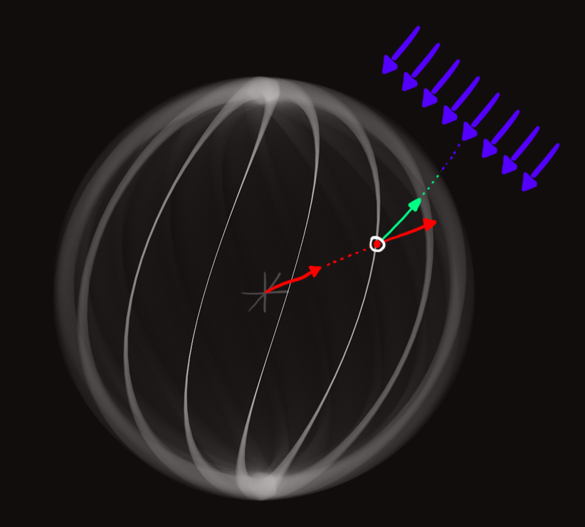
The red and white dot on the surface of the sphere has the red unit vector direction associated with it. Now let’s imagine that the violet vectors represent light emitted from a directional light source, and the green vector is the opposite vector of the violet vector (in algebraic terms the green vector is the negation of the violet vector). If we take the dot product between the red and the green vector, we’ll get an estimate of how much the two vectors point to the same direction. The bigger the value is, the bigger the amount of light received at that point will be. The intuitive reasoning behind this process is essentially to imagine each of the points in our lines as if they were very small planes. If these little planes are facing toward the light source, they’ll absorb and reflect more light from it.
球体表面上的红色和白色点具有与之关联的红色单位矢量方向。 现在让我们想象一下,紫罗兰色矢量代表从定向光源发出的光,绿色矢量是紫罗兰色矢量的相反矢量(按代数形式,绿色矢量是紫罗兰色矢量的取反)。 如果我们取红色和绿色矢量之间的点积,则将获得两个矢量指向同一方向的估计值。 值越大,该点接收的光量越大。 该过程背后的直观推理本质上是将我们直线中的每个点想象成非常小的平面。 如果这些小平面朝向光源,它们将吸收并反射更多的光。
Remember though that the dot operation can also return negative values. We’ll catch that by making sure that the minimum value returned by that function is greater or equal than 0.
但是请记住,点操作也可以返回负值。 我们将通过确保该函数返回的最小值大于或等于0来捕获该错误。
Let’s now code what we said so far with words and define two new global variables just before the definition of createScene():
现在,让我们用单词对到目前为止所说的内容进行编码,并在createScene()定义之前定义两个新的全局变量:
let lightDir0 = vec3(1, 1, 0.2).normalize();
let lightDir1 = vec3(-1, 1, 0.2).normalize();
You can think about both variables as two green vectors in the picture above, pointing to two different directional light sources.
您可以将两个变量都视为上图中的两个绿色矢量,它们指向两个不同的定向光源。
We’ll also create a normal1 variable which will be used as our “red vector” in the picture above and calculate the dot products between normal1 and the two light directions we just added. Each light direction will have a color associated to it. After we calculate with the dot products how much light is reflected from both light directions, we’ll just sum the two colors together (we’ll sum the RGB triplets) and use that as the new color of the line we’ll create.
我们还将创建一个normal1变量,该变量将用作上图中的“红色矢量”,并计算normal1与我们刚刚添加的两个光方向之间的点积。 每个光方向将具有与其关联的颜色。 在使用点积计算出两个方向上反射的光量后,我们将两种颜色加在一起(将RGB三元组相加),并将其用作我们将创建的线条的新颜色。
Lets finally append a new snippet to the end of computeWeb() which will change the color of the lines we computed in the previous steps:
最后,让我们在computeWeb()的末尾添加一个新的代码段,这将更改我们在先前步骤中计算出的行的颜色:
function computeWeb() {
    ...

    // recolor edges
    for(line of lines) {
        let v1 = line.v1;

        // these will be used as the "red vectors" of the previous example
        let normal1 = v1.clone().normalize();

        // lets calculate how much light normal1
        // will get from the "lightDir0" light direction (the white light)
        // we need Math.max( ... , 0.1) to make sure the dot product doesn't get lower than
        // 0.1, this will ensure each point is at least partially lit by a light source and
        // doesn't end up being completely black
        let diffuse0 = Math.max(lightDir0.dot(normal1), 0.1);
        // lets calculate how much light normal1
        // will get from the "lightDir1" light direction (the reddish light)
        let diffuse1 = Math.max(lightDir1.dot(normal1), 0.1);

        let firstColor = [diffuse0, diffuse0, diffuse0];
        let secondColor = [2 * diffuse1, 0.2 * diffuse1, 0];

        // the two colors will represent how much light is received from both light directions,
        // so we'll need to sum them togheter to create the effect that our scene is being lit by two light sources
        let r1 = firstColor[0] + secondColor[0];
        let g1 = firstColor[1] + secondColor[1];
        let b1 = firstColor[2] + secondColor[2];

        let r2 = firstColor[0] + secondColor[0];
        let g2 = firstColor[1] + secondColor[1];
        let b2 = firstColor[2] + secondColor[2];

        line.c1 = vec3(r1, g1, b1);
        line.c2 = vec3(r2, g2, b2);
    }
}
Keep in mind what we’re doing is a very, very simple way to recreate diffuse lighting, and it’s incorrect for many reasons, starting from the fact we’re only considering the first vertex of each line, and assigning the calculated light contribution to both, the first and second vertex of the line, without considering the fact that the second vertex might be very far away from the first vertex, thus ending up with a different normal vector and consequently different light contributions. But we’ll live with this simplification for the purpose of this article.
请记住,我们正在做的是一种非常非常简单的方式来重建漫射光照,并且由于许多原因它是不正确的,这是因为我们只考虑了每条线的第一个顶点,然后将计算出的光贡献分配给线的第一个和第二个顶点,都没有考虑到第二个顶点可能与第一个顶点相距甚远的事实,因此最终以不同的法向矢量和不同的光贡献结束。 但是出于本文的目的,我们将接受这种简化。
Let’s also update the lines created with computeSparkles() to reflect these changes as well:
我们还要更新用computeSparkles()创建的行,以同样反映这些更改:
function computeSparkles() {
    for(let i = 0; i < 5500; i++) {
        let v0 = vec3(nrand(), nrand(), nrand()).normalize().multiplyScalar(18 + rand() * 65);

        let c = 1.325 * (0.3 + rand() * 0.7);
        let s = 0.125;

        if(rand() > 0.9) {
            c *= 4;
        }

        let normal1 = v0.clone().normalize();

        let diffuse0 = Math.max(lightDir0.dot(normal1), 0.1);
        let diffuse1 = Math.max(lightDir1.dot(normal1), 0.1);

        let r = diffuse0 + 2 * diffuse1;
        let g = diffuse0 + 0.2 * diffuse1;
        let b = diffuse0;

        lines.push(new Line({
            v1: vec3(v0.x - s, v0.y, v0.z),
            v2: vec3(v0.x + s, v0.y, v0.z),

            c1: vec3(r * c, g * c, b * c),
            c2: vec3(r * c, g * c, b * c),
        }));

        lines.push(new Line({
            v1: vec3(v0.x, v0.y - s, v0.z),
            v2: vec3(v0.x, v0.y + s, v0.z),

            c1: vec3(r * c, g * c, b * c),
            c2: vec3(r * c, g * c, b * c),
        }));
    }
}
And that’s it!
就是这样!
The scene you’ll end up seeing will be very similar to the one we wanted to recreate at the beginning of the article. The only difference will be that I’m calculating the light contribution for both computeWeb() and computeSparkles() as:
您最终将看到的场景与我们希望在本文开头重新创建的场景非常相似。 唯一的区别是,我要计算的computeWeb()和computeSparkles()的光贡献为:
let diffuse0 = Math.max(lightDir0.dot(normal1) * 3, 0.15);
let diffuse1 = Math.max(lightDir1.dot(normal1) * 2, 0.2 );
Check the full source here or take a look at the live demo.
在此处查看完整源代码或观看现场演示。
最后的话 (Final words)
If you made it this far, you’ll now know how this very simple library works and hopefully you learned a few tricks for your future generative art projects!
如果到此为止,您现在将知道这个非常简单的库的工作原理,并希望您为以后的生成艺术项目学到了一些窍门!
This little project only used lines as primitives, but you can also use textured quads, motion blur, and a custom shader pass that I’ve used recently to recreate volumetric light shafts. Look through the examples in libs/scenes/ if you’re curious to see those features in action.
这个小项目仅将线条用作图元,但是您也可以使用纹理四边形,运动模糊和自定义着色器通道,我最近使用它们来重新创建体积光轴。 如果您想查看这些功能的运行情况,请查看libs / scenes /中的示例。
If you have any question about the library or if you’d like to suggest a feature/change feel free to open an issue in the github repo. I’d love to hear your suggestions!
如果您对库有任何疑问,或者想提出一个功能/更改,请随时在github repo中打开一个问题。 我很想听听您的建议!
unity 粒子 运动模糊


 4132
4132

 被折叠的 条评论
为什么被折叠?
被折叠的 条评论
为什么被折叠?
 到【灌水乐园】发言


