


stm32功耗模式
按功耗由高到低排列,STM32 具有运行、睡眠、停止和待机四种工作模式。上电复位后 STM32处于运行状态时,当内核不需要继续运行,就可以选择进入后面的三种低功耗模式降低功耗,这三种模式中,电源消耗不同、唤醒时间不同、唤醒源不同,用户需要根据应用需求,选择最佳的低功耗模式。三种低功耗的模式说明见下表。
睡眠模式下,任何中断都可以唤醒内核,外部 / 内部高速时钟保持打开,调压器保持打开,因此,内核只要被唤醒,就能马上正常的执行程序(优点:响应速度快;缺点:功耗比较大);
停止模式下,HSE和HSI被关闭,调压器可选开启或低功耗模式(若选为低功耗模式,则还需要加上调压器从低功耗切换至正常模式下的时间),外部中断唤醒内核。当内核被唤醒时,需要重新配置系统时钟使用外部 HSE 且 PLL 正常倍频(System_Init函数),这个过程就会消耗一定时间;否则程序会直接使用 HSI(不倍频) = 8MHz 作为系统时钟,此时系统运行的相当慢,一些对时钟要求较高的函数配置会无法运行(优点:工号较小;缺点:需要重新配置系统时钟,响应速度慢);
待机模式下,整个1.8V供电区域被关闭,调压器被关闭,只能特定方式唤醒。唤醒之后程序从最开始(启动文件)执行(优点:功耗最低;缺点,每次都是复位执行);


低功耗模式的区别
关于睡眠模式 停止模式 待机模式 的区别,可以分析如下代码:
while(1)
  {
		/*********执行任务***************************/
		printf("\r\n STM32正常运行,亮绿灯\r\n");

		LED_GREEN;
		Delay(0x3FFFFF);

		/*****任务执行完毕,进入睡眠降低功耗***********/

		printf("\r\n 进入睡眠模式,按KEY1或KEY2按键可唤醒\r\n");

		//使用红灯指示,进入睡眠状态
		LED_RED;
		//进入睡眠模式
		__WFI();	//WFI指令进入睡眠

		//等待中断唤醒  K1或K2按键中断

		/***被唤醒,亮蓝灯指示***/
		LED_BLUE;
		Delay(0x1FFFFF);

		printf("\r\n 已退出睡眠模式\r\n");
		//继续执行while循环
  }
}
睡眠 模式
当程序上电开始执行时,会一直执行到LED_RED,然后调用__WFI()指令进入睡眠模式,此时,内核停止工作,程序不再往下执行。而当中断来临时,内核被唤醒,程序继续执行while循环,当下一次执行到__WFI()时,再次进入睡眠状态,等待唤醒。
停止 模式
当程序上电开始执行时,会一直执行到LED_RED,然后调用__WFI()指令进入睡眠模式,此时,内核停止工作,程序不再往下执行。而当中断来临时,内核被唤醒,等待系统时钟配置成功(消耗时间),程序继续执行while循环,当下一次执行到__WFI()时,再次进入睡眠状态,等待唤醒。
待机模式
一旦进入待机模式,整个1.8V供电区域(内核 NVIC全部断电),只能通过几种特定的方式唤醒,此时,程序将从头开始执行(从启动文件那里开始执行)。
3种模式的详细描述和寄存器配置
1 睡眠模式(任意中断唤醒:systick中断,串口中断等...)

内核寄存器配置说明如下:

关于立即睡眠和退出后睡眠的区别(中文参考手册):

2 停止模式(外部中断唤醒),开启后会默认使用HSI作为系统时钟,通常我们为确保正常使用,还要重新开启HSE:


相关的寄存器配置:
电源控制寄存器,配置停止模式(正常 or 低功耗):


3 待机模式(WKUP[PA0引脚]、RTC、复位、IWDG看门狗),很类似于直接掉电:

相关的寄存器配置:
电源管理库函数
1 配置PVD检测函数 PWR_PVDLevelConfig ,其实就是写入PWR_CR寄存器的这几位:

标准库函数源码:
/**
  * @brief  Configures the voltage threshold detected by the Power Voltage Detector(PVD).
  * @param  PWR_PVDLevel: specifies the PVD detection level
  *   This parameter can be one of the following values:
  *     @arg PWR_PVDLevel_2V2: PVD detection level set to 2.2V
  *     @arg PWR_PVDLevel_2V3: PVD detection level set to 2.3V
  *     @arg PWR_PVDLevel_2V4: PVD detection level set to 2.4V
  *     @arg PWR_PVDLevel_2V5: PVD detection level set to 2.5V
  *     @arg PWR_PVDLevel_2V6: PVD detection level set to 2.6V
  *     @arg PWR_PVDLevel_2V7: PVD detection level set to 2.7V
  *     @arg PWR_PVDLevel_2V8: PVD detection level set to 2.8V
  *     @arg PWR_PVDLevel_2V9: PVD detection level set to 2.9V
  * @retval None
  */
void PWR_PVDLevelConfig(uint32_t PWR_PVDLevel)
{
  uint32_t tmpreg = 0;
  /* Check the parameters */
  assert_param(IS_PWR_PVD_LEVEL(PWR_PVDLevel));
  tmpreg = PWR->CR;
  /* Clear PLS[7:5] bits */
  tmpreg &= CR_PLS_MASK;
  /* Set PLS[7:5] bits according to PWR_PVDLevel value */
  tmpreg |= PWR_PVDLevel;
  /* Store the new value */
  PWR->CR = tmpreg;
}
2 WFI 与 WFE 命令:
/* ###################  Compiler specific Intrinsics  ########################### */

#if defined ( __CC_ARM   ) /*------------------RealView Compiler -----------------*/
/* ARM armcc specific functions */

#define __enable_fault_irq                __enable_fiq
#define __disable_fault_irq               __disable_fiq

#define __NOP                             __nop
#define __WFI                             __wfi
#define __WFE                             __wfe
#define __SEV                             __sev
#define __ISB()                           __isb(0)
#define __DSB()                           __dsb(0)
#define __DMB()                           __dmb(0)
#define __REV                             __rev
#define __RBIT                            __rbit
#define __LDREXB(ptr)                     ((unsigned char ) __ldrex(ptr))
#define __LDREXH(ptr)                     ((unsigned short) __ldrex(ptr))
#define __LDREXW(ptr)                     ((unsigned int  ) __ldrex(ptr))
#define __STREXB(value, ptr)              __strex(value, ptr)
#define __STREXH(value, ptr)              __strex(value, ptr)
#define __STREXW(value, ptr)              __strex(value, ptr)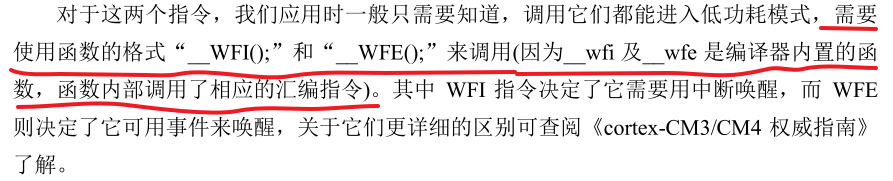
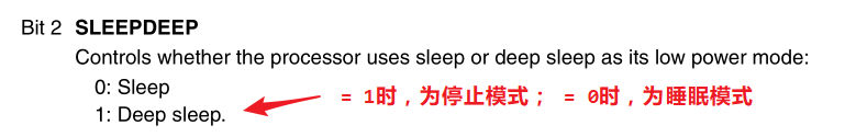
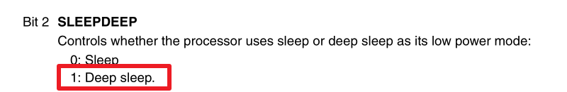
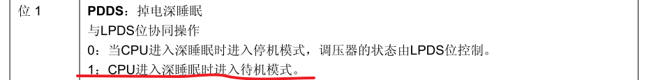
3 进入停止模式
配置PWR_CR寄存器的这两个位,以及SLEEPDEEP位。

/**
  * @brief  Enters STOP mode.
  * @param  PWR_Regulator: specifies the regulator state in STOP mode.
  *   This parameter can be one of the following values:
  *     @arg PWR_Regulator_ON: STOP mode with regulator ON
  *     @arg PWR_Regulator_LowPower: STOP mode with regulator in low power mode
  * @param  PWR_STOPEntry: specifies if STOP mode in entered with WFI or WFE instruction.
  *   This parameter can be one of the following values:
  *     @arg PWR_STOPEntry_WFI: enter STOP mode with WFI instruction
  *     @arg PWR_STOPEntry_WFE: enter STOP mode with WFE instruction
  * @retval None
  */
void PWR_EnterSTOPMode(uint32_t PWR_Regulator, uint8_t PWR_STOPEntry)
{
  uint32_t tmpreg = 0;
  /* Check the parameters */
  assert_param(IS_PWR_REGULATOR(PWR_Regulator));
  assert_param(IS_PWR_STOP_ENTRY(PWR_STOPEntry));

  /* Select the regulator state in STOP mode ---------------------------------*/
  tmpreg = PWR->CR;
  /* Clear PDDS and LPDS bits */
  tmpreg &= CR_DS_MASK;
  /* Set LPDS bit according to PWR_Regulator value */
  tmpreg |= PWR_Regulator;
  /* Store the new value */
  PWR->CR = tmpreg;
  /* Set SLEEPDEEP bit of Cortex System Control Register */
  SCB->SCR |= SCB_SCR_SLEEPDEEP;

  /* Select STOP mode entry --------------------------------------------------*/
  if(PWR_STOPEntry == PWR_STOPEntry_WFI)
  {
    /* Request Wait For Interrupt */
    __WFI();
  }
  else
  {
    /* Request Wait For Event */
    __WFE();
  }

  /* 以下的程序是当重新唤醒时才执行的,清除 SLEEPDEEP 位的状态 */
  SCB->SCR &= (uint32_t)~((uint32_t)SCB_SCR_SLEEPDEEP);
}
在执行最后一句代码前,系统由于调用了__WFI 或 __WFE,已经进入了停止模式,因此,这句清除SLEEPDEEP 位并不会执行。而当内核重新被唤醒时,才会清除SLEEPDEEP位,方便使用。
SCB->SCR &= (uint32_t)~((uint32_t)SCB_SCR_SLEEPDEEP); 
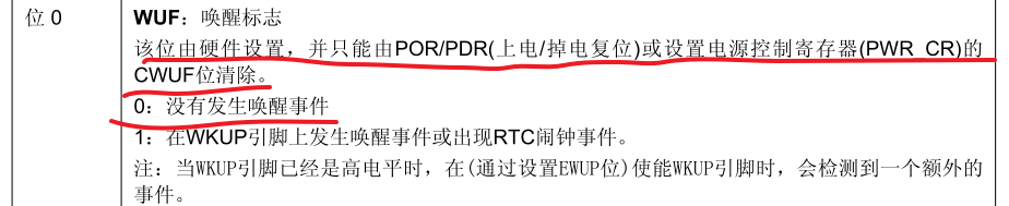
4 进入待机模式(很简单):
/**
  * @brief  Enters STANDBY mode.
  * @param  None
  * @retval None
  */
void PWR_EnterSTANDBYMode(void)
{
  /* Clear Wake-up flag */
  PWR->CR |= PWR_CR_CWUF;
  /* Select STANDBY mode */
  PWR->CR |= PWR_CR_PDDS;
  /* Set SLEEPDEEP bit of Cortex System Control Register */
  SCB->SCR |= SCB_SCR_SLEEPDEEP;
/* This option is used to ensure that store operations are completed */
#if defined ( __CC_ARM   )
  __force_stores();
#endif
  /* Request Wait For Interrupt */
  __WFI();
}
PVD电源监控
实际上,PVD监测的是VDD的电压,也就是stm32的供电电压。当我们调节(降低VDD电压)时,PVD一旦监测到小于设置的阈值,就会产生PVD中断。

标准库中,关于PVD的函数:
1 监测电压等级配置
/**
  * @brief  Configures the voltage threshold detected by the Power Voltage Detector(PVD).
  * @param  PWR_PVDLevel: specifies the PVD detection level
  *   This parameter can be one of the following values:
  *     @arg PWR_PVDLevel_2V2: PVD detection level set to 2.2V
  *     @arg PWR_PVDLevel_2V3: PVD detection level set to 2.3V
  *     @arg PWR_PVDLevel_2V4: PVD detection level set to 2.4V
  *     @arg PWR_PVDLevel_2V5: PVD detection level set to 2.5V
  *     @arg PWR_PVDLevel_2V6: PVD detection level set to 2.6V
  *     @arg PWR_PVDLevel_2V7: PVD detection level set to 2.7V
  *     @arg PWR_PVDLevel_2V8: PVD detection level set to 2.8V
  *     @arg PWR_PVDLevel_2V9: PVD detection level set to 2.9V
  * @retval None
  */
void PWR_PVDLevelConfig(uint32_t PWR_PVDLevel)
{
  uint32_t tmpreg = 0;
  /* Check the parameters */
  assert_param(IS_PWR_PVD_LEVEL(PWR_PVDLevel));
  tmpreg = PWR->CR;
  /* Clear PLS[7:5] bits */
  tmpreg &= CR_PLS_MASK;
  /* Set PLS[7:5] bits according to PWR_PVDLevel value */
  tmpreg |= PWR_PVDLevel;
  /* Store the new value */
  PWR->CR = tmpreg;
}
2 PVD监测使能函数
/**
  * @brief  Enables or disables the Power Voltage Detector(PVD).
  * @param  NewState: new state of the PVD.
  *   This parameter can be: ENABLE or DISABLE.
  * @retval None
  */
void PWR_PVDCmd(FunctionalState NewState)
{
  /* Check the parameters */
  assert_param(IS_FUNCTIONAL_STATE(NewState));
  *(__IO uint32_t *) CR_PVDE_BB = (uint32_t)NewState;
}
整个配置的过程其实很简单:
/**
  * @brief  配置PVD.
  * @param  None
  * @retval None
  */
void PVD_Config(void)
{
  NVIC_InitTypeDef NVIC_InitStructure;
  EXTI_InitTypeDef EXTI_InitStructure;

  /*使能 PWR 时钟 */
  RCC_APB1PeriphClockCmd(RCC_APB1Periph_PWR, ENABLE);

  NVIC_PriorityGroupConfig(NVIC_PriorityGroup_1);

  /* 使能 PVD 中断 */
  NVIC_InitStructure.NVIC_IRQChannel = PVD_IRQn;
  NVIC_InitStructure.NVIC_IRQChannelPreemptionPriority = 0;
  NVIC_InitStructure.NVIC_IRQChannelSubPriority = 0;
  NVIC_InitStructure.NVIC_IRQChannelCmd = ENABLE;
  NVIC_Init(&NVIC_InitStructure);

  /* 配置 EXTI16线(PVD 输出) 来产生上升下降沿中断*/
  EXTI_ClearITPendingBit(EXTI_Line16);
  EXTI_InitStructure.EXTI_Line = EXTI_Line16;
  EXTI_InitStructure.EXTI_Mode = EXTI_Mode_Interrupt;
  EXTI_InitStructure.EXTI_Trigger = EXTI_Trigger_Rising_Falling;
  EXTI_InitStructure.EXTI_LineCmd = ENABLE;
  EXTI_Init(&EXTI_InitStructure);

  /* 配置PVD级别PWR_PVDLevel_2V6 (PVD检测电压的阈值为2.6V,VDD电压低于2.6V时产生PVD中断) */
	/*具体级别根据自己的实际应用要求配置*/
  PWR_PVDLevelConfig(PWR_PVDLevel_2V6);

  /* 使能PVD输出 */
  PWR_PVDCmd(ENABLE);
}
中断服务函数:
/**
  * @brief  PVD中断请求
  * @param  None
  * @retval None
  */
void PVD_IRQHandler(void)
{
		/*检测是否产生了PVD警告信号*/
		if(PWR_GetFlagStatus (PWR_FLAG_PVDO)==SET)
		{
			/* 亮红灯,实际应用中应进入紧急状态处理 */
			LED_RED;

		}
    /* 清除中断信号*/
    EXTI_ClearITPendingBit(EXTI_Line16);

}
然后在主函数 main.c 中进行调用:
int main(void)
{
	LED_GPIO_Config();

	//亮绿灯,表示正常运行
	LED_GREEN;

	//配置PVD,当电压过低时,会进入中断服务函数,亮红灯
	PVD_Config();

  while(1)
  {

		/*正常运行的程序*/

  }
}
怎么进行测试?使用一个可调直流电压源,从5V开始,不断调低开发板的供电电压,观察PVD中断。


 8248
8248


 被折叠的 条评论
为什么被折叠?
被折叠的 条评论
为什么被折叠?
 到【灌水乐园】发言


