


目录
GPIO输出
GPIO(General Purpose Input Output)通用输入输出口
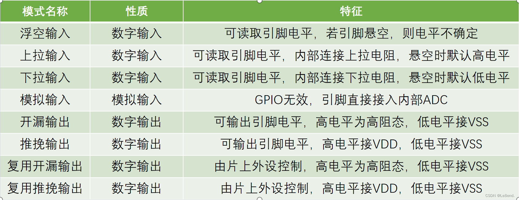
可配置为8种输入输出模式
引脚电平:0V~3.3V,部分引脚可容忍5V
输出模式下可控制端口输出高低电平,用以驱动LED、控制蜂鸣器、模拟通信协议输出时序等
输入模式下可读取端口的高低电平或电压,用于读取按键输入、外接模块电平信号输入、ADC电压采集、模拟通信协议接收数据等
GPIO基本结构
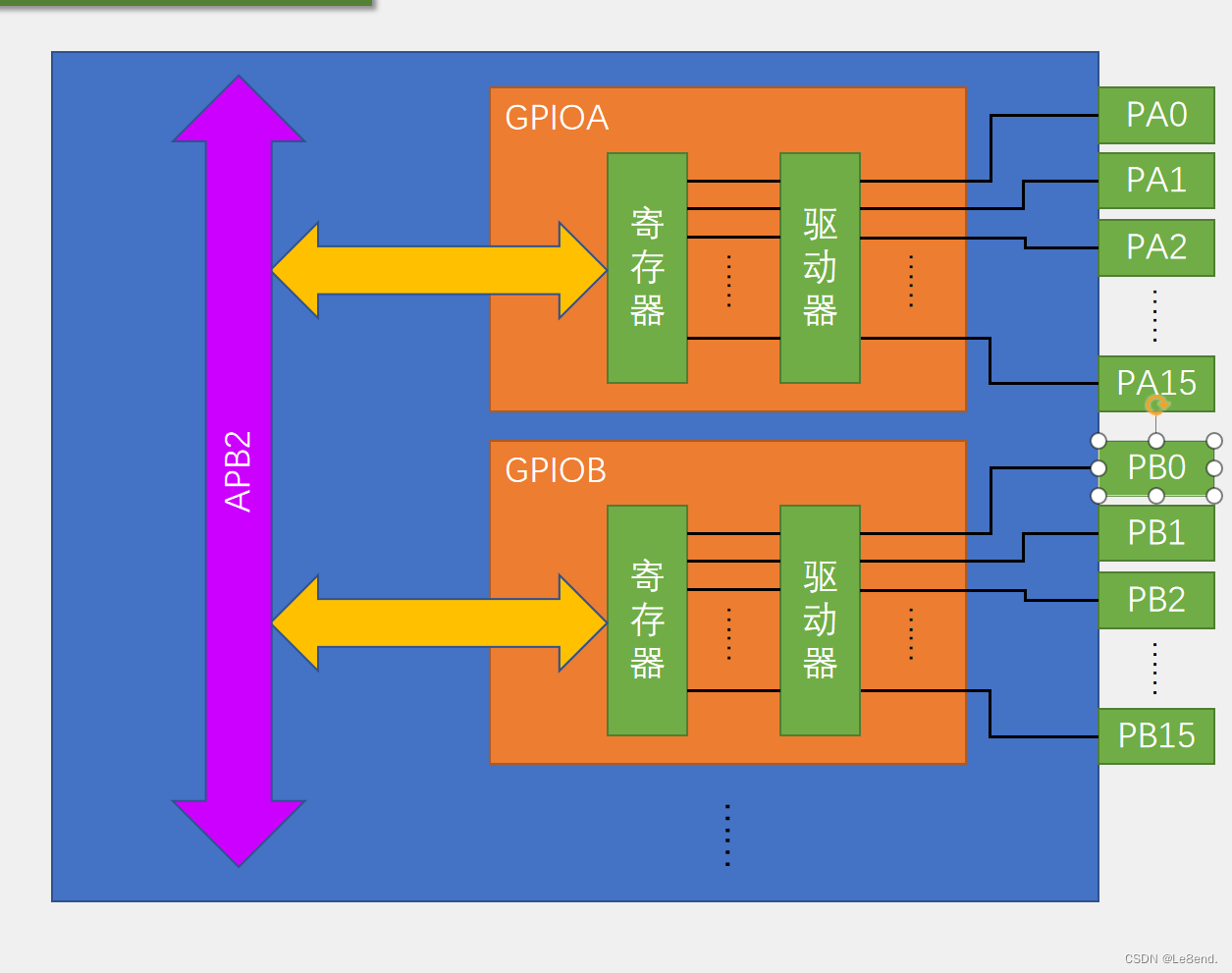
通过配置GPIO的端口配置寄存器,端口可以配置成以下8种模式
LED点灯
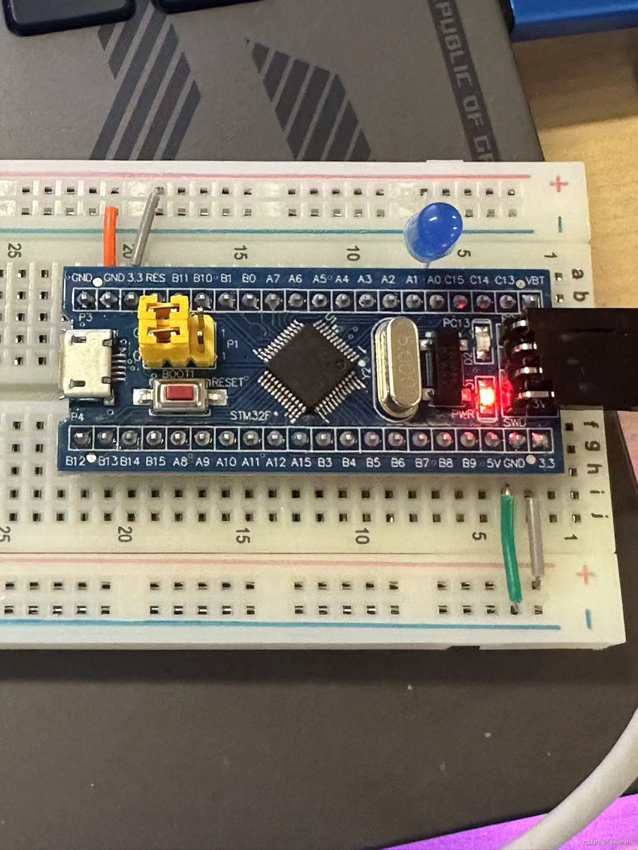
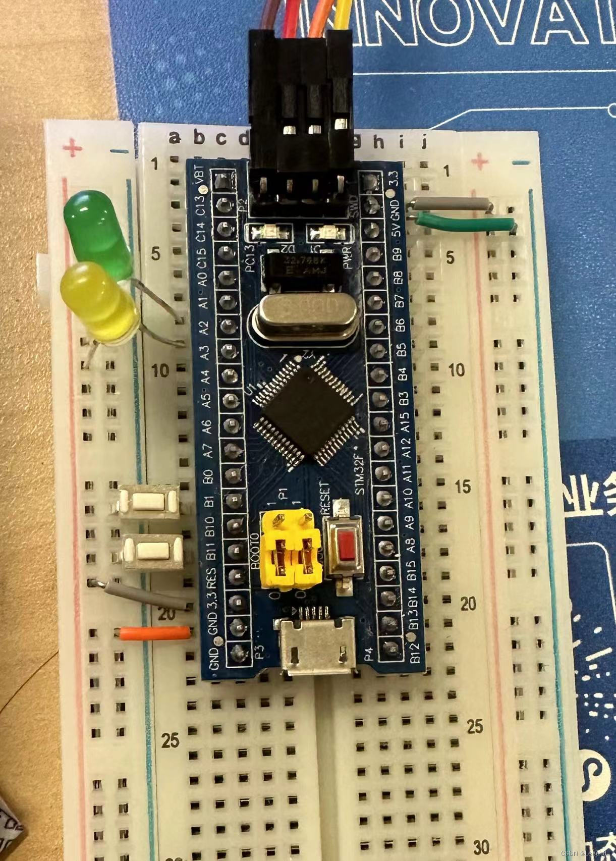
接线
代码
#include "stm32f10x.h"                  // Device header
#include "Delay.h"
int main(void)
{
	RCC_APB2PeriphClockCmd(RCC_APB2Periph_GPIOA,ENABLE);
	GPIO_InitTypeDef GPIO_InitStructure;
	GPIO_InitStructure.GPIO_Mode  = GPIO_Mode_Out_PP;
	GPIO_InitStructure.GPIO_Pin   = GPIO_Pin_0;
	GPIO_InitStructure.GPIO_Speed	= GPIO_Speed_50MHz;
	GPIO_Init(GPIOA,&GPIO_InitStructure);

	while(1)
	{

		GPIO_WriteBit(GPIOA,GPIO_Pin_0,Bit_RESET);
		Delay_ms(100);
		GPIO_WriteBit(GPIOA,GPIO_Pin_0,Bit_SET);
		Delay_ms(100);
	}

}
短脚接负极长脚接PA0——高电平点亮模式
长脚接正极短脚接PA0——低电平点亮模式
GPIO_Mode_Out_PP:模式为推挽模式,该模式下高低电平均有驱动能力,现象为无论led长短接线,led均可闪烁
GPIO_Mode_Out_OD:模式为开漏输出模式,该模式下高电平没有驱动能力,低电平有驱动能力
LED流水灯
#include "stm32f10x.h"                  // Device header
#include "Delay.h"
int main(void)
{
	RCC_APB2PeriphClockCmd(RCC_APB2Periph_GPIOA,ENABLE);
	GPIO_InitTypeDef GPIO_InitStructure;
	GPIO_InitStructure.GPIO_Mode  = GPIO_Mode_Out_PP;
	GPIO_InitStructure.GPIO_Pin   = GPIO_Pin_All;
	GPIO_InitStructure.GPIO_Speed	= GPIO_Speed_50MHz;
	GPIO_Init(GPIOA,&GPIO_InitStructure);

	while(1)
	{

		GPIO_Write(GPIOA,~0x0001);
		Delay_ms(500);
		GPIO_Write(GPIOA,~0x0002);
		Delay_ms(500);
		GPIO_Write(GPIOA,~0x0004);
		Delay_ms(500);
		GPIO_Write(GPIOA,~0x0008);
		Delay_ms(500);
		GPIO_Write(GPIOA,~0x0010);
		Delay_ms(500);
		GPIO_Write(GPIOA,~0x0020);
		Delay_ms(500);
		GPIO_Write(GPIOA,~0x0040);
		Delay_ms(500);
		GPIO_Write(GPIOA,~0x0080);
		Delay_ms(500);

	}

}
蜂鸣器
接线
 代码
代码
#include "stm32f10x.h"                  // Device header
#include "Delay.h"
int main(void)
{
	RCC_APB2PeriphClockCmd(RCC_APB2Periph_GPIOB,ENABLE);
	GPIO_InitTypeDef GPIO_InitStructure;
	GPIO_InitStructure.GPIO_Mode  = GPIO_Mode_Out_PP;
	GPIO_InitStructure.GPIO_Pin   = GPIO_Pin_12;
	GPIO_InitStructure.GPIO_Speed	= GPIO_Speed_50MHz;
	GPIO_Init(GPIOB,&GPIO_InitStructure);

	while(1)
	{

		GPIO_WriteBit(GPIOB,GPIO_Pin_12,Bit_RESET);
		Delay_ms(100);
		GPIO_WriteBit(GPIOB,GPIO_Pin_12,Bit_SET);
		Delay_ms(100);
	}

}
GPIO输入
按键
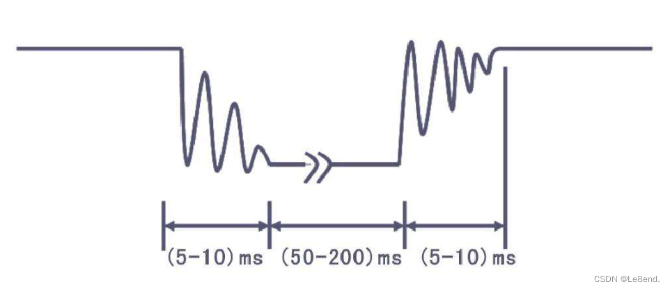
按键:常见的输入设备,按下导通,松手断开
按键抖动:由于按键内部使用的是机械式弹簧片来进行通断的,所以在按下和松手的瞬间会伴随有一连串的抖动
传感器模块
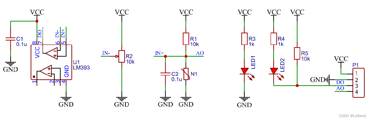
传感器模块:传感器元件(光敏电阻/热敏电阻/红外接收管等)的电阻会随外界模拟量的变化而变化,通过与定值电阻分压即可得到模拟电压输出,再通过电压比较器进行二值化即可得到数字电压输出
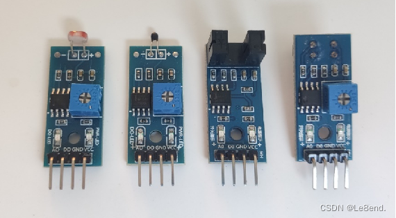
此部分我我不懂,还是学了电路什么的再回来回顾吧。。。
硬件电路
此部分我我不懂,还是学了电路什么的再回来回顾吧。。。、
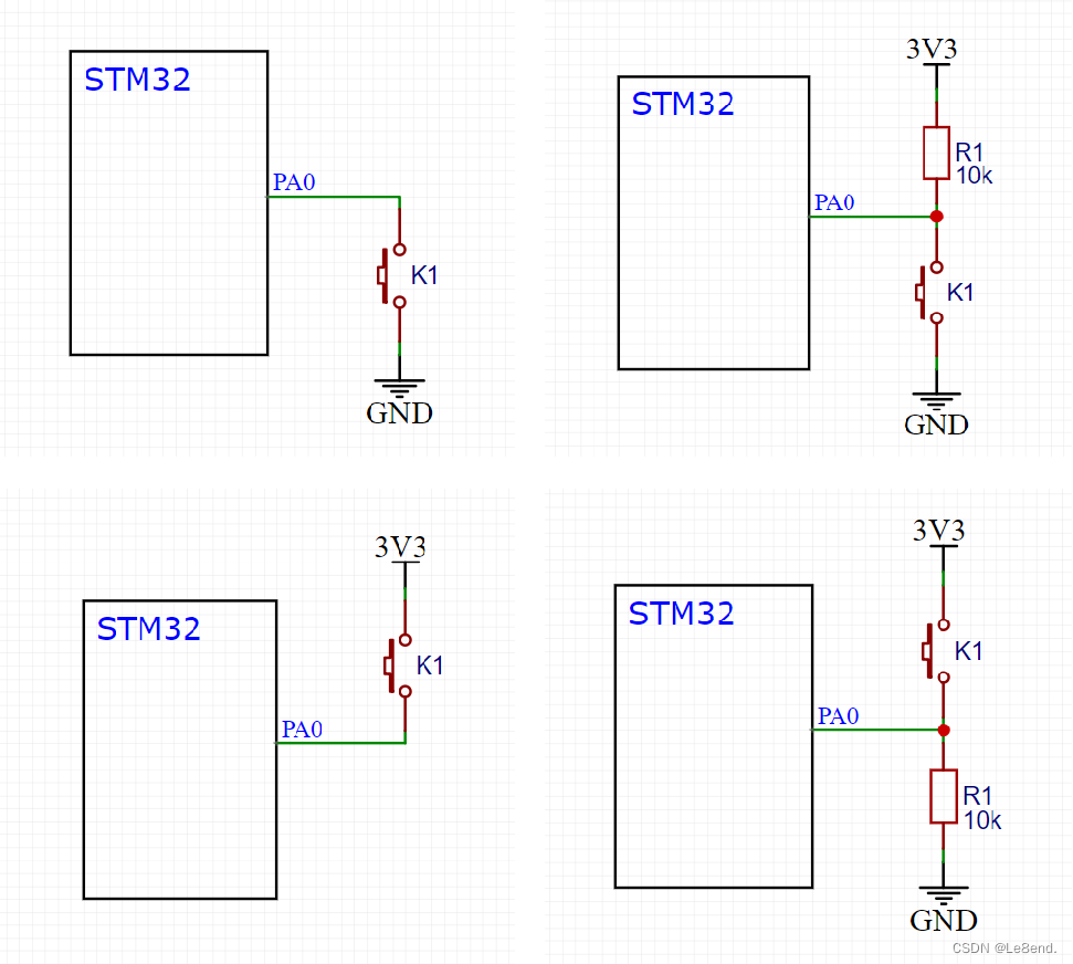
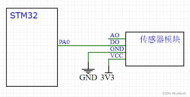
接线
c语言数据类型

单片机中int long都是32位和c语言有所区别。
按键控制led代码
led模块
#include "stm32f10x.h"                  // Device header
void led_init(void)
{
	RCC_APB2PeriphClockCmd(RCC_APB2Periph_GPIOA ,ENABLE);
	GPIO_InitTypeDef GPIO_InitSturcture;
	GPIO_InitSturcture.GPIO_Mode=GPIO_Mode_Out_PP;//GPIO推挽输出
	GPIO_InitSturcture.GPIO_Pin=GPIO_Pin_1|GPIO_Pin_2;
	GPIO_InitSturcture.GPIO_Speed=GPIO_Speed_50MHz;
	GPIO_Init(GPIOA,&GPIO_InitSturcture);//将PA1和PA2引脚初始化为推挽输出
	GPIO_SetBits(GPIOA,GPIO_Pin_1|GPIO_Pin_2);//设置PA1和PA2引脚为高电平
}

void led1_on(void)
{
	GPIO_SetBits(GPIOA,GPIO_Pin_1);//设置PA1引脚为低电平

}

void led1_off(void)
{

	GPIO_ResetBits(GPIOA,GPIO_Pin_1);//设置PA1引脚为高电平

}
void led2_on(void)
{
	GPIO_SetBits(GPIOA,GPIO_Pin_2);//设置PA2引脚为低电平

}

void led2_off(void)
{

	GPIO_ResetBits(GPIOA,GPIO_Pin_2);//设置PA1引脚为高电平

}
void led1_turn(void)//实现翻转
{
	if(GPIO_ReadOutputDataBit(GPIOA,GPIO_Pin_1)==0)//读取端口输出状态
	{
		GPIO_SetBits (GPIOA ,GPIO_Pin_1 );//置1
	}
	else
	{
		GPIO_ResetBits (GPIOA ,GPIO_Pin_1 );//置0
	}
}

void led2_turn(void)//实现翻转
{
	if(GPIO_ReadOutputDataBit(GPIOA,GPIO_Pin_2)==0)//读取端口输出状态
	{
		GPIO_SetBits (GPIOA ,GPIO_Pin_2 );//置1
	}
	else
	{
		GPIO_ResetBits (GPIOA ,GPIO_Pin_2 );//置0
	}
}
按键模块
#include "stm32f10x.h"                  // Device header
#include "Delay.h"

void key_init(void)//按键初始化
{
	RCC_APB2PeriphClockCmd(RCC_APB2Periph_GPIOB ,ENABLE);//开启GPIOB的时钟
	/*GPIO 初始化*/
	GPIO_InitTypeDef GPIO_InitStructure;
	GPIO_InitStructure.GPIO_Mode=GPIO_Mode_IPU ;//GPIO上拉输入模式
	GPIO_InitStructure.GPIO_Pin=GPIO_Pin_1|GPIO_Pin_11;
	GPIO_InitStructure.GPIO_Speed =GPIO_Speed_50MHz;
	GPIO_Init(GPIOB ,&GPIO_InitStructure);//将PB1和PB11引脚初始化为上拉输入

}
uint8_t key_getnum(void)
{
	uint8_t keynum=0;//定义变量,默认值为0

	if(GPIO_ReadInputDataBit(GPIOB ,GPIO_Pin_1)==0)//读PB1输入寄存器的状态,如果为0,则代表按键1按下
		{
		Delay_ms (20);//消除抖动
		while(GPIO_ReadInputDataBit(GPIOB ,GPIO_Pin_1)==0);//检测是否松开
		Delay_ms (20);//消除抖动
		keynum=1;//置1
		}
		if(GPIO_ReadInputDataBit(GPIOB ,GPIO_Pin_11)==0)
		{
		Delay_ms (20);
		while(GPIO_ReadInputDataBit(GPIOB ,GPIO_Pin_11)==0);
		Delay_ms (20);
		keynum=2;
		}
	return keynum;

}
主函数
#include "stm32f10x.h"                  // Device header
#include "Delay.h"
#include "LED.h"
#include "key.h"

uint8_t keynum;
int main(void)
{
	led_init();//led初始化
	key_init();//按键初始化
	while(1)
	{
		keynum=key_getnum();//获取key的状态
		if(keynum ==1)
		{
			led1_turn();

	  }
		if(keynum==2)
		{
			led2_turn();
		}
	}

}
光敏控制蜂鸣器
光敏模块
#include "stm32f10x.h"                  // Device header

void lightsensor_init(void)
{

	RCC_APB2PeriphClockCmd(RCC_APB2Periph_GPIOB ,ENABLE);
	GPIO_InitTypeDef GPIO_InitSturcture;
	GPIO_InitSturcture.GPIO_Mode=GPIO_Mode_IPU;
	GPIO_InitSturcture.GPIO_Pin=GPIO_Pin_13;
	GPIO_InitSturcture.GPIO_Speed=GPIO_Speed_50MHz;
	GPIO_Init(GPIOB,&GPIO_InitSturcture);


}
uint8_t lightsensor_get(void)
{
	return GPIO_ReadInputDataBit(GPIOB ,GPIO_Pin_13);
}
蜂鸣器模块
#include "stm32f10x.h"                  // Device header
void buzzer_init(void)
{
	RCC_APB2PeriphClockCmd(RCC_APB2Periph_GPIOB ,ENABLE);//开启GPIOB的时钟
	GPIO_InitTypeDef GPIO_InitSturcture;
	GPIO_InitSturcture.GPIO_Mode=GPIO_Mode_Out_PP;//将PB12引脚初始化为推挽输出
	GPIO_InitSturcture.GPIO_Pin=GPIO_Pin_12;
	GPIO_InitSturcture.GPIO_Speed=GPIO_Speed_50MHz;
	GPIO_Init(GPIOB,&GPIO_InitSturcture);


	GPIO_SetBits(GPIOB,GPIO_Pin_12);//设置PB12引脚为高电平
}

void buzzer_on(void)
{
	GPIO_ResetBits(GPIOB,GPIO_Pin_12);//设置PB12引脚为低电平
}

void buzzer_off(void)
{
	GPIO_SetBits(GPIOB,GPIO_Pin_12);//设置PB12引脚为高电平
}
void buzzer_turn(void)//实现翻转
{
	if(GPIO_ReadOutputDataBit(GPIOB,GPIO_Pin_12)==0)//读取端口输出状态
	{
		GPIO_SetBits (GPIOB ,GPIO_Pin_12 );//置1
	}
	else
	{
		GPIO_ResetBits (GPIOB ,GPIO_Pin_12 );//置0
	}
}
注意!!! 这其中的buzzer_turn一定要写,而且一定要写对,反反复复的核实。
buzzer_turn的作用是在蜂鸣器为0触发的时候,触发完成后使蜂鸣器置1,暂停触发。这样才会使得buzzer不一直触发!!!
主函数
#include "stm32f10x.h"                  // Device header
#include "Delay.h"
#include "LED.h"
#include "key.h"
#include "Buzzer.h"
#include "lightsensor.h"
int main(void)
{
	lightsensor_init();
	buzzer_init();
	while(1)
	{
		if(lightsensor_get ()==1)
		{
			buzzer_on();
		}
		else
		{
			buzzer_off();
		}
	}

}
总结
1.学会各种模块函数的封装,将最重要的判断什么的放在main函数中。
2.学会注释,不仅仅使得别人能更好的看懂自己的代码,也让自己在以后更好复习,以及代码调试过程中更方便的找到错误
3.GPIO的学习,主要是学习各种GPIO的配置,给GPIO口高低电频以及判断模块的电频触发,学习完电路以及数模电之后应该可以有一个更深的影响。


 30万+
30万+

 被折叠的 条评论
为什么被折叠?
被折叠的 条评论
为什么被折叠?
 到【灌水乐园】发言


