


提示:文章写完后,目录可以自动生成,如何生成可参考右边的帮助文档
文章目录
前言
网上有关有AX58100的相关文章少之又少,只能通过其他ethercat的相关芯片来进行学习等。特此记录学习防止忘记等。本文章主要是Ethercat从站的配置等,主要是实现上位机可以识别。本文章主要是完成步骤的实现,原理相关自行了解。
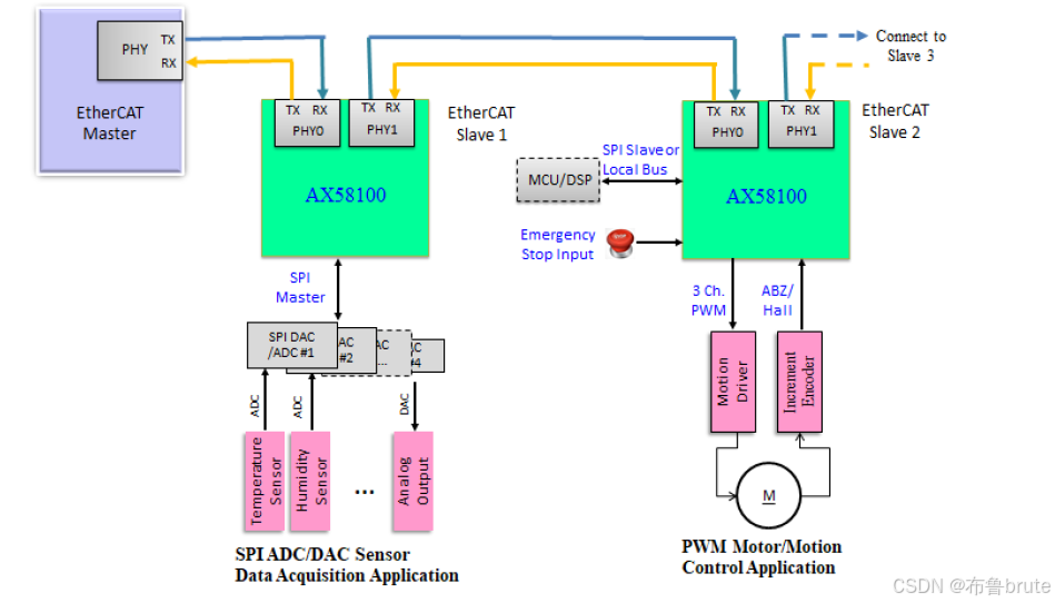
一、项目简介
本项目主站为Twincat3来进行控制,从站为AX58100和stm32f103VBT6的一体板来实现。利用cubemx平台和ssc tool生成的相关代码来进行完成。
二、整体开发流程
1.淘宝购买了相关学习板,得到相关资料和协议文章。
2.根据项目构建需要的xml文件,上位机采用TwinCAT3,进行EEPROM的烧录等。
3.根据学习板的资料和相关群聊的沟通来实现文章。
三、CUBEMX的配置
1.设置时钟
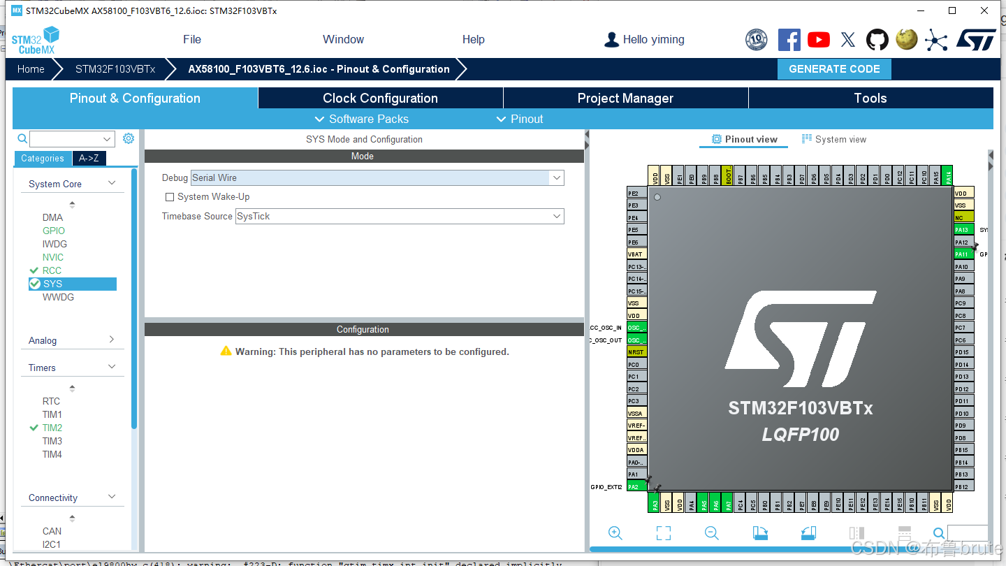
点击SYS→DEBUG选择serial wire
2.RCC设置
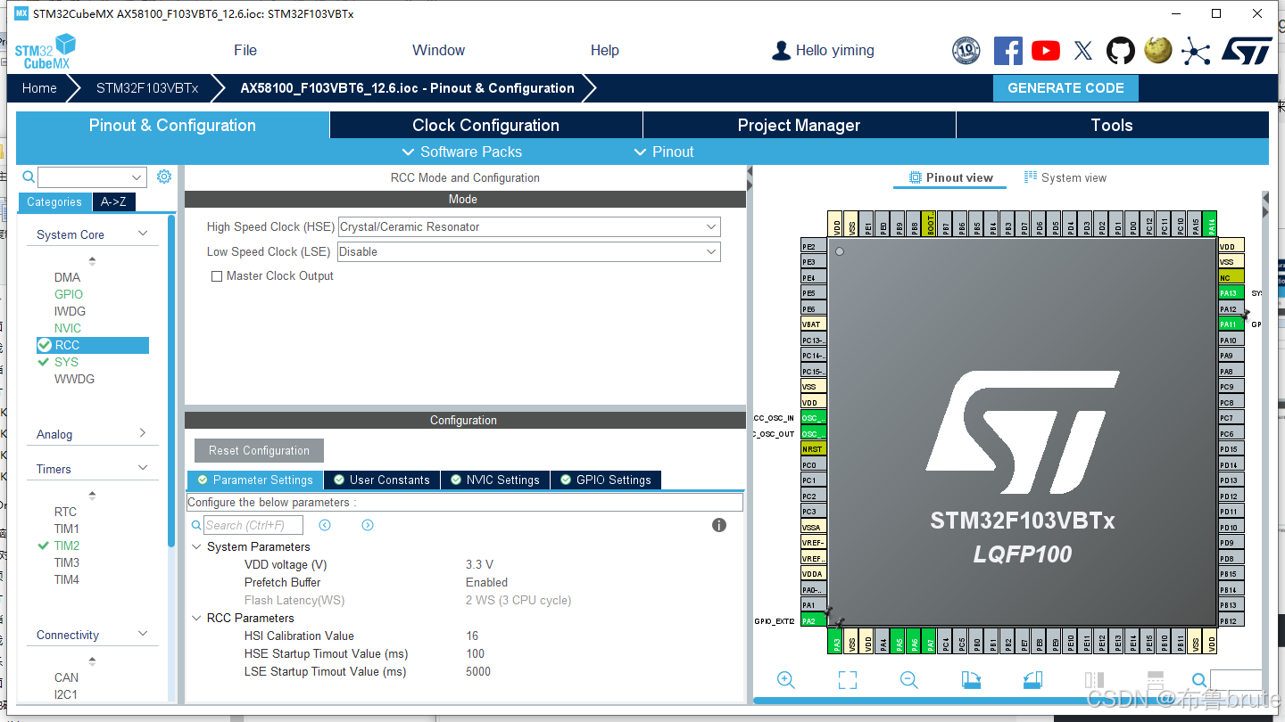
点击RCC→选择外部时钟,选择crystal/ceramic resonator
3.时钟树

点击Clock Configuration,配置如图。
4.定时器配置
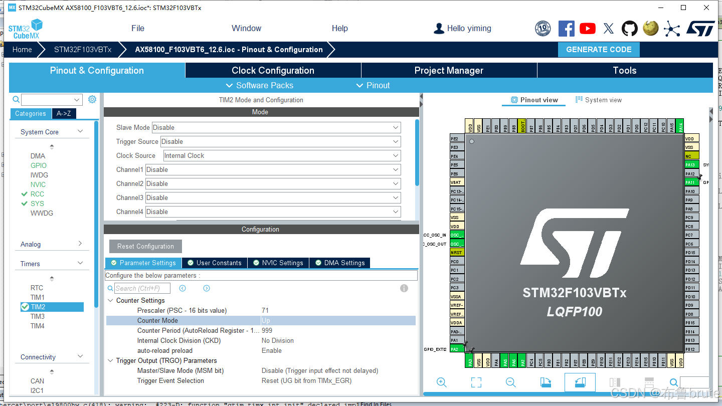
定时器配置如图,
5.SPI设置
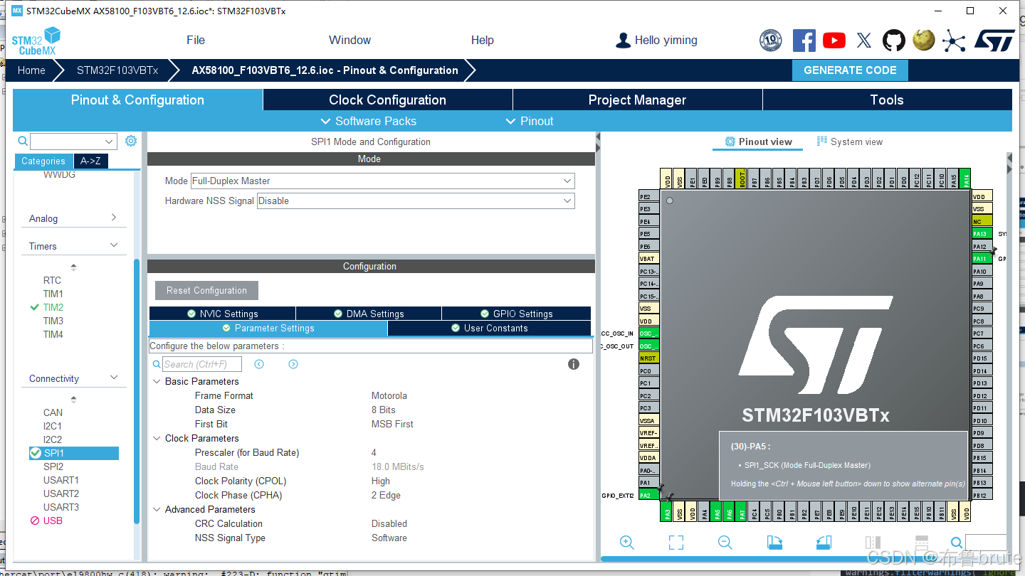
SPI配置选择SPI1来使用,需要使用CS片选,为PA4,这里不做初始化,直接加到程序中。
6.GPIO配置及其外部中断
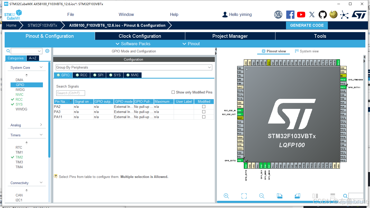
这里选择SYNC1,SYNC0,IRQ…这里和其余教程不同,为了方便ethercat的协议,我直接复制之前的代码进行初始化,生成的直接屏蔽掉。gpio改成如下
更换代码(示例):
gpio.c
/* USER CODE BEGIN 2 */
void IRQ_INT_Init(void)
{
		GPIO_InitTypeDef gpio_init_struct;

    IRQ_INT_GPIO_CLK_ENABLE();
		gpio_init_struct.Pin = IRQ_INT_GPIO_PIN;
    gpio_init_struct.Mode = GPIO_MODE_IT_FALLING;
    gpio_init_struct.Pull = GPIO_PULLUP;
    HAL_GPIO_Init(IRQ_INT_GPIO_PORT, &gpio_init_struct);

		HAL_NVIC_SetPriority(IRQ_INT_IRQn, 0, 0);
    HAL_NVIC_EnableIRQ(IRQ_INT_IRQn);
}

void SYNC1_INT_Init(void)
{
		GPIO_InitTypeDef gpio_init_struct;

    SYNC1_INT_GPIO_CLK_ENABLE();
		gpio_init_struct.Pin = SYNC1_INT_GPIO_PIN;
    gpio_init_struct.Mode = GPIO_MODE_IT_FALLING;
    gpio_init_struct.Pull = GPIO_PULLUP;
    HAL_GPIO_Init(SYNC1_INT_GPIO_PORT, &gpio_init_struct);

		HAL_NVIC_SetPriority(SYNC1_INT_IRQn, 1, 2);
    HAL_NVIC_EnableIRQ(SYNC1_INT_IRQn);
}

void SYNC0_INT_Init(void)
{
		GPIO_InitTypeDef gpio_init_struct;

    SYNC0_INT_GPIO_CLK_ENABLE();
		gpio_init_struct.Pin = SYNC0_INT_GPIO_PIN;
    gpio_init_struct.Mode = GPIO_MODE_IT_FALLING;
    gpio_init_struct.Pull = GPIO_PULLUP;
    HAL_GPIO_Init(SYNC0_INT_GPIO_PORT, &gpio_init_struct);

		HAL_NVIC_SetPriority(SYNC0_INT_IRQn, 1, 1);
    HAL_NVIC_EnableIRQ(SYNC0_INT_IRQn);
}

void EscIntr_Init(void)
{
    GPIO_InitTypeDef gpio_init_struct;

    IRQ_INT_GPIO_CLK_ENABLE();
    SYNC0_INT_GPIO_CLK_ENABLE();
    SYNC1_INT_GPIO_CLK_ENABLE();

    gpio_init_struct.Pin = IRQ_INT_GPIO_PIN;
    gpio_init_struct.Mode = GPIO_MODE_IT_FALLING;
    gpio_init_struct.Pull = GPIO_PULLUP;
    HAL_GPIO_Init(IRQ_INT_GPIO_PORT, &gpio_init_struct);

    gpio_init_struct.Pin = SYNC0_INT_GPIO_PIN;
    gpio_init_struct.Mode = GPIO_MODE_IT_FALLING;
    gpio_init_struct.Pull = GPIO_PULLUP;
    HAL_GPIO_Init(SYNC0_INT_GPIO_PORT, &gpio_init_struct);

    gpio_init_struct.Pin = SYNC1_INT_GPIO_PIN;
    gpio_init_struct.Mode = GPIO_MODE_IT_FALLING;
    gpio_init_struct.Pull = GPIO_PULLUP;
    HAL_GPIO_Init(SYNC1_INT_GPIO_PORT, &gpio_init_struct);

    HAL_NVIC_SetPriority(IRQ_INT_IRQn, 0, 0);
    HAL_NVIC_EnableIRQ(IRQ_INT_IRQn);

    HAL_NVIC_SetPriority(SYNC0_INT_IRQn, 1, 1);
    HAL_NVIC_EnableIRQ(SYNC0_INT_IRQn);

    HAL_NVIC_SetPriority(SYNC1_INT_IRQn, 1, 2);
    HAL_NVIC_EnableIRQ(SYNC1_INT_IRQn);
}

/* USER CODE END 2 */
7.中断配置
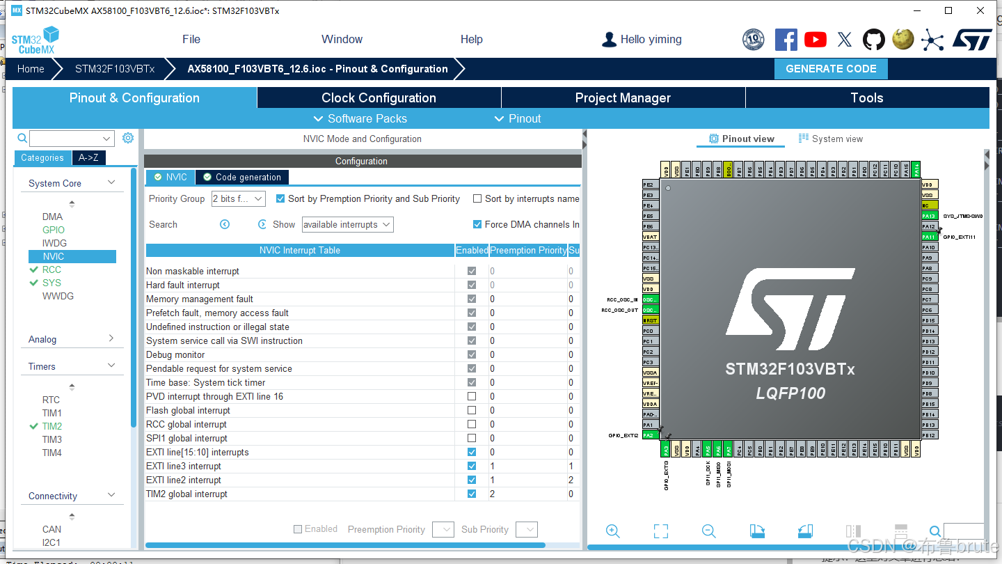
中断优先级配置如图
8.程序生成
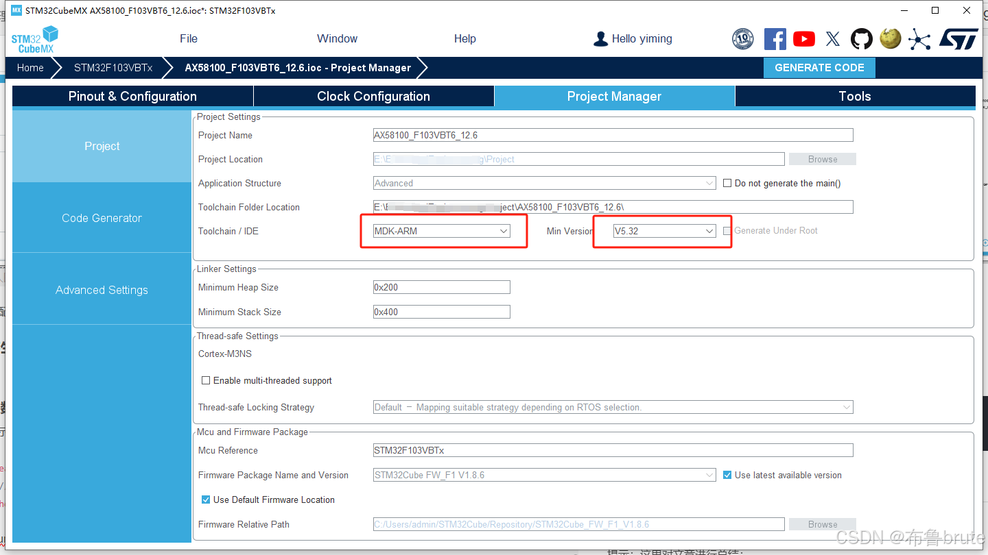
注意生成的程序等。
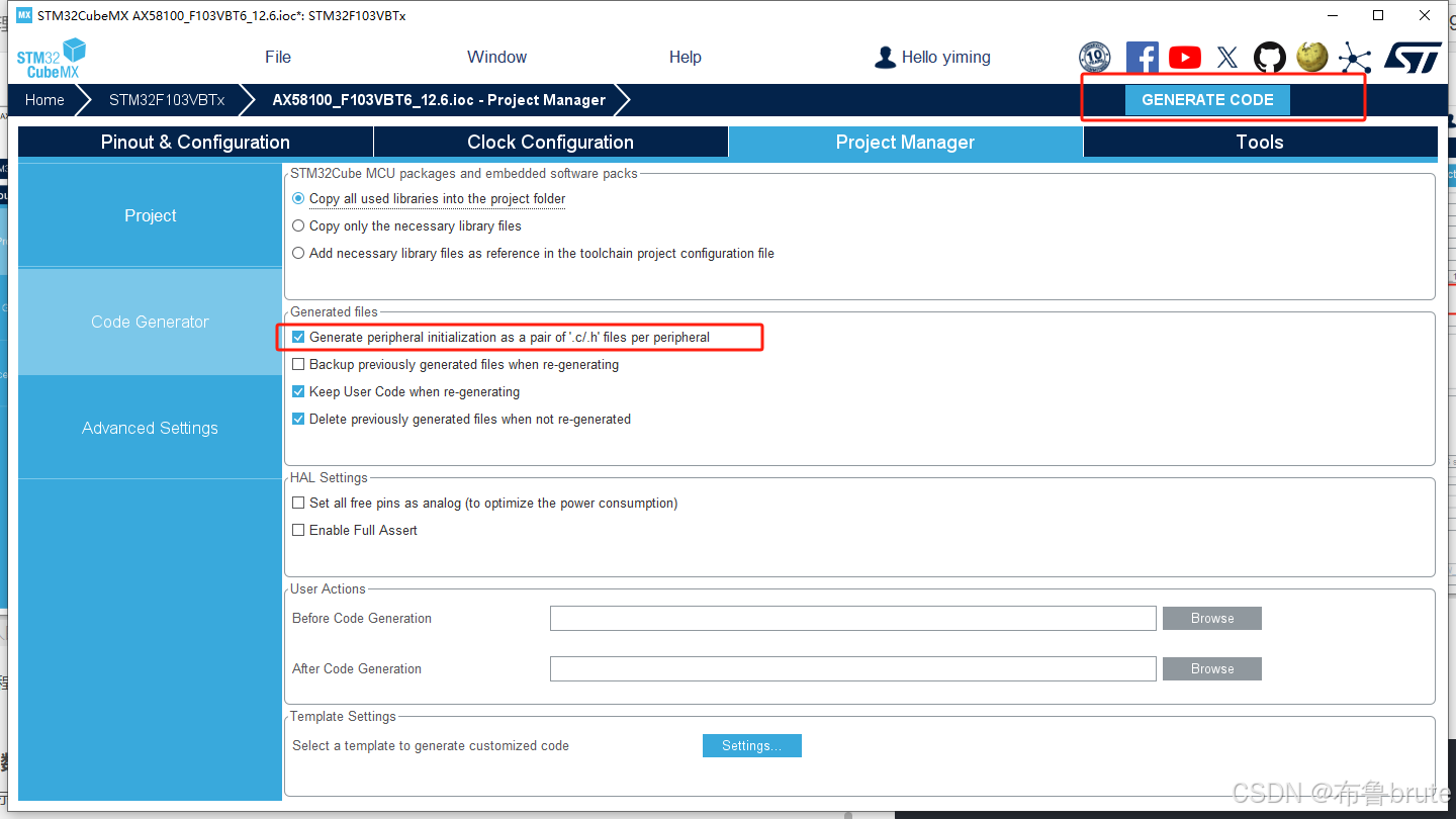
勾选生成c/h文件方便修改,不生成也可以。
四.keil编辑
打开文件直接添加ethercat相关协议,这个协议基本上是通用的,也可以自己去SSC TOOL生成自己需要的。
1.目录添加如下
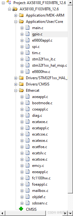
添加好相关文件后,开始我们的代码移植之旅。
main.c:
/* USER CODE END Header */
/* Includes ------------------------------------------------------------------*/
#include "main.h"
#include "spi.h"
#include "tim.h"
#include "gpio.h"
/* USER CODE BEGIN Includes */
#include "el9800appl.h"

void SystemClock_Config(void);

int main(void)
{
  HAL_Init();
  /* Configure the system clock */
  SystemClock_Config();
  /* Initialize all configured peripherals */
//  MX_GPIO_Init();  //这些初始化在EcarMain();进行
//  MX_SPI1_Init();
//  MX_TIM2_Init();
  /* USER CODE BEGIN 2 */
	EcatMain();
  /* USER CODE END 2 */
  /* USER CODE BEGIN WHILE */
  while (1)
  {
  }
  /* USER CODE END 3 */
}
void SystemClock_Config(void)
{
  RCC_OscInitTypeDef RCC_OscInitStruct = {0};
  RCC_ClkInitTypeDef RCC_ClkInitStruct = {0};
  /** Initializes the RCC Oscillators according to the specified parameters
  * in the RCC_OscInitTypeDef structure.
  */
  RCC_OscInitStruct.OscillatorType = RCC_OSCILLATORTYPE_HSE;
  RCC_OscInitStruct.HSEState = RCC_HSE_ON;
  RCC_OscInitStruct.HSEPredivValue = RCC_HSE_PREDIV_DIV1;
  RCC_OscInitStruct.HSIState = RCC_HSI_ON;
  RCC_OscInitStruct.PLL.PLLState = RCC_PLL_ON;
  RCC_OscInitStruct.PLL.PLLSource = RCC_PLLSOURCE_HSE;
  RCC_OscInitStruct.PLL.PLLMUL = RCC_PLL_MUL9;
  if (HAL_RCC_OscConfig(&RCC_OscInitStruct) != HAL_OK)
  {
    Error_Handler();
  }
  /** Initializes the CPU, AHB and APB buses clocks
  */
  RCC_ClkInitStruct.ClockType = RCC_CLOCKTYPE_HCLK|RCC_CLOCKTYPE_SYSCLK
                              |RCC_CLOCKTYPE_PCLK1|RCC_CLOCKTYPE_PCLK2;
  RCC_ClkInitStruct.SYSCLKSource = RCC_SYSCLKSOURCE_PLLCLK;
  RCC_ClkInitStruct.AHBCLKDivider = RCC_SYSCLK_DIV1;
  RCC_ClkInitStruct.APB1CLKDivider = RCC_HCLK_DIV2;
  RCC_ClkInitStruct.APB2CLKDivider = RCC_HCLK_DIV1;

  if (HAL_RCC_ClockConfig(&RCC_ClkInitStruct, FLASH_LATENCY_2) != HAL_OK)
  {
    Error_Handler();
  }
}
void Error_Handler(void)
{
  /* USER CODE BEGIN Error_Handler_Debug */
  /* User can add his own implementation to report the HAL error return state */
  __disable_irq();
  while (1)
  {
  }
  /* USER CODE END Error_Handler_Debug */
}
#ifdef  USE_FULL_ASSERT
void assert_failed(uint8_t *file, uint32_t line)
{
}
#endif /* USE_FULL_ASSERT */
此处修改主要就是将初始化注释掉,因为是在EcatMain()中进行的。
main.h:
#ifndef __MAIN_H
#define __MAIN_H

#ifdef __cplusplus
extern "C" {
#endif
/* Includes ------------------------------------------------------------------*/
#include "stm32f1xx_hal.h"
void Error_Handler(void);
#ifdef __cplusplus
}
#endif
#endif /* __MAIN_H */
gpio.c:
#include "gpio.h"
//void MX_GPIO_Init(void)
//{

//  GPIO_InitTypeDef GPIO_InitStruct = {0};

//  /* GPIO Ports Clock Enable */
//  __HAL_RCC_GPIOA_CLK_ENABLE();

//  /*Configure GPIO pins : PA2 PA3 PA11 */
//  GPIO_InitStruct.Pin = GPIO_PIN_2|GPIO_PIN_3|GPIO_PIN_11;
//  GPIO_InitStruct.Mode = GPIO_MODE_IT_RISING;
//  GPIO_InitStruct.Pull = GPIO_NOPULL;
//  HAL_GPIO_Init(GPIOA, &GPIO_InitStruct);

//  /* EXTI interrupt init*/
//  HAL_NVIC_SetPriority(EXTI2_IRQn, 1, 2);
//  HAL_NVIC_EnableIRQ(EXTI2_IRQn);

//  HAL_NVIC_SetPriority(EXTI3_IRQn, 1, 1);
//  HAL_NVIC_EnableIRQ(EXTI3_IRQn);

//  HAL_NVIC_SetPriority(EXTI15_10_IRQn, 0, 0);
//  HAL_NVIC_EnableIRQ(EXTI15_10_IRQn);

//}

/* USER CODE BEGIN 2 */
void IRQ_INT_Init(void)
{
		GPIO_InitTypeDef gpio_init_struct;

    IRQ_INT_GPIO_CLK_ENABLE();
		gpio_init_struct.Pin = IRQ_INT_GPIO_PIN;
    gpio_init_struct.Mode = GPIO_MODE_IT_FALLING;
    gpio_init_struct.Pull = GPIO_PULLUP;
    HAL_GPIO_Init(IRQ_INT_GPIO_PORT, &gpio_init_struct);

		HAL_NVIC_SetPriority(IRQ_INT_IRQn, 0, 0);
    HAL_NVIC_EnableIRQ(IRQ_INT_IRQn);
}

void SYNC1_INT_Init(void)
{
		GPIO_InitTypeDef gpio_init_struct;

    SYNC1_INT_GPIO_CLK_ENABLE();
		gpio_init_struct.Pin = SYNC1_INT_GPIO_PIN;
    gpio_init_struct.Mode = GPIO_MODE_IT_FALLING;
    gpio_init_struct.Pull = GPIO_PULLUP;
    HAL_GPIO_Init(SYNC1_INT_GPIO_PORT, &gpio_init_struct);

		HAL_NVIC_SetPriority(SYNC1_INT_IRQn, 1, 2);
    HAL_NVIC_EnableIRQ(SYNC1_INT_IRQn);
}

void SYNC0_INT_Init(void)
{
		GPIO_InitTypeDef gpio_init_struct;

    SYNC0_INT_GPIO_CLK_ENABLE();
		gpio_init_struct.Pin = SYNC0_INT_GPIO_PIN;
    gpio_init_struct.Mode = GPIO_MODE_IT_FALLING;
    gpio_init_struct.Pull = GPIO_PULLUP;
    HAL_GPIO_Init(SYNC0_INT_GPIO_PORT, &gpio_init_struct);

		HAL_NVIC_SetPriority(SYNC0_INT_IRQn, 1, 1);
    HAL_NVIC_EnableIRQ(SYNC0_INT_IRQn);
}

void EscIntr_Init(void)
{
    GPIO_InitTypeDef gpio_init_struct;

    IRQ_INT_GPIO_CLK_ENABLE();
    SYNC0_INT_GPIO_CLK_ENABLE();
    SYNC1_INT_GPIO_CLK_ENABLE();

    gpio_init_struct.Pin = IRQ_INT_GPIO_PIN;
    gpio_init_struct.Mode = GPIO_MODE_IT_FALLING;
    gpio_init_struct.Pull = GPIO_PULLUP;
    HAL_GPIO_Init(IRQ_INT_GPIO_PORT, &gpio_init_struct);

    gpio_init_struct.Pin = SYNC0_INT_GPIO_PIN;
    gpio_init_struct.Mode = GPIO_MODE_IT_FALLING;
    gpio_init_struct.Pull = GPIO_PULLUP;
    HAL_GPIO_Init(SYNC0_INT_GPIO_PORT, &gpio_init_struct);

    gpio_init_struct.Pin = SYNC1_INT_GPIO_PIN;
    gpio_init_struct.Mode = GPIO_MODE_IT_FALLING;
    gpio_init_struct.Pull = GPIO_PULLUP;
    HAL_GPIO_Init(SYNC1_INT_GPIO_PORT, &gpio_init_struct);

    HAL_NVIC_SetPriority(IRQ_INT_IRQn, 0, 0);
    HAL_NVIC_EnableIRQ(IRQ_INT_IRQn);

    HAL_NVIC_SetPriority(SYNC0_INT_IRQn, 1, 1);
    HAL_NVIC_EnableIRQ(SYNC0_INT_IRQn);

    HAL_NVIC_SetPriority(SYNC1_INT_IRQn, 1, 2);
    HAL_NVIC_EnableIRQ(SYNC1_INT_IRQn);
}
/* USER CODE END 2 */
这里直接把生成的gpio的相关生成注释 掉,换成我们自己的,主要是为了方便编写ethercat的协议。
gpio.h
#ifndef __GPIO_H__
#define __GPIO_H__

#ifdef __cplusplus
extern "C" {
#endif
/* Includes ------------------------------------------------------------------*/
#include "main.h"
/******************************************************************************************/
#define IRQ_INT_GPIO_PORT                GPIOA
#define IRQ_INT_GPIO_PIN                 GPIO_PIN_11
#define IRQ_INT_GPIO_CLK_ENABLE()        __HAL_RCC_GPIOA_CLK_ENABLE()
#define IRQ_INT_IRQn                     EXTI15_10_IRQn
#define IRQ_INT_IRQHandler               EXTI15_10_IRQHandler

#define SYNC0_INT_GPIO_PORT              GPIOA
#define SYNC0_INT_GPIO_PIN               GPIO_PIN_3
#define SYNC0_INT_GPIO_CLK_ENABLE()      __HAL_RCC_GPIOA_CLK_ENABLE()
#define SYNC0_INT_IRQn                   EXTI3_IRQn
#define SYNC0_INT_IRQHandler             EXTI3_IRQHandler

#define SYNC1_INT_GPIO_PORT              GPIOA
#define SYNC1_INT_GPIO_PIN               GPIO_PIN_2
#define SYNC1_INT_GPIO_CLK_ENABLE()      __HAL_RCC_GPIOE_CLK_ENABLE()
#define SYNC1_INT_IRQn                   EXTI2_IRQn
#define SYNC1_INT_IRQHandler             EXTI2_IRQHandler
/******************************************************************************************/
void IRQ_INT_Init(void);
void SYNC0_INT_Init(void);
void SYNC1_INT_Init(void);
/* USER CODE END Prototypes */
#ifdef __cplusplus
}
#endif
#endif /*__ GPIO_H__ */
SPI.C
#include "spi.h"
SPI_HandleTypeDef hspi1;
void MX_SPI1_Init(void)
{
  /* USER CODE END SPI1_Init 1 */
  hspi1.Instance = SPI1;
  hspi1.Init.Mode = SPI_MODE_MASTER;
  hspi1.Init.Direction = SPI_DIRECTION_2LINES;
  hspi1.Init.DataSize = SPI_DATASIZE_8BIT;
  hspi1.Init.CLKPolarity = SPI_POLARITY_HIGH;
  hspi1.Init.CLKPhase = SPI_PHASE_2EDGE;
  hspi1.Init.NSS = SPI_NSS_SOFT;
  hspi1.Init.BaudRatePrescaler = SPI_BAUDRATEPRESCALER_2;
  hspi1.Init.FirstBit = SPI_FIRSTBIT_MSB;
  hspi1.Init.TIMode = SPI_TIMODE_DISABLE;
  hspi1.Init.CRCCalculation = SPI_CRCCALCULATION_DISABLE;
  hspi1.Init.CRCPolynomial = 7;
  if (HAL_SPI_Init(&hspi1) != HAL_OK)
  {
    Error_Handler();
  }
  /* USER CODE BEGIN SPI1_Init 2 */
  /* USER CODE END SPI1_Init 2 */
}
void HAL_SPI_MspInit(SPI_HandleTypeDef* spiHandle)
{
  GPIO_InitTypeDef GPIO_InitStruct = {0};
  if(spiHandle->Instance==SPI1)
  {
  /* USER CODE BEGIN SPI1_MspInit 0 */
  /* USER CODE END SPI1_MspInit 0 */
    /* SPI1 clock enable */
    __HAL_RCC_SPI1_CLK_ENABLE();
    __HAL_RCC_GPIOA_CLK_ENABLE();
    /**SPI1 GPIO Configuration
    PA5     ------> SPI1_SCK
    PA6     ------> SPI1_MISO
    PA7     ------> SPI1_MOSI
    */
    GPIO_InitStruct.Pin = GPIO_PIN_5|GPIO_PIN_7;
    GPIO_InitStruct.Mode = GPIO_MODE_AF_PP;
    GPIO_InitStruct.Speed = GPIO_SPEED_FREQ_HIGH;
    HAL_GPIO_Init(GPIOA, &GPIO_InitStruct);

    GPIO_InitStruct.Pin = GPIO_PIN_6;
    GPIO_InitStruct.Mode = GPIO_MODE_INPUT;
    GPIO_InitStruct.Pull = GPIO_NOPULL;
    HAL_GPIO_Init(GPIOA, &GPIO_InitStruct);

  /* USER CODE BEGIN SPI1_MspInit 1 */
	 SPI1_NSS_GPIO_CLK_ENABLE();

	GPIO_InitStruct.Pin = SPI1_NSS_GPIO_PIN;
    GPIO_InitStruct.Mode = GPIO_MODE_OUTPUT_PP;
    GPIO_InitStruct.Pull = GPIO_PULLUP;
    GPIO_InitStruct.Speed = GPIO_SPEED_FREQ_HIGH;
        HAL_GPIO_Init(SPI1_NSS_GPIO_PORT, &GPIO_InitStruct);
  /* USER CODE END SPI1_MspInit 1 */
  }
}

void HAL_SPI_MspDeInit(SPI_HandleTypeDef* spiHandle)
{
  if(spiHandle->Instance==SPI1)
  {
  /* USER CODE BEGIN SPI1_MspDeInit 0 */
  /* USER CODE END SPI1_MspDeInit 0 */
    /* Peripheral clock disable */
    __HAL_RCC_SPI1_CLK_DISABLE();
    /**SPI1 GPIO Configuration
    PA5     ------> SPI1_SCK
    PA6     ------> SPI1_MISO
    PA7     ------> SPI1_MOSI
    */
    HAL_GPIO_DeInit(GPIOA, GPIO_PIN_5|GPIO_PIN_6|GPIO_PIN_7);
  /* USER CODE BEGIN SPI1_MspDeInit 1 */
  /* USER CODE END SPI1_MspDeInit 1 */
  }
}

/* USER CODE BEGIN 1 */
uint8_t WR_CMD (uint8_t cmd)
{
  uint8_t temp,d_send=cmd;
  if(HAL_SPI_TransmitReceive(&hspi1,&d_send,&temp,1,0xFFFFFF)!=HAL_OK)
    temp=0xFF;
  return temp;
}
/* USER CODE END 1 */
其中加上了spi_cs的初始化,还有最主要的WR_CMD ()函数。
spi.h
#ifndef __SPI_H__
#define __SPI_H__

#ifdef __cplusplus
extern "C" {
#endif
/* Includes ------------------------------------------------------------------*/
#include "main.h"
/* USER CODE BEGIN Includes */
/* USER CODE END Includes */
extern SPI_HandleTypeDef hspi1;
/* USER CODE BEGIN Private defines */
#define SPI1_NSS_GPIO_PORT              GPIOA
#define SPI1_NSS_GPIO_PIN               GPIO_PIN_4
#define SPI1_NSS_GPIO_CLK_ENABLE()      __HAL_RCC_GPIOA_CLK_ENABLE()
#define SELECT_SPI       HAL_GPIO_WritePin(SPI1_NSS_GPIO_PORT, SPI1_NSS_GPIO_PIN, GPIO_PIN_RESET)
#define DESELECT_SPI     HAL_GPIO_WritePin(SPI1_NSS_GPIO_PORT, SPI1_NSS_GPIO_PIN, GPIO_PIN_SET)
/* USER CODE END Private defines */
void MX_SPI1_Init(void);
/* USER CODE BEGIN Prototypes */
uint8_t WR_CMD (uint8_t cmd)  ;
/* USER CODE END Prototypes */
#ifdef __cplusplus
}
#endif
#endif /* __SPI_H__ */
tim.c
#include "tim.h"


TIM_HandleTypeDef htim2;
void MX_TIM2_Init(void)
{
  TIM_ClockConfigTypeDef sClockSourceConfig = {0};
  TIM_MasterConfigTypeDef sMasterConfig = {0};
  /* USER CODE BEGIN TIM2_Init 1 */
  /* USER CODE END TIM2_Init 1 */
  htim2.Instance = TIM2;
  htim2.Init.Prescaler = 71;
  htim2.Init.CounterMode = TIM_COUNTERMODE_UP;
  htim2.Init.Period = 1000;
  htim2.Init.ClockDivision = TIM_CLOCKDIVISION_DIV1;
  htim2.Init.AutoReloadPreload = TIM_AUTORELOAD_PRELOAD_ENABLE;
  if (HAL_TIM_Base_Init(&htim2) != HAL_OK)
  {
    Error_Handler();
  }
  sClockSourceConfig.ClockSource = TIM_CLOCKSOURCE_INTERNAL;
  if (HAL_TIM_ConfigClockSource(&htim2, &sClockSourceConfig) != HAL_OK)
  {
    Error_Handler();
  }
  sMasterConfig.MasterOutputTrigger = TIM_TRGO_RESET;
  sMasterConfig.MasterSlaveMode = TIM_MASTERSLAVEMODE_DISABLE;
  if (HAL_TIMEx_MasterConfigSynchronization(&htim2, &sMasterConfig) != HAL_OK)
  {
    Error_Handler();
  }
  /* USER CODE BEGIN TIM2_Init 2 */
  /* USER CODE END TIM2_Init 2 */
}

void HAL_TIM_Base_MspInit(TIM_HandleTypeDef* tim_baseHandle)
{
  if(tim_baseHandle->Instance==TIM2)
  {
  /* USER CODE BEGIN TIM2_MspInit 0 */
  /* USER CODE END TIM2_MspInit 0 */
    /* TIM2 clock enable */
    __HAL_RCC_TIM2_CLK_ENABLE();
    /* TIM2 interrupt Init */
    HAL_NVIC_SetPriority(TIM2_IRQn, 2, 0);
    HAL_NVIC_EnableIRQ(TIM2_IRQn);
  /* USER CODE BEGIN TIM2_MspInit 1 */
  /* USER CODE END TIM2_MspInit 1 */
  }
}
void HAL_TIM_Base_MspDeInit(TIM_HandleTypeDef* tim_baseHandle)
{
  if(tim_baseHandle->Instance==TIM2)
  {
  /* USER CODE BEGIN TIM2_MspDeInit 0 */
  /* USER CODE END TIM2_MspDeInit 0 */
    /* Peripheral clock disable */
    __HAL_RCC_TIM2_CLK_DISABLE();
    /* TIM2 interrupt Deinit */
    HAL_NVIC_DisableIRQ(TIM2_IRQn);
  /* USER CODE BEGIN TIM2_MspDeInit 1 */
  /* USER CODE END TIM2_MspDeInit 1 */
  }
}
tim.h
#ifndef __TIM_H__
#define __TIM_H__

#ifdef __cplusplus
extern "C" {
#endif

/* Includes ------------------------------------------------------------------*/
#include "main.h"
/* USER CODE BEGIN Includes */
/* USER CODE END Includes */
extern TIM_HandleTypeDef htim2;
/* USER CODE BEGIN Private defines */
/* USER CODE END Private defines */
void MX_TIM2_Init(void);
/* USER CODE BEGIN Prototypes */
/* USER CODE END Prototypes */
#ifdef __cplusplus
}
#endif
#endif /* __TIM_H__ */
stm32f1xx_it.c
#include "main.h"
#include "stm32f1xx_it.h"


/* External variables --------------------------------------------------------*/
extern TIM_HandleTypeDef htim2;
/* USER CODE BEGIN EV */

/* USER CODE END EV */

/******************************************************************************/
/*           Cortex-M3 Processor Interruption and Exception Handlers          */
/******************************************************************************/
/**
  * @brief This function handles Non maskable interrupt.
  */
void NMI_Handler(void)
{
  /* USER CODE BEGIN NonMaskableInt_IRQn 0 */

  /* USER CODE END NonMaskableInt_IRQn 0 */
  /* USER CODE BEGIN NonMaskableInt_IRQn 1 */
   while (1)
  {
  }
  /* USER CODE END NonMaskableInt_IRQn 1 */
}

/**
  * @brief This function handles Hard fault interrupt.
  */
void HardFault_Handler(void)
{
  /* USER CODE BEGIN HardFault_IRQn 0 */

  /* USER CODE END HardFault_IRQn 0 */
  while (1)
  {
    /* USER CODE BEGIN W1_HardFault_IRQn 0 */
    /* USER CODE END W1_HardFault_IRQn 0 */
  }
}

/**
  * @brief This function handles Memory management fault.
  */
void MemManage_Handler(void)
{
  /* USER CODE BEGIN MemoryManagement_IRQn 0 */

  /* USER CODE END MemoryManagement_IRQn 0 */
  while (1)
  {
    /* USER CODE BEGIN W1_MemoryManagement_IRQn 0 */
    /* USER CODE END W1_MemoryManagement_IRQn 0 */
  }
}

/**
  * @brief This function handles Prefetch fault, memory access fault.
  */
void BusFault_Handler(void)
{
  /* USER CODE BEGIN BusFault_IRQn 0 */

  /* USER CODE END BusFault_IRQn 0 */
  while (1)
  {
    /* USER CODE BEGIN W1_BusFault_IRQn 0 */
    /* USER CODE END W1_BusFault_IRQn 0 */
  }
}

/**
  * @brief This function handles Undefined instruction or illegal state.
  */
void UsageFault_Handler(void)
{
  /* USER CODE BEGIN UsageFault_IRQn 0 */

  /* USER CODE END UsageFault_IRQn 0 */
  while (1)
  {
    /* USER CODE BEGIN W1_UsageFault_IRQn 0 */
    /* USER CODE END W1_UsageFault_IRQn 0 */
  }
}

/**
  * @brief This function handles System service call via SWI instruction.
  */
void SVC_Handler(void)
{
  /* USER CODE BEGIN SVCall_IRQn 0 */

  /* USER CODE END SVCall_IRQn 0 */
  /* USER CODE BEGIN SVCall_IRQn 1 */

  /* USER CODE END SVCall_IRQn 1 */
}

/**
  * @brief This function handles Debug monitor.
  */
void DebugMon_Handler(void)
{
  /* USER CODE BEGIN DebugMonitor_IRQn 0 */

  /* USER CODE END DebugMonitor_IRQn 0 */
  /* USER CODE BEGIN DebugMonitor_IRQn 1 */

  /* USER CODE END DebugMonitor_IRQn 1 */
}

/**
  * @brief This function handles Pendable request for system service.
  */
void PendSV_Handler(void)
{
  /* USER CODE BEGIN PendSV_IRQn 0 */

  /* USER CODE END PendSV_IRQn 0 */
  /* USER CODE BEGIN PendSV_IRQn 1 */

  /* USER CODE END PendSV_IRQn 1 */
}

/**
  * @brief This function handles System tick timer.
  */
void SysTick_Handler(void)
{
  /* USER CODE BEGIN SysTick_IRQn 0 */

  /* USER CODE END SysTick_IRQn 0 */
  HAL_IncTick();
  /* USER CODE BEGIN SysTick_IRQn 1 */

  /* USER CODE END SysTick_IRQn 1 */
}

/******************************************************************************/
/* STM32F1xx Peripheral Interrupt Handlers                                    */
/* Add here the Interrupt Handlers for the used peripherals.                  */
/* For the available peripheral interrupt handler names,                      */
/* please refer to the startup file (startup_stm32f1xx.s).                    */
/******************************************************************************/

///**
//  * @brief This function handles EXTI line2 interrupt.
//  */
//void EXTI2_IRQHandler(void)
//{
//  /* USER CODE BEGIN EXTI2_IRQn 0 */

//  /* USER CODE END EXTI2_IRQn 0 */
//  HAL_GPIO_EXTI_IRQHandler(GPIO_PIN_2);
//  /* USER CODE BEGIN EXTI2_IRQn 1 */

//  /* USER CODE END EXTI2_IRQn 1 */
//}

///**
//  * @brief This function handles EXTI line3 interrupt.
//  */
//void EXTI3_IRQHandler(void)
//{
//  /* USER CODE BEGIN EXTI3_IRQn 0 */

//  /* USER CODE END EXTI3_IRQn 0 */
//  HAL_GPIO_EXTI_IRQHandler(GPIO_PIN_3);
//  /* USER CODE BEGIN EXTI3_IRQn 1 */

//  /* USER CODE END EXTI3_IRQn 1 */
//}

///**
//  * @brief This function handles TIM2 global interrupt.
//  */
//void TIM2_IRQHandler(void)
//{
//  /* USER CODE BEGIN TIM2_IRQn 0 */

//  /* USER CODE END TIM2_IRQn 0 */
//  HAL_TIM_IRQHandler(&htim2);
//  /* USER CODE BEGIN TIM2_IRQn 1 */

//  /* USER CODE END TIM2_IRQn 1 */
//}

///**
//  * @brief This function handles EXTI line[15:10] interrupts.
//  */
//void EXTI15_10_IRQHandler(void)
//{
//  /* USER CODE BEGIN EXTI15_10_IRQn 0 */

//  /* USER CODE END EXTI15_10_IRQn 0 */
//  HAL_GPIO_EXTI_IRQHandler(GPIO_PIN_11);
//  /* USER CODE BEGIN EXTI15_10_IRQn 1 */
//  /* USER CODE END EXTI15_10_IRQn 1 */
//}
/* USER CODE BEGIN 1 */
/* USER CODE END 1 */
这里主要是把生成的几个外部中断和定时器中断给注释掉。
el9800hw.c
#include "ecat_def.h"
#if EL9800_HW
#include "spi.h"
#include "gpio.h"
#include "tim.h"
#include "ecatslv.h"

#define    _EL9800HW_ 1
#include "el9800hw.h"
#undef    _EL9800HW_


#include "ecatappl.h"

/*--------------------------------------------------------------------------------------
------
------    internal Types and Defines
------
--------------------------------------------------------------------------------------*/

typedef union
{
    unsigned short    Word;
    unsigned char    Byte[2];
} UBYTETOWORD;

typedef union
{
    UINT8           Byte[2];
    UINT16          Word;
}
UALEVENT;

/*-----------------------------------------------------------------------------------------
------
------    SPI defines/macros
------
-----------------------------------------------------------------------------------------*/
#define SPI_DEACTIVE                    1
#define SPI_ACTIVE                        0


#if INTERRUPTS_SUPPORTED
/*-----------------------------------------------------------------------------------------
------
------    Global Interrupt setting
------
-----------------------------------------------------------------------------------------*/

#define DISABLE_GLOBAL_INT           		   __disable_irq()
#define ENABLE_GLOBAL_INT           		    __enable_irq()
#define    DISABLE_AL_EVENT_INT           DISABLE_GLOBAL_INT
#define    ENABLE_AL_EVENT_INT            ENABLE_GLOBAL_INT


/*-----------------------------------------------------------------------------------------
------
------    ESC Interrupt
------
-----------------------------------------------------------------------------------------*/
#if AL_EVENT_ENABLED
#define    INIT_ESC_INT           IRQ_INT_Init();
#define    EcatIsr                IRQ_INT_IRQHandler
#define    ACK_ESC_INT         		__HAL_GPIO_EXTI_CLEAR_IT(IRQ_INT_GPIO_PIN);

#endif //#if AL_EVENT_ENABLED

/*-----------------------------------------------------------------------------------------
------
------    SYNC0 Interrupt
------
-----------------------------------------------------------------------------------------*/
#if DC_SUPPORTED && _STM32_IO8
#define    INIT_SYNC0_INT                  SYNC0_INT_Init();		//EXTI1_Configuration--EXTI0_Configuration
#define    Sync0Isr                        SYNC0_INT_IRQHandler // primary interrupt vector name
#define    DISABLE_SYNC0_INT              HAL_NVIC_DisableIRQ(SYNC0_INT_IRQn);	  // {(_INT3IE)=0;}//disable interrupt source INT3
#define    ENABLE_SYNC0_INT               HAL_NVIC_EnableIRQ(SYNC0_INT_IRQn);   	// {(_INT3IE) = 1;} //enable interrupt source INT3
#define    ACK_SYNC0_INT                  __HAL_GPIO_EXTI_CLEAR_IT(SYNC0_INT_GPIO_PIN);//  {(SYNC0_INT_REQ) = 0;}


#define    INIT_SYNC1_INT                  SYNC1_INT_Init();
#define    Sync1Isr                        	SYNC1_INT_IRQHandler
#define    DISABLE_SYNC1_INT                 HAL_NVIC_DisableIRQ(SYNC1_INT_IRQn);// {(_INT4IE)=0;}//disable interrupt source INT4
#define    ENABLE_SYNC1_INT                 HAL_NVIC_EnableIRQ(SYNC1_INT_IRQn); //{(_INT4IE) = 1;} //enable interrupt source INT4
#define    ACK_SYNC1_INT                  	__HAL_GPIO_EXTI_CLEAR_IT(SYNC1_INT_GPIO_PIN);// {(SYNC1_INT_REQ) = 0;}


#endif //#if DC_SUPPORTED && _STM32_IO8

#endif	//#if INTERRUPTS_SUPPORTED
/*-----------------------------------------------------------------------------------------
------
------    Hardware timer
------
-----------------------------------------------------------------------------------------*/
#if _STM32_IO8
#if ECAT_TIMER_INT
#define ECAT_TIMER_INT_STATE
#define ECAT_TIMER_ACK_INT        		 	__HAL_TIM_CLEAR_IT(&htim2, TIM_IT_UPDATE);;
#define    TimerIsr                    	GTIM_TIMX_INT_IRQHandler //	SysTick_Handler//
#define    ENABLE_ECAT_TIMER_INT        HAL_NVIC_EnableIRQ(TIM2_IRQn) ;	//SysTick->CTRL |= SysTick_CTRL_TICKINT_Msk;//NVIC_EnableIRQ(TIM2_IRQn) ;
#define    DISABLE_ECAT_TIMER_INT       HAL_NVIC_DisableIRQ(TIM2_IRQn) ;//SysTick->CTRL &= ~SysTick_CTRL_TICKINT_Msk;//NVIC_DisableIRQ(SysTick_IRQn/*TIM2_IRQn*/) ;

#define INIT_ECAT_TIMER            MX_TIM2_Init() ;  // SysTick_Config(SystemCoreClock/1000);

#define STOP_ECAT_TIMER            DISABLE_ECAT_TIMER_INT;/*disable timer interrupt*/ \

#define START_ECAT_TIMER          ENABLE_ECAT_TIMER_INT


#else    //#if ECAT_TIMER_INT

#define INIT_ECAT_TIMER      					TIM_Configuration(10) //SysTick_Config(SystemCoreClock/1000);//          {(PR7) = 2000;/*set period*/ \

#define STOP_ECAT_TIMER              TIM_Cmd(TIM2, DISABLE);	// SysTick->CTRL  &=  ~SysTick_CTRL_ENABLE_Msk;      //

#define START_ECAT_TIMER              TIM_Cmd(TIM2, ENABLE);// SysTick->CTRL  |=  SysTick_CTRL_ENABLE_Msk;

#endif //#else #if ECAT_TIMER_INT

#elif _STM32_IO4

#if !ECAT_TIMER_INT
#define    ENABLE_ECAT_TIMER_INT       NVIC_EnableIRQ(TIM2_IRQn) ;	// SysTick->CTRL |= SysTick_CTRL_TICKINT_Msk;//
#define    DISABLE_ECAT_TIMER_INT      NVIC_DisableIRQ(TIM2_IRQn) ;//SysTick->CTRL &= ~SysTick_CTRL_TICKINT_Msk;//
#define INIT_ECAT_TIMER               TIM_Configuration(10) ;//	SysTick_Config(SystemCoreClock/1000);//
#define STOP_ECAT_TIMER              	TIM_Cmd(TIM2, DISABLE);//	SysTick->CTRL  &=  ~SysTick_CTRL_ENABLE_Msk; //
#define START_ECAT_TIMER           		TIM_Cmd(TIM2, ENABLE);	//	SysTick->CTRL  |=  SysTick_CTRL_ENABLE_Msk; //

#else    //#if !ECAT_TIMER_INT

#warning "define Timer Interrupt Macros"

#endif //#else #if !ECAT_TIMER_INT
#endif //#elif _STM32_IO4

#if _STM32_IO8
// EtherCAT Status LEDs -> StateMachine
#define LED_ECATGREEN
#define LED_ECATRED
#endif //_STM32_IO8

UALEVENT         EscALEvent;            //contains the content of the ALEvent register (0x220), this variable is updated on each Access to the Esc
static void GetInterruptRegister(void)
{
    #if AL_EVENT_ENABLED
    DISABLE_AL_EVENT_INT;
#endif

    /* select the SPI */
    SELECT_SPI;

	 HW_EscReadIsr((MEM_ADDR *)&EscALEvent.Word, 0x220, 2);
	/* if the SPI transmission rate is higher than 15 MBaud, the Busy detection shall be
       done here */

  DESELECT_SPI;
 #if AL_EVENT_ENABLED
    ENABLE_AL_EVENT_INT;
#endif
}


#if !INTERRUPTS_SUPPORTED
#define ISR_GetInterruptRegister GetInterruptRegister
#else
static void ISR_GetInterruptRegister(void)
{
    /* SPI should be deactivated to interrupt a possible transmission */
    DESELECT_SPI;

    /* select the SPI */
    SELECT_SPI;

		 HW_EscReadIsr((MEM_ADDR *)&EscALEvent.Word, 0x220, 2);

  /* if the SPI transmission rate is higher than 15 MBaud, the Busy detection shall be
       done here */

    DESELECT_SPI;
}
#endif //#else #if !INTERRUPTS_SUPPORTED

/
/**
 \brief The function addresses the EtherCAT ASIC via SPI for a following SPI access.
*////
static void AddressingEsc( UINT16 Address, UINT8 Command )
{
    UBYTETOWORD tmp;
    VARVOLATILE UINT8 dummy;
    tmp.Word = ( Address << 3 ) | Command;
    /* select the SPI */
    SELECT_SPI;


   /* there have to be at least 15 ns after the SPI1_SEL signal was active (0) before
       the transmission shall be started */
    /* send the first address/command byte to the ESC */

		dummy = 	WR_CMD(tmp.Byte[1]);

    /* send the second address/command byte to the ESC */

	dummy =	WR_CMD(tmp.Byte[0]);

    /* if the SPI transmission rate is higher than 15 MBaud, the Busy detection shall be
       done here */
}


#if !INTERRUPTS_SUPPORTED
#define ISR_AddressingEsc AddressingEsc
#else
static void ISR_AddressingEsc( UINT16 Address, UINT8 Command )
{
    VARVOLATILE UINT8 dummy;
    UBYTETOWORD tmp;
    tmp.Word = ( Address << 3 ) | Command;

    /* select the SPI */
    SELECT_SPI;

    /* there have to be at least 15 ns after the SPI1_SEL signal was active (0) before
      the transmission shall be started */

    /* send the first address/command byte to the ESC */
	dummy= WR_CMD(tmp.Byte[1]);

   /* send the second address/command byte to the ESC */

	dummy= WR_CMD(tmp.Byte[0]);
    /* if the SPI transmission rate is higher than 15 MBaud, the Busy detection shall be
       done here */
}
#endif //#else #if !INTERRUPTS_SUPPORTED

/*******************************************************************************
* Function Name  : GPIO_Config
* Description    : init the led and swtich port
* Input          : None
* Output         : None
* Return         : None
* Attention		 : None
*******************************************************************************/
void GPIO_Config(void)
{

}

UINT8 HW_Init(void)
{
    UINT16 intMask;
		/* initialize the SSP registers for the ESC SPI */
		MX_SPI1_Init();//改为SPI1

	do
    {
        intMask = 0x93;
        HW_EscWriteWord(intMask, ESC_AL_EVENTMASK_OFFSET);
        intMask = 0;
        HW_EscReadWord(intMask, ESC_AL_EVENTMASK_OFFSET);
    } while (intMask != 0x93);
		intMask = 0x00;
    HW_EscWriteDWord(intMask, ESC_AL_EVENTMASK_OFFSET);

#if AL_EVENT_ENABLED
    INIT_ESC_INT;
    ENABLE_ESC_INT();
#endif

#if DC_SUPPORTED&& _STM32_IO8
    INIT_SYNC0_INT
    INIT_SYNC1_INT

    ENABLE_SYNC0_INT;
    ENABLE_SYNC1_INT;
#endif

    INIT_ECAT_TIMER;
    START_ECAT_TIMER;


#if INTERRUPTS_SUPPORTED
    /* enable all interrupts */
    ENABLE_GLOBAL_INT;
#endif
    return 0;
}
/
/**
 \brief    This function shall be implemented if hardware resources need to be release
        when the sample application stops
*////
void HW_Release(void)
{
}
/
/**
 \return    first two Bytes of ALEvent register (0x220)

 \brief  This function gets the current content of ALEvent register
*////
UINT16 HW_GetALEventRegister(void)
{
    GetInterruptRegister();
    return EscALEvent.Word;
}
#if INTERRUPTS_SUPPORTED
/
/**
 \return    first two Bytes of ALEvent register (0x220)

 \brief  The SPI PDI requires an extra ESC read access functions from interrupts service routines.
        The behaviour is equal to "HW_GetALEventRegister()"
*////
#if _STM32_IO4  && AL_EVENT_ENABLED
/* the pragma interrupt_level is used to tell the compiler that these functions will not
   be called at the same time from the main function and the interrupt routine */
//#pragma interrupt_level 1
#endif
UINT16 HW_GetALEventRegister_Isr(void)
{
     ISR_GetInterruptRegister();
    return EscALEvent.Word;
}
#endif

#if UC_SET_ECAT_LED
/
/**
 \param RunLed            desired EtherCAT Run led state
 \param ErrLed            desired EtherCAT Error led state

  \brief    This function updates the EtherCAT run and error led
*////
void HW_SetLed(UINT8 RunLed,UINT8 ErrLed)
{
#if _STM32_IO8
 //     LED_ECATGREEN = RunLed;
//      LED_ECATRED   = ErrLed;
#endif
}
#endif //#if UC_SET_ECAT_LED
/
/**
 \param pData        Pointer to a byte array which holds data to write or saves read data.
 \param Address     EtherCAT ASIC address ( upper limit is 0x1FFF )    for access.
 \param Len            Access size in Bytes.

 \brief  This function operates the SPI read access to the EtherCAT ASIC.
*////
void HW_EscRead( MEM_ADDR *pData, UINT16 Address, UINT16 Len )
{
    /* HBu 24.01.06: if the SPI will be read by an interrupt routine too the
                     mailbox reading may be interrupted but an interrupted
                     reading will remain in a SPI transmission fault that will
                     reset the internal Sync Manager status. Therefore the reading
                     will be divided in 1-byte reads with disabled interrupt */
    UINT16 i = Len;
    UINT8 *pTmpData = (UINT8 *)pData;

    /* loop for all bytes to be read */
    while ( i-- > 0 )
    {
			#if AL_EVENT_ENABLED
        /* the reading of data from the ESC can be interrupted by the
           AL Event ISR, in that case the address has to be reinitialized,
           in that case the status flag will indicate an error because
           the reading operation was interrupted without setting the last
           sent byte to 0xFF */
        DISABLE_AL_EVENT_INT;
#endif
         AddressingEsc( Address, ESC_RD );

        /* when reading the last byte the DI pin shall be 1 */
			*pTmpData++= WR_CMD(0xFF);
        /* enable the ESC interrupt to get the AL Event ISR the chance to interrupt,
           if the next byte is the last the transmission shall not be interrupted,
           otherwise a sync manager could unlock the buffer, because the last was
           read internally */
   #if AL_EVENT_ENABLED
        ENABLE_AL_EVENT_INT;
#endif
        /* there has to be at least 15 ns + CLK/2 after the transmission is finished
           before the SPI1_SEL signal shall be 1 */
        DESELECT_SPI;
        /* next address */
        Address++;
//        /* reset transmission flag */
//        SPI1_IF = 0;
    }
}
#if INTERRUPTS_SUPPORTED
/
/**
 \param pData        Pointer to a byte array which holds data to write or saves read data.
 \param Address     EtherCAT ASIC address ( upper limit is 0x1FFF )    for access.
 \param Len            Access size in Bytes.

\brief  The SPI PDI requires an extra ESC read access functions from interrupts service routines.
        The behaviour is equal to "HW_EscRead()"
*////
#if _STM32_IO4  && AL_EVENT_ENABLED
/* the pragma interrupt_level is used to tell the compiler that these functions will not
   be called at the same time from the main function and the interrupt routine */
//#pragma interrupt_level 1
#endif
void HW_EscReadIsr( MEM_ADDR *pData, UINT16 Address, UINT16 Len )
{
    UINT16 i = Len;
    UINT8 data = 0;

   UINT8 *pTmpData = (UINT8 *)pData;

    /* send the address and command to the ESC */
     ISR_AddressingEsc( Address, ESC_RD );
    /* loop for all bytes to be read */
    while ( i-- > 0 )
    {
        if ( i == 0 )
        {
            /* when reading the last byte the DI pin shall be 1 */
            data = 0xFF;
        }

		*pTmpData++= WR_CMD(data);
    }

    /* there has to be at least 15 ns + CLK/2 after the transmission is finished
       before the SPI1_SEL signal shall be 1 */
    DESELECT_SPI;
}
#endif //#if INTERRUPTS_SUPPORTED
/
/**
 \param pData        Pointer to a byte array which holds data to write or saves write data.
 \param Address     EtherCAT ASIC address ( upper limit is 0x1FFF )    for access.
 \param Len            Access size in Bytes.

  \brief  This function operates the SPI write access to the EtherCAT ASIC.
*////
void HW_EscWrite( MEM_ADDR *pData, UINT16 Address, UINT16 Len )
{
    UINT16 i = Len;
    VARVOLATILE UINT8 dummy;

    UINT8 *pTmpData = (UINT8 *)pData;

    /* loop for all bytes to be written */
    while ( i-- > 0 )
    {
   #if AL_EVENT_ENABLED
        /* the reading of data from the ESC can be interrupted by the
           AL Event ISR, so every byte will be written separate */
        DISABLE_AL_EVENT_INT;
#endif
        /* HBu 24.01.06: wrong parameter ESC_RD */
         AddressingEsc( Address, ESC_WR );

        /* enable the ESC interrupt to get the AL Event ISR the chance to interrupt */
        /* SPI1_BUF must be read, otherwise the module will not transfer the next received data from SPIxSR to SPIxRXB.*/
			dummy= WR_CMD(*pTmpData++);

    #if AL_EVENT_ENABLED
        ENABLE_AL_EVENT_INT;
#endif

        DESELECT_SPI;
        /* next address */
        Address++;
    }
}
#if INTERRUPTS_SUPPORTED
/
/**
 \param pData        Pointer to a byte array which holds data to write or saves write data.
 \param Address     EtherCAT ASIC address ( upper limit is 0x1FFF )    for access.
 \param Len            Access size in Bytes.

 \brief  The SPI PDI requires an extra ESC write access functions from interrupts service routines.
        The behaviour is equal to "HW_EscWrite()"
*////
#if _STM32_IO4  && AL_EVENT_ENABLED
/* the pragma interrupt_level is used to tell the compiler that these functions will not
   be called at the same time from the main function and the interrupt routine */
//#pragma interrupt_level 1
#endif
void HW_EscWriteIsr( MEM_ADDR *pData, UINT16 Address, UINT16 Len )
{
    UINT16 i = Len;
    VARVOLATILE UINT16 dummy;
    UINT8 *pTmpData = (UINT8 *)pData;

    /* send the address and command to the ESC */
     ISR_AddressingEsc( Address, ESC_WR );
    /* loop for all bytes to be written */
    while ( i-- > 0 )
    {
        /* start transmission */
			dummy= WR_CMD(*pTmpData);
      /* increment data pointer */
        pTmpData++;
    }

    /* there has to be at least 15 ns + CLK/2 after the transmission is finished
       before the SPI1_SEL signal shall be 1 */
    DESELECT_SPI;
}
#endif //#if INTERRUPTS_SUPPORTED

#if BOOTSTRAPMODE_SUPPORTED
/
/**
 \brief    This function resets the hardware
*////

void HW_RestartTarget(void)
{
}
#endif

#if ESC_EEPROM_EMULATION
/
/**
\return     0 if reload was successful

 \brief    This function is called when the master has request an EEPROM reload during EEPROM emulation

*////
UINT16 HW_EepromReload (void)
{
    return 0;
}
#endif

#if AL_EVENT_ENABLED
/
/**
 \brief    Interrupt service routine for the PDI interrupt from the EtherCAT Slave Controller
*////

#if _STM32_IO4
/* the pragma interrupt_level is used to tell the compiler that these functions will not
   be called at the same time from the main function and the interrupt routine */
//#pragma interrupt_level 1

//interrupt
//void HWISR_EcatIsr(void)
void EcatIsr(void)
#else
void EcatIsr(void)		//void __attribute__ ((__interrupt__, no_auto_psv)) EscIsr(void)
#endif
{
     PDI_Isr();

    /* reset the interrupt flag */
		ACK_ESC_INT;
}
#endif     // AL_EVENT_ENABLED

#if DC_SUPPORTED&& _STM32_IO8
/
/**
 \brief    Interrupt service routine for the interrupts from SYNC0
*////

void Sync0Isr(void)
{
    Sync0_Isr();
    /* reset the interrupt flag */

    ACK_SYNC0_INT;
}
/*ECATCHANGE_START(V5.10) HW3*/
/
/**
 \brief    Interrupt service routine for the interrupts from SYNC1
*////

void Sync1Isr(void)
{
			Sync1_Isr();
			/* reset the interrupt flag */

			ACK_SYNC1_INT;
}
/*ECATCHANGE_END(V5.10) HW3*/
#endif

#if _STM32_IO8 && ECAT_TIMER_INT
// Timer 2 ISR (0.1ms)
void TimerIsr(void)
{
			DISABLE_ESC_INT();
		  ECAT_CheckTimer();
			ECAT_TIMER_ACK_INT;
			ENABLE_ESC_INT();
}
#endif
#endif //#if EL9800_HW
/** @} */
el9800hw.h
/**
 * \addtogroup EL9800_HW EL9800 Platform (Serial ESC Access)
 * @{
 */

/**
\file el9800hw.h
\author EthercatSSC@beckhoff.com
\brief Defines to access the EL9800 specific periphery and ESC (via SPI)

\version 5.01

<br>Changes to version - :<br>
V5.01 : Start file change log
 */

#ifndef _EL9800HW_H_
#define _EL9800HW_H_


/*-----------------------------------------------------------------------------------------
------
------    Includes
------
-----------------------------------------------------------------------------------------*/
#include  "esc.h"

//#include <p24Hxxxx.h>
#include "stm32f1xx.h"

/*-----------------------------------------------------------------------------------------
------
------    Defines and Types
------
-----------------------------------------------------------------------------------------*/
#define ESC_RD                    0x02 /**< \brief Indicates a read access to ESC or EEPROM*/
#define ESC_WR                    0x04 /**< \brief Indicates a write access to ESC or EEPROM.*/


/*---------------------------------------------
-    Microcontroller definitions
-----------------------------------------------*/

extern	uint16_t uhADCxConvertedValue;


/*---------------------------------------------
-    hardware timer settings
-----------------------------------------------*/

#define ECAT_TIMER_INC_P_MS                2000 //72000   	//0x271 /**< \brief 625 ticks per ms*/


/*---------------------------------------------
-    Interrupt and Timer defines
-----------------------------------------------*/

#ifndef DISABLE_ESC_INT
#define    DISABLE_ESC_INT()           NVIC_DisableIRQ(EXTI15_10_IRQn)		// {(_INT1IE)=0;} /**< \brief Disable interrupt source INT1*/
#endif
#ifndef ENABLE_ESC_INT
#define    ENABLE_ESC_INT()           NVIC_EnableIRQ(EXTI15_10_IRQn)			// {(_INT1IE)=1;} /**< \brief Enable interrupt source INT1*/
#endif

#ifndef HW_GetTimer
#define HW_GetTimer()       		TIM2->CNT		//(SysTick->LOAD - 	SysTick->VAL) //			// ((UINT16)(TMR7)) /**< \brief Access to the hardware timer*/
#endif

#ifndef HW_ClearTimer
#define HW_ClearTimer()         ((TIM2->CNT)=0); //(SysTick->VAL = SysTick->LOAD)// //{(TMR7) = 0;} /**< \brief Clear the hardware timer*/
#endif


#define HW_EscReadByte(ByteValue,Address)	HW_EscRead(((MEM_ADDR *)&(ByteValue)),((UINT16)(Address)),1)
#define HW_EscReadWord(WordValue, Address) HW_EscRead(((MEM_ADDR *)&(WordValue)),((UINT16)(Address)),2) /**< \brief 16Bit ESC read access*/
#define HW_EscReadDWord(DWordValue, Address) HW_EscRead(((MEM_ADDR *)&(DWordValue)),((UINT16)(Address)),4) /**< \brief 32Bit ESC read access*/
#define HW_EscReadMbxMem(pData,Address,Len) HW_EscRead(((MEM_ADDR *)(pData)),((UINT16)(Address)),(Len)) /**< \brief The mailbox data is stored in the local uC memory therefore the default read function is used.*/

#define HW_EscReadByteIsr(ByteValue,Address)	HW_EscRead(((MEM_ADDR *)&(ByteValue)),((UINT16)(Address)),1)
#define HW_EscReadWordIsr(WordValue, Address) HW_EscReadIsr(((MEM_ADDR *)&(WordValue)),((UINT16)(Address)),2) /**< \brief Interrupt specific 16Bit ESC read access*/
#define HW_EscReadDWordIsr(DWordValue, Address) HW_EscReadIsr(((MEM_ADDR *)&(DWordValue)),((UINT16)(Address)),4) /**< \brief Interrupt specific 32Bit ESC read access*/

#define HW_EscWriteByte(WordValue, Address) HW_EscWrite(((MEM_ADDR *)&(WordValue)),((UINT16)(Address)),1)
#define HW_EscWriteWord(WordValue, Address) HW_EscWrite(((MEM_ADDR *)&(WordValue)),((UINT16)(Address)),2) /**< \brief 16Bit ESC write access*/
#define HW_EscWriteDWord(DWordValue, Address) HW_EscWrite(((MEM_ADDR *)&(DWordValue)),((UINT16)(Address)),4) /**< \brief 32Bit ESC write access*/
#define HW_EscWriteMbxMem(pData,Address,Len) HW_EscWrite(((MEM_ADDR *)(pData)),((UINT16)(Address)),(Len)) /**< \brief The mailbox data is stored in the local uC memory therefore the default write function is used.*/

#define HW_EscWriteWordIsr(WordValue, Address) HW_EscWriteIsr(((MEM_ADDR *)&(WordValue)),((UINT16)(Address)),2) /**< \brief Interrupt specific 16Bit ESC write access*/
#define HW_EscWriteDWordIsr(DWordValue, Address) HW_EscWriteIsr(((MEM_ADDR *)&(DWordValue)),((UINT16)(Address)),4) /**< \brief Interrupt specific 32Bit ESC write access*/

#endif //_EL9800HW_H_


#if _EL9800HW_
    #define PROTO
#else
    #define PROTO extern
#endif


/*-----------------------------------------------------------------------------------------
------
------    Global variables
------
-----------------------------------------------------------------------------------------*/


/*-----------------------------------------------------------------------------------------
------
------    Global functions
------
-----------------------------------------------------------------------------------------*/
PROTO UINT8 HW_Init(void);
PROTO void HW_Release(void);
PROTO UINT16 HW_GetALEventRegister(void);

PROTO UINT16 HW_GetALEventRegister_Isr(void);

PROTO void HW_ResetALEventMask(UINT16 intMask);
PROTO void HW_SetALEventMask(UINT16 intMask);
PROTO void HW_SetLed(UINT8 RunLed,UINT8 ErrLed);

PROTO void HW_EscRead( MEM_ADDR * pData, UINT16 Address, UINT16 Len );
PROTO void HW_EscReadIsr( MEM_ADDR *pData, UINT16 Address, UINT16 Len );

PROTO void HW_EscWrite( MEM_ADDR *pData, UINT16 Address, UINT16 Len );

PROTO void HW_EscWriteIsr( MEM_ADDR *pData, UINT16 Address, UINT16 Len );

PROTO void HW_DisableSyncManChannel(UINT8 channel);
PROTO void HW_EnableSyncManChannel(UINT8 channel);
PROTO TSYNCMAN ESCMEM *HW_GetSyncMan(UINT8 channel);

/*---------------------------------------------
-    ESC Access macros
-----------------------------------------------*/
#if _EL9800HW_

#endif //#if _EL9800HW_
#undef    PROTO
/** @}*/
五.TwinCAT实现
先烧录EEPROM再进行操作。
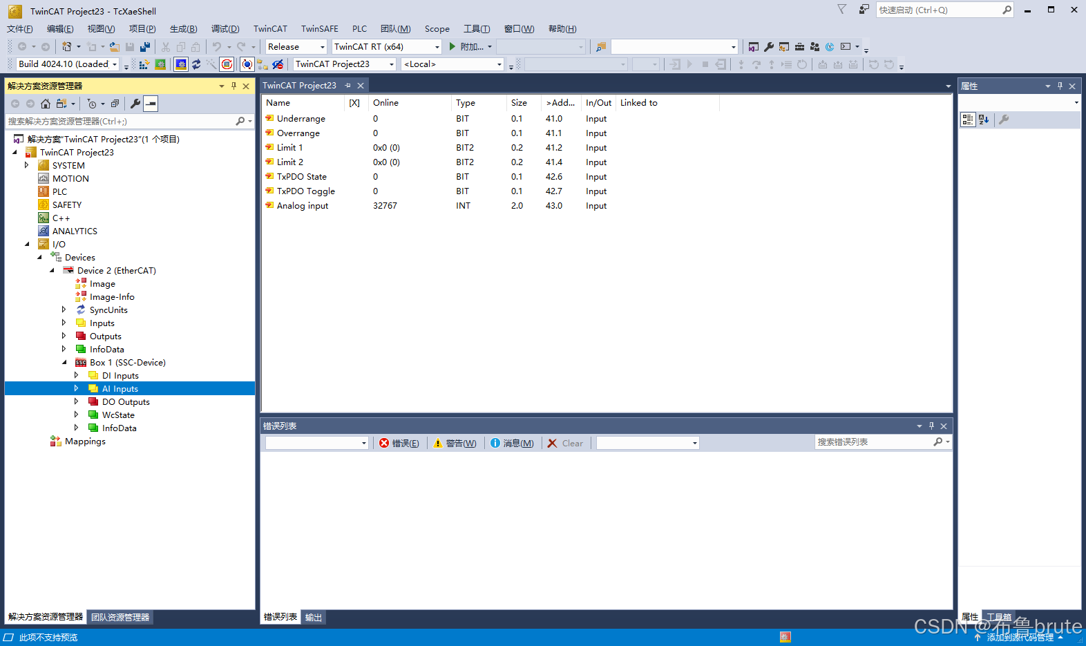
ok,连接完成
总结
最后回顾总结一下,STM32的基础用法,包括SPI,定时器,外部中断等,通过STM32CubeMX图形化生成HAL库开发环境再与AX58100进行配合。
以上基本上就是工程的全部,SSC相关自己去找一个改就可以了。
例程以及文章相关,有时间整理再上传。


 21万+
21万+

 被折叠的 条评论
为什么被折叠?
被折叠的 条评论
为什么被折叠?
 到【灌水乐园】发言


