


一. 实验目的:
深入了解STM32定时器原理,掌握脉宽调制pwm生成方法。
二. 实验内容:
1.定时器
(1).定时器类型分类比较:
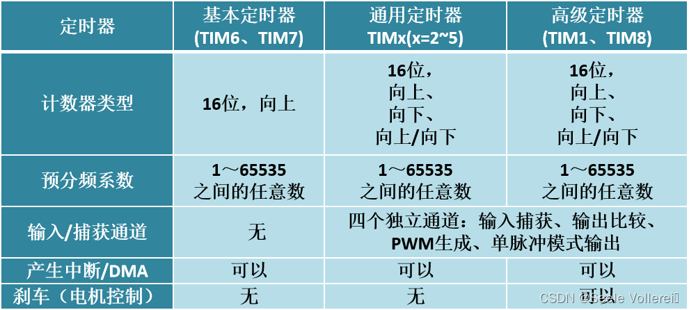
(2).通用定时器
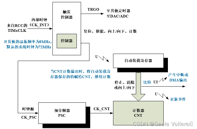
STM32通用定时器TIMx(x=2,3,4,5)主要由时钟源、时钟单元、捕获和比较通道等构成,核心是可编程预分频驱动的16位自动装载计数器。
(3).基本定时器
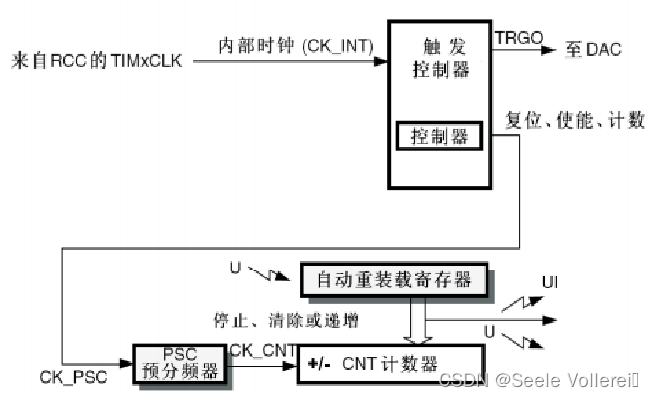
STM32有2个基本定时器TIM6和TIM7,可用作: 通用的16位计数器: 产生DAC触发信号 基本定时器的计数模式只有向上计数模式。
(4).高级定时器
TIM1和TIM8是STM32的2个16位的高级定时器*
2.LED闪烁实验
1. 使用STM32F103的 Tim2~Tim5其一定时器的某一个通道pin,连接一个LED,用定时器计数方式,控制LED以2s的频率周期性地亮-灭。
代码
MX_TIM3_Init();
/* USER CODE BEGIN 2 */
HAL_TIM_Base_Start_IT(&htim3);
//启动定时器TIM3定时中断
/* USER CODE END 2 */
/* USER CODE BEGIN 4 */
void HAL_TIM_PeriodElapsedCallback(TIM_HandleTypeDef *htim)
{
    if(htim->Instance == htim3.Instance)
  {
			HAL_GPIO_TogglePin(LED1_GPIO_Port,LED1_Pin);
	}
}
/* USER CODE END 4 */
效果:
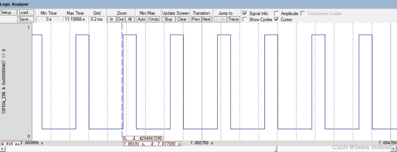
2. 接上,采用定时器PWM模式,让 LED 以呼吸灯方式渐亮渐灭,周期为1~2秒,自己调整占空比变化到一个满意效果;使用Keil虚拟示波器,观察 PWM输出波形。
代码
/* USER CODE BEGIN Header */
/**
  ******************************************************************************
  * @file           : main.c
  * @brief          : Main program body
  ******************************************************************************
  * @attention
  *
  * Copyright (c) 2024 STMicroelectronics.
  * All rights reserved.
  *
  * This software is licensed under terms that can be found in the LICENSE file
  * in the root directory of this software component.
  * If no LICENSE file comes with this software, it is provided AS-IS.
  *
  ******************************************************************************
  */
/* USER CODE END Header */
/* Includes ------------------------------------------------------------------*/
#include "main.h"
#include "tim.h"
#include "gpio.h"

/* Private includes ----------------------------------------------------------*/
/* USER CODE BEGIN Includes */

/* USER CODE END Includes */

/* Private typedef -----------------------------------------------------------*/
/* USER CODE BEGIN PTD */

/* USER CODE END PTD */

/* Private define ------------------------------------------------------------*/
/* USER CODE BEGIN PD */

/* USER CODE END PD */

/* Private macro -------------------------------------------------------------*/
/* USER CODE BEGIN PM */

/* USER CODE END PM */

/* Private variables ---------------------------------------------------------*/

/* USER CODE BEGIN PV */

/* USER CODE END PV */

/* Private function prototypes -----------------------------------------------*/
void SystemClock_Config(void);
/* USER CODE BEGIN PFP */

/* USER CODE END PFP */

/* Private user code ---------------------------------------------------------*/
/* USER CODE BEGIN 0 */

/* USER CODE END 0 */

/**
  * @brief  The application entry point.
  * @retval int
  */
int main(void)
{
	uint16_t pwmVal=0;
  /* USER CODE BEGIN 1 */

  /* USER CODE END 1 */

  /* MCU Configuration--------------------------------------------------------*/

  /* Reset of all peripherals, Initializes the Flash interface and the Systick. */
  HAL_Init();

  /* USER CODE BEGIN Init */

  /* USER CODE END Init */

  /* Configure the system clock */
  SystemClock_Config();

  /* USER CODE BEGIN SysInit */

  /* USER CODE END SysInit */

  /* Initialize all configured peripherals */
  MX_GPIO_Init();
  MX_TIM2_Init();
  MX_TIM3_Init();
  /* USER CODE BEGIN 2 */
  HAL_TIM_Base_Start_IT(&htim2);
  HAL_TIM_PWM_Start(&htim3,TIM_CHANNEL_1);

  /* USER CODE END 2 */

  /* Infinite loop */
  /* USER CODE BEGIN WHILE */
 while (1)
  {
    /* USER CODE END WHILE */

    /* USER CODE BEGIN 3 */
	  while (pwmVal< 500)
	  {
		  pwmVal++;
		  __HAL_TIM_SetCompare(&htim3, TIM_CHANNEL_1, pwmVal);    //?????,?????
//		  TIM3->CCR1 = pwmVal;    ?????
		  HAL_Delay(1);
	  }
	  while (pwmVal)
	  {
		  pwmVal--;
		  __HAL_TIM_SetCompare(&htim3, TIM_CHANNEL_1, pwmVal);    //?????,?????
//		  TIM3->CCR1 = pwmVal;     ?????
		  HAL_Delay(1);
	  }
	  HAL_Delay(200);

  }
  /* USER CODE END 3 */
}

/**
  * @brief System Clock Configuration
  * @retval None
  */
void SystemClock_Config(void)
{
  RCC_OscInitTypeDef RCC_OscInitStruct = {0};
  RCC_ClkInitTypeDef RCC_ClkInitStruct = {0};

  /** Initializes the RCC Oscillators according to the specified parameters
  * in the RCC_OscInitTypeDef structure.
  */
  RCC_OscInitStruct.OscillatorType = RCC_OSCILLATORTYPE_HSE;
  RCC_OscInitStruct.HSEState = RCC_HSE_ON;
  RCC_OscInitStruct.HSEPredivValue = RCC_HSE_PREDIV_DIV1;
  RCC_OscInitStruct.HSIState = RCC_HSI_ON;
  RCC_OscInitStruct.PLL.PLLState = RCC_PLL_ON;
  RCC_OscInitStruct.PLL.PLLSource = RCC_PLLSOURCE_HSE;
  RCC_OscInitStruct.PLL.PLLMUL = RCC_PLL_MUL9;
  if (HAL_RCC_OscConfig(&RCC_OscInitStruct) != HAL_OK)
  {
    Error_Handler();
  }

  /** Initializes the CPU, AHB and APB buses clocks
  */
  RCC_ClkInitStruct.ClockType = RCC_CLOCKTYPE_HCLK|RCC_CLOCKTYPE_SYSCLK
                              |RCC_CLOCKTYPE_PCLK1|RCC_CLOCKTYPE_PCLK2;
  RCC_ClkInitStruct.SYSCLKSource = RCC_SYSCLKSOURCE_PLLCLK;
  RCC_ClkInitStruct.AHBCLKDivider = RCC_SYSCLK_DIV1;
  RCC_ClkInitStruct.APB1CLKDivider = RCC_HCLK_DIV2;
  RCC_ClkInitStruct.APB2CLKDivider = RCC_HCLK_DIV1;

  if (HAL_RCC_ClockConfig(&RCC_ClkInitStruct, FLASH_LATENCY_2) != HAL_OK)
  {
    Error_Handler();
  }
}

/* USER CODE BEGIN 4 */
void HAL_TIM_PeriodElapsedCallback(TIM_HandleTypeDef *htim)
{
    static unsigned char ledState = 0;
    if (htim == (&htim2))
    {
        if (ledState == 0)
            HAL_GPIO_WritePin(GPIOA,GPIO_PIN_4,GPIO_PIN_RESET);
        else
            HAL_GPIO_WritePin(GPIOA,GPIO_PIN_4,GPIO_PIN_SET);
        ledState = !ledState;
    }
}

/* USER CODE END 4 */

/**
  * @brief  This function is executed in case of error occurrence.
  * @retval None
  */
void Error_Handler(void)
{
  /* USER CODE BEGIN Error_Handler_Debug */
  /* User can add his own implementation to report the HAL error return state */
  __disable_irq();
  while (1)
  {
  }
  /* USER CODE END Error_Handler_Debug */
}

#ifdef  USE_FULL_ASSERT
/**
  * @brief  Reports the name of the source file and the source line number
  *         where the assert_param error has occurred.
  * @param  file: pointer to the source file name
  * @param  line: assert_param error line source number
  * @retval None
  */
void assert_failed(uint8_t *file, uint32_t line)
{
  /* USER CODE BEGIN 6 */
  /* User can add his own implementation to report the file name and line number,
     ex: printf("Wrong parameters value: file %s on line %d\r\n", file, line) */
  /* USER CODE END 6 */
}
#endif /* USE_FULL_ASSERT */
效果:
3.仿真波形图:
三、总结
本次实验通过对led的闪烁和呼吸灯来了解定时器的运用,从而实现对定时器的初步了解,如有错误还望指正。


 1477
1477

 被折叠的 条评论
为什么被折叠?
被折叠的 条评论
为什么被折叠?
 到【灌水乐园】发言


