


我说,你是人间的四月天。——林徽因,1934年《你是人间的四月天》。
I said, Thou art the April day of the earth. – Lin Huiyin, 1934 “You are the April Day of the World”.
目录
2.1 From linear to nonlinear, discrete to continuous: what reality looks like
2.2 From micro to macro: amplification in circuits
2.3 From Theory to Theory: System of Systems
0. Abstract:
This paper is a primer on the basic content of analogue electronics in relation to science and technology, with a simple textual description supported by concise mathematical formulas, analytical illustrations and an overall introduction. Also, several points are presented.
Keywords: fundamentals of analogue electronics; primer; NI Multisim 14.0; MATLAB R2023b
Citation format:HI Engie. a Description of the Fundamentals of Analog Electronics[EB/OL]. (2024-05-07)[xxxx-xx-xx]. http://z6b.cn/sdlIc.
1. Introduction
Here, as much as possible, a generalisation or introduction to rigorous and often convoluted science and technology is made, using words and rhetorical methods that approximate the classical yet are expected to work and dissect the unfolding. This is also the first point of the paper.
2. Body
2.1 From linear to nonlinear, discrete to continuous: what reality looks like
In traditional RLC circuits, as well as in power supplies and switches, it is all linear, one or the other (obviously, in this case, conductive); in reality, this is not enough to be used and close, so non-linear, continuous properties are put into ‘semiconductors’, which can be imagined to give rise to more flexible applications. At the same time, our line of research is electronic devices/equipment, circuits/systems. How can semiconductors be realised? As the only electrons were in motion before, we thought that it would be fundamental to add another medium, i.e., ‘doping’. So, outside of Ge, Si, etc., we ‘brake with motion’, as ‘heaven and earth intersect and all things are connected’, ‘poor is change, change is pass’. Unlike the previous only electrons, we assumed a positively charged ‘hole’ as the second medium or carriers, so that the internal material has formed the movement of the field and the current, you can imagine that in the internal structural changes and the external additional current there will be more combinations and changes, which is close to the actual and our needs. This structure is the ‘PN junction’, and the ‘diode’ is formed when we draw two polarised terminals at its ends. Here we should reiterate an important point: in scientific applications and engineering problems, when the physical nature is clear, the rest is mathematical. Therefore, the second point we advocate is the greater use of mathematics or advanced mathematics. Returning to the title of the text, what then can a triode do? We imagine electronic circuits to be a series of operations (note: operational circuits are much the same), and input and output are naturally what we care about, and the diode is a versatile equation. Here to raise a third point: in the general education and teaching tend to introduce a bunch of concepts, we should consider this necessary but not sufficient; or, based on the two previous points, we can point out the third point can be a little (this paper with double quotes to mark this). Returning to the title of the paper, the equation for the PN junction is as follows:
The fourth point is made here: all changes will have a tendency to increase. For example, since a PN junction to form a diode, then two PN junctions can naturally form a ‘triode’; at this point in the mathematics, that is, from a unitary function to a binary function, that is:
At the same time, according to the combination of the PN junction is divided into two kinds of PNP and NPN, and this is from bipolar to unipolar. So is there a tetrode? It is unknown at this time. Later, field effect tubes using only one type of carrier appeared, first as J-FETs, and then as ‘MOS-FETs,’ a combination of metal, oxide, and semiconductor, which made the situation even more complicated.
2.2 From Micro to Macro: Amplification in Circuits
What is the use for the devices of 2.1? On the one hand, we understand their respective principles, structures, and performance specifications; on the other hand, we are about to use them. Diodes can be used to limit, to form logical switches, and so on. The triode is the protagonist of this article, in which we achieve amplification, a concept that should be recognised from the microelectronics from the lead, that is, full of great significance. In an ordinary triode, the ‘collector’ current is an amplification of the ‘base electrode’ current, which is regarded as a valve. On this basis, there are three basic amplification circuits, but also the emergence of ‘integrated operational amplifier circuits’, which is a very effective electronic programme.
2.3 From Theory to Theory: System of Systems
The foregoing is basically an observation of electronic circuits, but for the systems they form, as in the perspective of the second point, there are more modes of systems (note: modern mathematics is also considered to be a mode of study, and systems science took off in the twentieth century). In the foregoing, current and voltage are the basic physical quantities, resistance, etc., is more of a coefficient or a result of characterisation, and power is a commonly used physical quantity; due to the increased use of alternating current (AC), ‘frequency response’ is the basic method of analysing signals, resulting in an ‘electronic information system’ (EIS). This results in an ‘electronic information system’, which in information electronics is often modelled on small signals, while the corresponding power electronics is the other way round for high power. In this system, we have carried out on the signal: extraction, processing, conversion, implementation, and processing with A/D conversion through the computer and other electronic equipment, and then through the D / A conversion to the implementation of the part; this is the conventional design ideas.
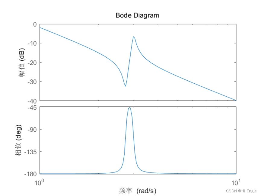
Fig.1 A Example of Bode Graph
On the other hand, the changes in this system are close to reality, easy to analyse, and the development of science and technology, we want to be more intelligent, then we can introduce ‘feedback’ as a ‘closed-loop control system’. That is, there is:
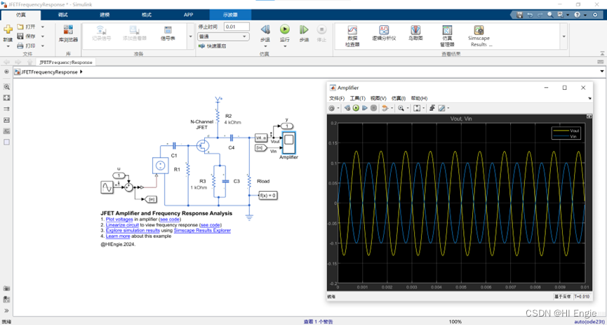
Fig.2 The MathWorks, Inc. MATLAB/Simulink/Simscape Electrical/JFET Amplifier and Frequency Response Analysis.
2.4 Additions
The reason is to add, because the line to the main clues to spread, which is the biggest point of this paper, then have to put some of the content here. The aforementioned completed the core of electronic circuit design, then the circuit as a ‘power grid’ (which is also like the information theory point of view), we also need to analyse the inputs, that is, the power supply, here we introduce the ‘DC regulated power supply’. The reason for this name is that the output of electricity from the power station to the consumer is generally AC, variable voltage. The classic method for this is:
Variable voltage, using a transformer to first reduce the voltage from 220V50Hz (China's current standard), that is, the amplitude of the waveform is reduced;
Rectification, using a bridge circuit with one diode or four diodes to show the waveform as a positive semiaxial portion, which will flip a portion vertically to the positive side if full wave rectification is used;
Filtering, using C, LC, CRC circuits, etc., e.g. to flatten the ripples of a sine wave;
Voltage regulation: this is done using the regulator diode circuit role in section 2.1 (this is generally used for small currents), etc., to turn the ripple into a straight line.
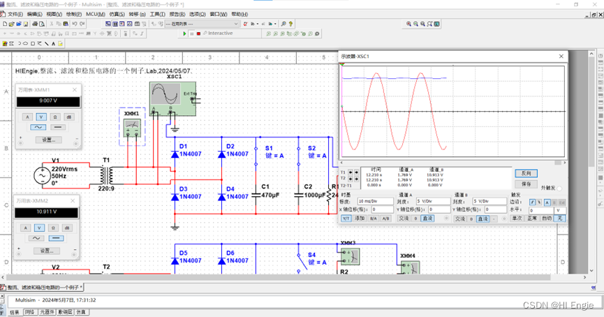
Fig.3 An example of a single-phase rectifier bridge filter circuit
3. Summary
The first version of this paper, ‘A description of analog electronic technology’, was published on 2024/04/22. This paper is suitable for use as a tutorial for electrical, automation, electronic and some non-electrical aspects related to analog electronic technology, or as a guide for engineers and technicians. It also serves as a guide for engineers and technicians. At the same time, it strives for the second goal: to be concise, with a view to serving as a quick practical guide.
4. Acknowledgements
Acknowledgement time: 3:18.45. Second acknowledgement time: 3:22:09.211.
5. References (and links)
[1]Wang, Xiaolan. Fundamentals of analogue electronics [M]. Beijing: Mechanical Industry Press, 2016.
[2]Donald A. Neamen. electronic circuits: analysis and design [M]. 3rd edition. Chennai: McGraw-Hill Compress, 2007.
[3]NONO.97.[Knowledge summary] Analogue electronics (analogue electricity) [EB/OL]. (2022-08-29). https://blog.csdn.net/weixin_51130221/article/details/126538175.html.
[4]Information on the wallpaper at the beginning of the article → https://www.4kbizhi.com/wallpaper/9776.
[5]Information about the wallpaper at the end of the article → http://www.netbian.com/desk/31656.
[6]Information on inserting mathematical formulas in CSDN → https://blog.csdn.net/weixin_44244154/article/details/104722239.
[7]Norms for capitalisation of English essay titles → https://blog.wordvice.cn/title-capitalization-rules-for-research-papers.
[8]https://www.bilibili.com/video/BV1Vp4y1y7wR/?spm_id_from=333.337.search-card.all.click&vd_source= fe02950014ff487074ae95655dda4a78.
This article is also published on the following platforms: Baidu Bai Jiahao, bilibili, Tik Tok, Jin RItoutiao, WeChat Gong Zhonghao, Weibo, Zhihu, and China's professional IT community(CSDN).

How did you feel about this article? Did it help you? Looking forward to your scoring. Feel free to discuss any ideas in the comments section or private message or email, etc. Have a nice life!


 1万+
1万+


 被折叠的 条评论
为什么被折叠?
被折叠的 条评论
为什么被折叠?
 到【灌水乐园】发言


