


目录
产品概述
DHT11 数字温湿度传感器是一款含有已校准数字信号输出的温湿度复合传感器。它应用专用的数 字模块采集技术和温湿度传感技术,确保产品具有极高的可靠性与卓越的长期稳定性。传感器包括一 个电容式感湿元件和一个 NTC 测温元件,并与一个高性能 8 位单片机相连接。
模块接线
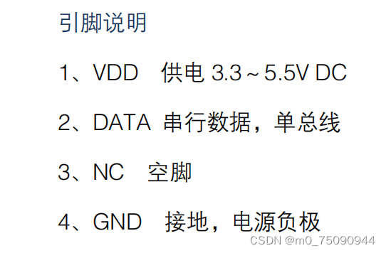
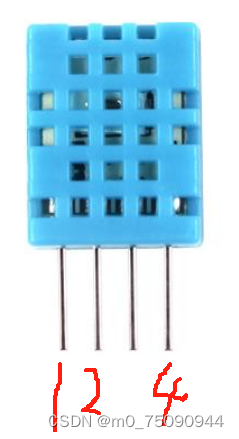
1.典型应用电路中建议连接线长度短于5m时用4.7K上拉电阻,大于5m时根据实际情况降低上拉电阻的阻值。
2. 使用3.3V电压供电时连接线尽量短,接线过长会导致传感器供电不足,造成测量偏差。
3. 每次读出的温湿度数值是上一次测量的结果,欲获取实时数据,需连续读取2次,但不建议连续多次读取传感器,每次读取传感器间隔大于2秒即可获得准确的数据。
4. 电源部分如有波动,会影响到温度。如使用开关电源纹波过大,温度会出现跳动。
测量范围
相对湿度:5%~95%RH
温度:-20~60℃
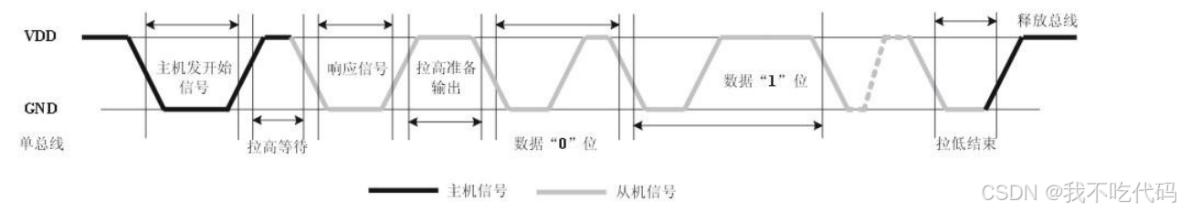
数据时序图
用户主机(MCU)发送一次开始信号后,DHT11 从低功耗模式转换到高速模式,待主机开始信号结束 后,DHT11 发送响应信号,送出 40bit 的数据,并触发一次信采集。信号发送如图所示。
数据时序图
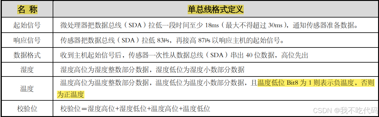
DHT11单总线定义
单总线读取步骤
主机和从机之间的通信可通过如下几个步骤完成外设(如微处理器)读取 DHT11 的数据的步骤)。
步骤一
DHT11 上电后(DHT11 上电后要等待 1S 以越过不稳定状态在此期间不能发送任何指令),测试环境 温湿度数据,并记录数据,同时 DHT11 的 DATA 数据线由上拉电阻拉高一直保持高电平;此时 DHT11 的 DATA 引脚处于输入状态,时刻检测外部信号。
 最低0.47元/天 解锁文章


 4829
4829

 被折叠的 条评论
为什么被折叠?
被折叠的 条评论
为什么被折叠?
 到【灌水乐园】发言


