


Description
Under certain conditions, during power-on and power-off the integrity of the Zynq-7000 AP SoC PS eFUSE settings can be affected.
If ALL of the following occur, then the integrity of the Zynq-7000 AP SoC PS eFUSE settings can be affected:
- The recommended power-on and power-off sequences are not met
- PS_CLK is running during power-on and/or power-off
- PS_POR_B is not asserted as required during PS power-on or PS_POR_B is not asserted during power-off
Symptoms can include the following:
- Failure to boot due to unintended enable of RSA authentication or incorrect RSA PPK hash value
- Longer than expected boot times due to unintended enable of OCM ROM 128KB CRC check
- Error during PS eFUSE programming due to unintended write-protect setting or blank check error
Solution
Zynq-7000 AP SoC designs should be evaluated for potential impact to PS eFUSE integrity.
See the sections below for methods to evaluate potential impact.
How do I evaluate if my design is impacted during power-on?
If the answers to ALL three of the following power-on test questions are NO, then the PS eFUSE integrity might be impacted during power-on.
See the "When further analysis is needed" section below.
- Power-on test 1: Does PS_POR_B meet the datasheet requirements for power-on and is asserted low (GND) until VCCPINT, VCCPAUX , and VCCO_MIO0 have reached their minimum voltage levels? If YES, then NO RISK. Passing this test is represented in solution 1.
- Power-on test 2: Is the PS reference clock (PS_CLK) inactive until VCCPINT has reached 0.80V? If YES, then NO RISK. Passing this test is represented in solution 2.
- Power-on test 3: Does the power supply sequence follow the recommended power-on sequence (1: VCCPINT, 2: VCCPAUX, 3: VCCO_MIO0)?
VCCPINT must reach 0.80V before both VCCPAUX reaches 0.70V and VCCO_MIO0 reaches 0.90V.
If YES, then NO RISK. Passing this test is represented in solution 3.

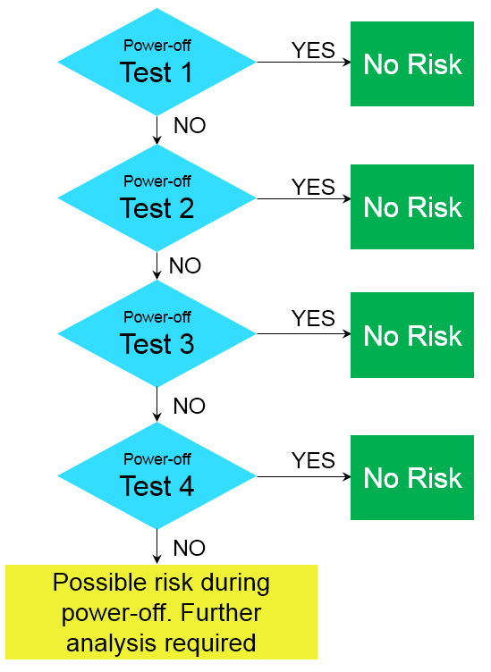
How do I evaluate if my design is impacted during power-off?
If the answers to ALL four of the preceding power-off tests are NO, then the PS eFUSE integrity might be impacted during power-off.
See the "When further analysis is needed" section below.
- Power-off test 1: Is PS_POR_B asserted (GND) before VCCPINT reaches 0.80V and held asserted until VCCPINT is lower than 0.40V or VCCPAUX is lower than 0.70V or VCCO_MIO0 is lower than 0.90V?
If YES, then NO RISK. Passing this test is represented in solution 4. - Power-off test 2: Is the PS reference clock (PS_CLK) inactive before VCCPINT has reached 0.80V?
If YES, then NO RISK. Passing this test is represented in solution 5. - Power-off test 3: Does the power supply sequence follow the recommended power-off sequence (1: VCCO_MIO0, 2: VCCPAUX, 3: VCCPINT)? That is, does VCCO_MIO0 reach 0.90V or VCCPAUX reach 0.70V before VCCPINT reaches 0.80V?
If YES, then NO RISK. Passing this test is represented in solution 6. - Power-off test 4: Is PS_POR_B held de-asserted (VCCO_MIO0) and the voltage ramp downs on VCCPINT, VCCPAUXand VCCO_MIO0 are monotonic until at least one of the supplies reaches and stays below 0.40V, 0.70V and 0.90V respectively?
If YES, then NO RISK. Passing this test is represented in solution 7.
For systems exhibiting the symptoms, how do I check the integrity of my PS eFUSE?
See the Attachments section below for an XMD script that can read the PS eFUSE array for determining whether any PS eFUSE settings are different to the expected settings.
Follow the instructions in the ReadMe.txt file in the attachment.
When further analysis is needed for existing board designs
For further analysis of an existing board design, open a Xilinx Support Service Request and prepare to share the following:
-
Symptoms, if any, of the issue.
-
If symptoms are observed, then you will need the PS eFUSE array condition (ps_efuse.log file).
Get this by running the attached zynq_efuse_read_normal.zip utility. See the Attachments section. -
4-channel scope shots of PS_POR_B, V CCPINT, V CCPAUX, V CCO_MIO0
-
Zoom into power-on sequence
-
Zoom into power-off sequence
-
-
Scope shot of PS_CLK activity relative to one or more of the above channels for power-on and power-off
Available Solutions for Ensuring PS eFUSE Integrity
Multiple solutions are available to ensure PS eFUSE integrity. At least one solution for power-on and at least one solution for power-off must be satisfied to ensure PS eFUSE integrity.
These solutions are classified into the following categories:
- Controlling PS_POR_B during power-on (solution 1) and power-off (solution 4) ramping phases
- Controlling PS_CLK during power-on (solution 2) and power-off (solution 5) ramping phases
- Controlling power-on (solution 3) and power-off (solution 6) sequences
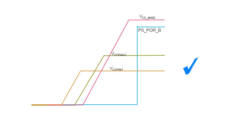
Solution 1 for Power-On:
Meet the data sheet requirement for PS_POR_B.
The PS_POR_B is required to be asserted until the VCCPINT, VCCPAUX and VCCO_MIO0 have reached minimum operating levels.
In addition, review the PS reset assertion timing requirements in the data sheet for concerns regarding (Xilinx Answer 63149)
Solution 2 for Power-On:
Disable PS reference clock (PS_CLK) until VCCPINT > 0.80V.

Solution 3 for Power-On:
Follow the recommended PS power-on sequence in the data sheet.
Specifically, to ensure PS eFUSE integrity, VCCPINT must reach 0.80V before both VCCPAUX reaches 0.70V and VCCO_MIO0 reaches 0.90V.

Solution 4 for Power-Off:
Assert PS_POR_B to GND before VCCPINT reaches 0.80V and hold asserted until VCCPINT is lower than 0.40V, VCCPAUX is lower than 0.70V, or VCCO_MIO0 is lower than 0.90V.

Solution 5 for Power-Off:
Disable the PS reference clock (PS_CLK) before VCCPINT < 0.80V.

Solution 6 for Power-Off:
Follow the recommended PS power-off sequence in the data sheet.
Specifically, to ensure PS eFUSE integrity, VCCO_MIO0 must reach 0.90V or VCCPAUX must reach 0.70V before VCCPINTreaches 0.80V

Solution 7 for Power-Off:
PS_POR_B held de-asserted (VCCO_MIO0) and the voltage ramp downs on VCCPINT, VCCPAUX and VCCO_MIO0 aremonotonic until at least one of the supplies reaches and stays below 0.40V, 0.70V and 0.90V respectively

PVT CONSIDERATION:
The above conditions for power on and power off must be satisfied for any variations in process, voltage and temperature.
The limits on VCCPINT, VCCPAUX and VCCMIO have been characterized considering different PVT conditions.
However, the user needs to confirm any variations on PS_CLK or PS_POR_B will not trigger a failing condition under different PVT scenarios.
Attachments
Associated Attachments
| Name | File Size | File Type |
|---|---|---|
| zynq_efuse_read_normal.zip | 832 KB | ZIP |
| AR65240_-_Example_PS_POR_B_Supervisor_Circuit.pdf | 187 KB |
https://www.xilinx.com/support/answers/63149.html
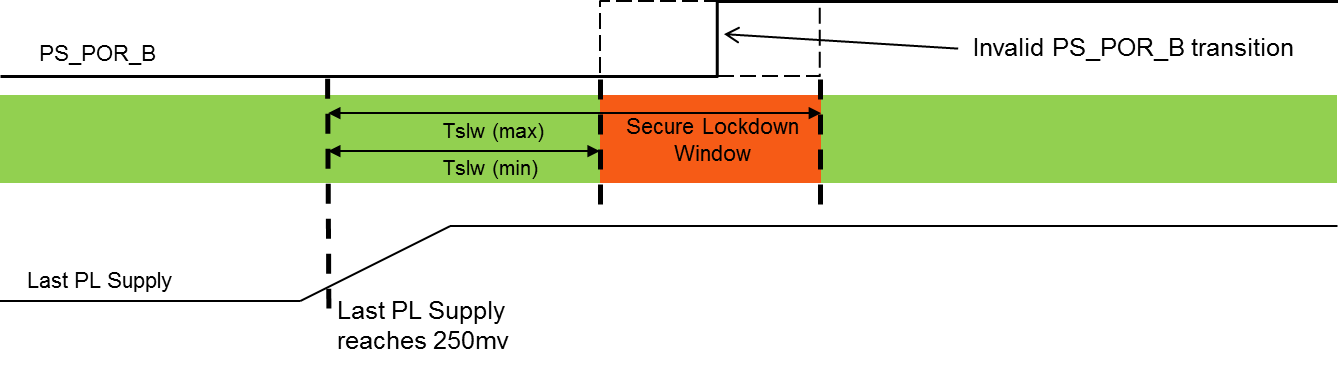
Description
This window is defined as a minimum and maximum time relative to the last PL power supply ramp:
Tslw (min) = Time from last PL power supply reaching 250mv to start of Secure Lockdown Window
Tslw (max) = Time from last PL power supply reaching 250mv to end of Secure Lockdown Window
Solution
- Identify probe points for PS_POR_B, VCCINT (PL), VCCAUX (PL), VCCBRAM, VCCO_0 (PL).
- For PL supply, identify the probe points near to the die, typically on the supply bypass capacitor.
- Use an oscilloscope to measure the relative time between the signals for Test 1 and Test 2.
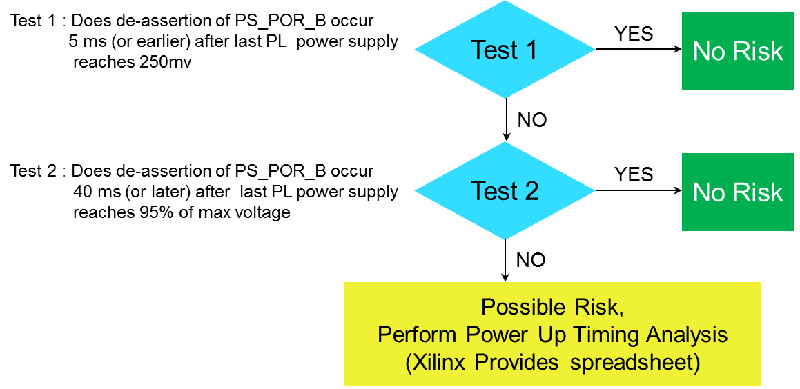
In the "Possible Risk" scenario, the power up sequence and de-assertion timing of PS_POR_B must be analyzed to determine if it falls within the Secure Lockdown timing window (Tslw).
If PS_POR_B is de-asserted either before or after this window, the device is not exposed this behavior.
- Change timing relationship between last PL power ramp and PS_POR_B using PCB level circuits (Preferred Solution)
- Change PS BootROM code execution time (*) to shift the window by
- enabling 128K CRC check by burning a PS eFuse bit
- enabling PLL Bypass (**)
IMPORTANT: Contact your local Xilinx FAE or open a support webcase for further assistance.
Please, open a webcase with "Secure Lockdown Window" in the title ONLY after collecting the following:
- Results of the attached spreadsheet analysis (a snapshot of the timing in the spreadsheet)
- Scope-shots of PS_POR_B, VCCINT (PL), VCCAUX (PL), VCCBRAM, VCCO_0 (PL) and INIT_B (the time relationship between the signals is required)


 1657
1657

 被折叠的 条评论
为什么被折叠?
被折叠的 条评论
为什么被折叠?
 到【灌水乐园】发言


