1 几个条件
干涉测量的条件,或者说干涉测量的要求,主要从以下几个方面进行考虑:
* 物理过程对应的形变的大小;
* 像素大小、幅宽、以及系统性能能;
* 时间间隔(时间主要会导致去相关,似乎正是这个限制导出了形变大小、像素大小、坡度角等限制);
* 坡度角(斜坡效应);
* 基线限制(跟轨道数据的限制和平台的限制也是有联系的)
* limitations in distinguishing between the different geophysical or induced sources of coherent phase variation (由于干涉相位中包含了有很多因素,某一种应用的成功取决于先验条件的精确性,比如说用于辅助形变测量的DEM的精度);
* Other limiting conditions can occur in the interferometric processing sequence(eg. phase unwarping);
跟相位解缠相近的:The second type of ambiguity arises because interferograms record relative changes in phase, not absolute changes. In other words, we cannot identify the fringe corresponding to zero change in phase, i.e., the contour of null deformation. Mathematically, we are free to add a constant value (or “offset”) to all the pixels in an interferogram. This ambiguity persists even if the interferogram has been unwrapped. Usually, we can determine this constant by assumption (e.g., null deformation at one point) or independent measurement (e.g., a GPS survey).
* Others depending on the application of the products.
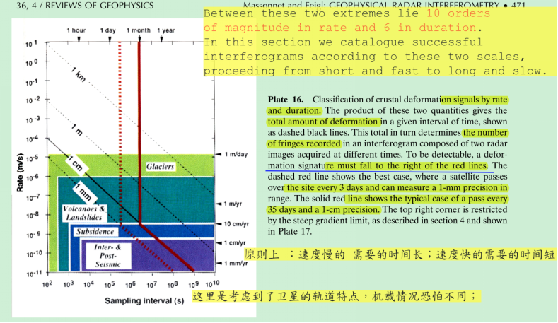
2 利用图形表示这些conditions
3 conditions 之间的联系
这些限制大多都是相通的,毕竟其本质上是对相干性的限制。一个很好的切入角度是:
干涉测量的关键在于相减的两个相位的随机性能够被抵消。
For this, the elementary targets must remain stable. This condition is met if the two images are taken at the same time. A more geometric condition requires that elementary targets within a pixel contribute the same way to both images. Therefore the pixel must not stretch or shrink by more than a fraction of the wavelength from one image to the other. Otherwise, targets at both ends of a given pixel will add differently in each image, leading to internal phase contributions that do not cancel by subtraction. Mathematically, let
L
represent the length perpendicular to the trajectory of a pixel on the ground (20 m for ERS-1), let
restricts the separation between the satellite’s orbital trajectories during the two image acquisitions to typically less than 1 km (for ERS-1).
Fortunately, satellite orbits are designed to repeat identically after a period of time called the orbital cycle and generally meet this condition.
The local slope of the terrain influences this condition. Close to the interferometric limit (1), even a moderate slope with the wrong orientation will blur fringes. According to (1), steep incidence, coarse resolution, and short wavelength all make the condition harder to satisfy.
这个基本的公式由相干性导出,包含的限制有:基线、坡度角、像素大小、波长以及形变。相干性是根本要求,坡度角、轨道数据精度、形变大小等只是他的一个侧面。
Similarly, the direction of observation must also be identical for the two images; otherwise, elementary targets will sum differently in the along-track direction of the pixel. The interferogram degrades linearly with the angle between the two directions of observation. The degradation becomes total when this angle exceeds the width of the antenna beam (typically 0.3 for ERS-1). In signal-processing terms, this happens as soon as the illuminated areas (Figure 1) cease to overlap in the along-track direction, creating an excessively large difference between the “mean Doppler” of the two images. (这个与方位向频谱偏移是否是一回儿事?)
这个式子还可以看出形变测量的限制:
The necessary condition for interferometry (relation (1)) implies that the maximum detectable deformation gradient is one fringe per pixel, or the dimensionless ratio of the pixel size to the wavelength. This value depends on the satellite; it is 3×10⁻³ for ERS and 13×10−3 for JERS. For instance, the coseismic deformation in the Landers earthquake locally exceeded this threshold, creating incoherence.
Similarly, block rotation can change the radar observation direction sufficiently to violate the necessary condition for interferometry. Such a change of direction of observation produces a set of parallel fringes oriented perpendicular to the satellite track. As for the gradient limit, where we cannot exceed one fringe of range change per range pixel, we cannot accept more than one fringe per azimuth pixel. Areas close to this limit appear in the vicinity of the Landers fault. The limit is found when a round trip range change of one wavelength is created across the azimuth pixel size. (这个与方位向频谱偏移是否是一回儿事?)
4 说明
The user may also spoil the interferometric effect by applying slightly different processing procedures to each image. Such a slight mistake can damage the interferogram more than a huge error consistently applied to both images in the pair.
Abrupt changes in topography, such as volcanic eruptions, can exceed this limit(the gradient of the surface deformation). Discontinuities such as surface rupture also exceed this limit because they produce an infinite gradient. In this case, however, we can still measure the relative motion on opposite sides of a fault by counting fringes along a path which runs around the end of the fault [Massonnet et al., 1993b, Figure 3b].
这些限制条件并不绝对
Even if the range gradient caused by deformation on the ground exceeds the limit of one fringe per pixel, a judicious choice of image pairs may yield a usable interferogram. For example, a large orbital separation can create a fringe gradient that just compensates that of the ground deformation, bringing the geometric configuration back within the interferometric limits. Similarly, a difference in the mean Doppler between two images could compensate for rotation on the ground. In this way it should be possible to calculate useful fringes in parts of a high gradient deformation field using an otherwise unusable image pair. However, the topographic sensitivity associated with a larger orbital separation would prevent the use of this technique in hilly terrain because it would require removing topographic effects with a proportionally accurate DEM.
5 参考文献
Hooper, A., Bekaert, D., Spaans, K., & Arıkan, M. (2012). Recent advances in SAR interferometry time series analysis for measuring crustal deformation. Tectonophysics, 514, 1-13.
Zhong, L., & Dzurisin, D. (2014). Insar imaging of aleutian volcanoes. Springer Praxis Books, 2014(8), 1778–1786.
Ketelaar, V. (2009). Satellite radar interferometry : subsidence monitoring techniques.
RADAR INTERFEROMETRY Data Interpretation and Error Analysis.pdf


 3807
3807

 被折叠的 条评论
为什么被折叠?


