


前言
本篇博客主要介绍基本定时器中的源码解析,会涉及以下两个部分:
- 以整点原子定时器中断实验的程序为蓝本的程序解析
- 重点的结构体介绍
需要注意的是:本文介绍的源代码由正点原子提供,可能会根据个人习惯进行适量调整,与增加注释。该程序使用的并非高级定时器TIM1或者TIM8,而是通用定时器TIM3。但是,他们程序上是兼容的。在自我实现的代码中,严格使用高级寄存器。相关内容将会在下篇文章详细介绍。
由于基本定时器不会与外界有直接的硬件连接,本文就不介绍硬件情况。
HAL库版本:
- STM32Cube_FW_F4_V1.25.0
本文主要参考文章为:
- RM0090 参考手册
自己写的代码的详细分析可以参考博客<STM32CubeMX第五篇之PWM>。
结构体
TIM_OC_InitTypeDef
/**
  * @brief  TIM Output Compare Configuration Structure definition
  */
typedef struct
{
  uint32_t OCMode;        /*!< Specifies the TIM mode.
                               This parameter can be a value of @ref TIM_Output_Compare_and_PWM_modes */

  uint32_t Pulse;         /*!< Specifies the pulse value to be loaded into the Capture Compare Register.
                               This parameter can be a number between Min_Data = 0x0000 and Max_Data = 0xFFFF */

  uint32_t OCPolarity;    /*!< Specifies the output polarity.
                               This parameter can be a value of @ref TIM_Output_Compare_Polarity */

  uint32_t OCNPolarity;   /*!< Specifies the complementary output polarity.
                               This parameter can be a value of @ref TIM_Output_Compare_N_Polarity
                               @note This parameter is valid only for timer instances supporting break feature. */

  uint32_t OCFastMode;    /*!< Specifies the Fast mode state.
                               This parameter can be a value of @ref TIM_Output_Fast_State
                               @note This parameter is valid only in PWM1 and PWM2 mode. */


  uint32_t OCIdleState;   /*!< Specifies the TIM Output Compare pin state during Idle state.
                               This parameter can be a value of @ref TIM_Output_Compare_Idle_State
                               @note This parameter is valid only for timer instances supporting break feature. */

  uint32_t OCNIdleState;  /*!< Specifies the TIM Output Compare pin state during Idle state.
                               This parameter can be a value of @ref TIM_Output_Compare_N_Idle_State
                               @note This parameter is valid only for timer instances supporting break feature. */
} TIM_OC_InitTypeDef;
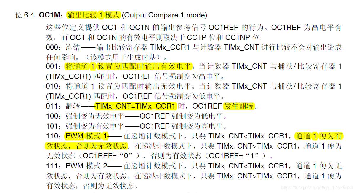
OCMode(输出通道模式)
/** @defgroup TIM_Output_Compare_and_PWM_modes TIM Output Compare and PWM Modes
  * @{
  */
#define TIM_OCMODE_TIMING                   0x00000000U                                              /*!< Frozen                                 */
#define TIM_OCMODE_ACTIVE                   TIM_CCMR1_OC1M_0                                         /*!< Set channel to active level on match   */
#define TIM_OCMODE_INACTIVE                 TIM_CCMR1_OC1M_1                                         /*!< Set channel to inactive level on match */
#define TIM_OCMODE_TOGGLE                   (TIM_CCMR1_OC1M_1 | TIM_CCMR1_OC1M_0)                    /*!< Toggle                                 */
#define TIM_OCMODE_PWM1                     (TIM_CCMR1_OC1M_2 | TIM_CCMR1_OC1M_1)                    /*!< PWM mode 1                             */
#define TIM_OCMODE_PWM2                     (TIM_CCMR1_OC1M_2 | TIM_CCMR1_OC1M_1 | TIM_CCMR1_OC1M_0) /*!< PWM mode 2                             */
#define TIM_OCMODE_FORCED_ACTIVE            (TIM_CCMR1_OC1M_2 | TIM_CCMR1_OC1M_0)                    /*!< Force active level                     */
#define TIM_OCMODE_FORCED_INACTIVE          TIM_CCMR1_OC1M_2                                         /*!< Force inactive level                   */
/**
  * @}
  */
该部分对应寄存器TIMx_CCMR1的OC1M位。
Pulse(脉冲值)
该脉冲值即为比较值,通过比较计数器中的计数值与该值的大小关系,来转变输出电平的高低。
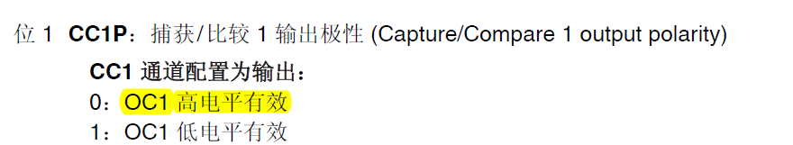
OCPolarity(输出极性)
该参数的取值范围如下:
/** @defgroup TIM_Output_Compare_Polarity TIM Output Compare Polarity
  * @{
  */
#define TIM_OCPOLARITY_HIGH                0x00000000U                          /*!< Capture/Compare output polarity  */
#define TIM_OCPOLARITY_LOW                 TIM_CCER_CC1P                        /*!< Capture/Compare output polarity  */
/**
  * @}
  */
该参数用于确定有效电平的极性,对应手册为:
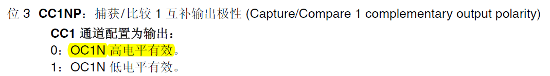
OCNPolarity(互补输出通道极性)
该参数的取值范围如下:
/** @defgroup TIM_Output_Compare_N_Polarity TIM Complementary Output Compare Polarity
  * @{
  */
#define TIM_OCNPOLARITY_HIGH               0x00000000U                          /*!< Capture/Compare complementary output polarity */
#define TIM_OCNPOLARITY_LOW                TIM_CCER_CC1NP                       /*!< Capture/Compare complementary output polarity */
/**
  * @}
  */
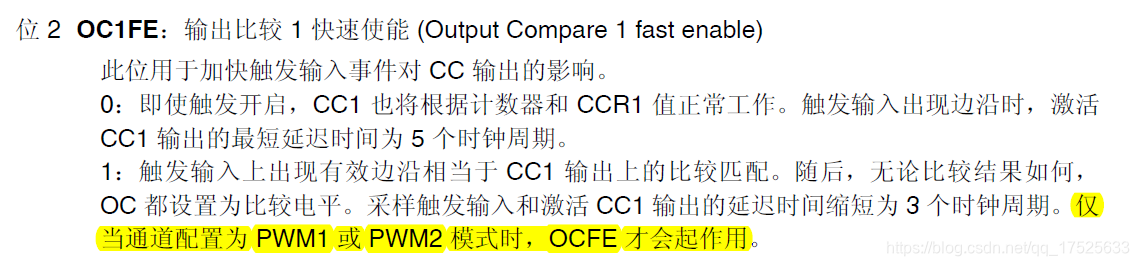
OCFastMode(输出通道快速模式)
/** @defgroup TIM_Output_Fast_State TIM Output Fast State
  * @{
  */
#define TIM_OCFAST_DISABLE                 0x00000000U                          /*!< Output Compare fast disable */
#define TIM_OCFAST_ENABLE                  TIM_CCMR1_OC1FE                      /*!< Output Compare fast enable  */
/**
  * @}
  */
OCIdleState(输出通道闲置状态)
/** @defgroup TIM_Output_Compare_Idle_State TIM Output Compare Idle State
  * @{
  */
#define TIM_OCIDLESTATE_SET                TIM_CR2_OIS1                         /*!< Output Idle state: OCx=1 when MOE=0 */
#define TIM_OCIDLESTATE_RESET              0x00000000U                          /*!< Output Idle state: OCx=0 when MOE=0 */
/**
  * @}
  */
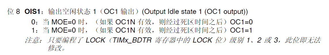
注意:
所谓的闲置状态就是MOE=0时候的状态,需要注意的是,当刹车功能起作用时,即将MOE设置为0,进入闲置状态。
OCNIdleState(互补输出通道闲置状态)
/** @defgroup TIM_Output_Compare_N_Idle_State TIM Complementary Output Compare Idle State
  * @{
  */
#define TIM_OCNIDLESTATE_SET               TIM_CR2_OIS1N                        /*!< Complementary output Idle state: OCxN=1 when MOE=0 */
#define TIM_OCNIDLESTATE_RESET             0x00000000U                          /*!< Complementary output Idle state: OCxN=0 when MOE=0 */
/**
  * @}
  */

源代码
整个源代码的体系如下:
主函数
#include "sys.h"
#include "delay.h"
#include "usart.h"
#include "led.h"
#include "timer.h"

int main(void)
{
    u8 dir = 1;                      //PWM调整方向标志
    u16 led0pwmval = 0;              //占空比参数
    HAL_Init();                      //HAL库初始化
    Stm32_Clock_Init(360, 25, 2, 8); //时钟初始化
    delay_init(180);                 //延时函数初始化
    uart_init(115200);               //串口初始化
    LED_Init();                      //LED初始化

    TIM3_PWM_Init(500 - 1, 90 - 1);  //PWM初始化:90M/90=1M的计数频率,自动重装载为500,那么PWM频率为1M/500=2kHZ

    while (1)
    {
        delay_ms(10);
        if (dir)
            led0pwmval++; //dir==1 led0pwmval递增
        else
            led0pwmval--; //dir==0 led0pwmval递减
        if (led0pwmval > 300)
            dir = 0; //led0pwmval到达300后,方向为递减
        if (led0pwmval == 0)
            dir = 1;                     //led0pwmval递减到0后,方向改为递增
        TIM_SetTIM3Compare4(led0pwmval); //修改比较值,修改占空比
    }
}
通过主函数,可以发现该实验比较简单,大致分成两个部分:
- 功能初始化
- while循环
在功能初始化中,只有PWM波的初始化(TIM3_PWM_Init())是未曾介绍过的,其余函数的实现方式可以参考之前的博客。
在while循环功能实现中,比较重要就是一行代码,修改PWM波的占空比,通过函数TIM_SetTIM3Compare4()实现。
整个源程序的调用结构如下:
配置
TIM3_PWM_Init
/**
 * @brief TIM3的PWM初始化
 * @note 无
 * @param {u16} arr 自动重装值
 * @param {u16} psc 时钟预分频数
 * @retval 无
 */
void TIM3_PWM_Init(u16 arr, u16 psc)
{
    /* 1.RCC时钟使能 */
    __HAL_RCC_TIM3_CLK_ENABLE(); //使能定时器3

    /* 2.初始化PWM时钟 */
    TIM_HandleTypeDef TIM3_Handler;                           //定时器3句柄
    TIM3_Handler.Instance = TIM3;                             //定时器3
    TIM3_Handler.Init.Prescaler = psc;                        //定时器分频
    TIM3_Handler.Init.CounterMode = TIM_COUNTERMODE_UP;       //向上计数模式
    TIM3_Handler.Init.Period = arr;                           //自动重装载值
    TIM3_Handler.Init.ClockDivision = TIM_CLOCKDIVISION_DIV1; //时钟分频
    HAL_TIM_PWM_Init(&TIM3_Handler);                          //初始化TIM3

    /* 3.配置通道4 */
    TIM_OC_InitTypeDef TIM3_CH4Handler;                                        //定时器3通道4句柄
    TIM3_CH4Handler.OCMode = TIM_OCMODE_PWM1;                                  //模式选择PWM1
    TIM3_CH4Handler.Pulse = arr / 2;                                           //设置默认占空比为50%
    TIM3_CH4Handler.OCPolarity = TIM_OCPOLARITY_LOW;                           //输出比较极性为低
    HAL_TIM_PWM_ConfigChannel(&TIM3_Handler, &TIM3_CH4Handler, TIM_CHANNEL_4); //配置TIM3通道4

    /* 4.开启通道 */
    HAL_TIM_PWM_Start(&TIM3_Handler, TIM_CHANNEL_4); //开启PWM通道4
}
该函数主要用于PWM时钟与通道的配置。该部分大致分成4个部分:
- RCC时钟使能。
- 初始化PWM时钟。
- 配置输出通道4。
- 使能PWM。
其中涉及到两个结构体:
- 定时器句柄结构体
TIM_HandleTypeDef。 - 定时器输出通道初始化结构体
TIM_OC_InitTypeDef
其中,第一个结构体在之前博客中已经详细介绍,本文不再详细介绍,更多详细内容参考<STM32F429第十九篇之基本定时器实验详解>。
第二个结构体可以参考本文结构体部分:TIM_OC_InitTypeDef.
HAL_TIM_PWM_Init
/**
  * @brief  Initializes the TIM PWM Time Base according to the specified
  *         parameters in the TIM_HandleTypeDef and initializes the associated handle.
  * @note   Switching from Center Aligned counter mode to Edge counter mode (or reverse)
  *         requires a timer reset to avoid unexpected direction
  *         due to DIR bit readonly in center aligned mode.
  *         Ex: call @ref HAL_TIM_PWM_DeInit() before HAL_TIM_PWM_Init()
  * @param  htim TIM PWM handle
  * @retval HAL status
  */
HAL_StatusTypeDef HAL_TIM_PWM_Init(TIM_HandleTypeDef *htim)
{
    /*********************1.参数检查********************************/
    /* Check the TIM handle allocation */
    if (htim == NULL)
    {
        return HAL_ERROR;
    }

    /* Check the parameters */
    assert_param(IS_TIM_INSTANCE(htim->Instance));
    assert_param(IS_TIM_COUNTER_MODE(htim->Init.CounterMode));
    assert_param(IS_TIM_CLOCKDIVISION_DIV(htim->Init.ClockDivision));
    assert_param(IS_TIM_AUTORELOAD_PRELOAD(htim->Init.AutoReloadPreload));

    /*********************2.定时器底层初始化********************************/
    if (htim->State == HAL_TIM_STATE_RESET)//若为参数初始化
    {
        /* Allocate lock resource and initialize it */
        htim->Lock = HAL_UNLOCKED;//开锁

#if (USE_HAL_TIM_REGISTER_CALLBACKS == 1)
        /* Reset interrupt callbacks to legacy weak callbacks */
        TIM_ResetCallback(htim);

        if (htim->PWM_MspInitCallback == NULL)
        {
            htim->PWM_MspInitCallback = HAL_TIM_PWM_MspInit;
        }
        /* Init the low level hardware : GPIO, CLOCK, NVIC */
        htim->PWM_MspInitCallback(htim);
#else
        /* Init the low level hardware : GPIO, CLOCK, NVIC and DMA */
        HAL_TIM_PWM_MspInit(htim);//调用底层初始化
#endif /* USE_HAL_TIM_REGISTER_CALLBACKS */
    }

    /*********************3.定时器基本初始化********************************/
    /* Set the TIM state */
    htim->State = HAL_TIM_STATE_BUSY;//状态转变为BUSY

    /* Init the base time for the PWM */
    TIM_Base_SetConfig(htim->Instance, &htim->Init);//时钟初始化

    /* Initialize the TIM state*/
    htim->State = HAL_TIM_STATE_READY;//状态转变为READY

    return HAL_OK;
}
该函数和HAL_TIM_Base_Init()函数基本一致,大致分成三个步骤:
- 检测参数类型
- 底层初始化
- 定时器初始化
状态变化:
- HAL_TIM_STATE_RESET——初始状态,未初始化过
- HAL_TIM_STATE_BUSY——底层初始化之后,要进行计时器的配置
- HAL_TIM_STATE_READY——配置完成,计时器可以使用
其中调用了两个函数:
- HAL_TIM_PWM_MspInit——底层配置
- TIM_Base_SetConfig——定时器配置
关于HAL_TIM_Base_Init()函数更多内容,可以参考博客<STM32F429第十九篇之基本定时器实验详解>.
HAL_TIM_PWM_MspInit
/**
 * @brief   底层驱动配置
 * @note    此函数会被HAL_TIM_PWM_Init()调用
 * @param {TIM_HandleTypeDef} *htim 定时器句柄
 * @retval  无
 */
void HAL_TIM_PWM_MspInit(TIM_HandleTypeDef *htim)
{
    __HAL_RCC_GPIOB_CLK_ENABLE(); //开启GPIOB时钟

    GPIO_InitTypeDef GPIO_Initure;
    GPIO_Initure.Pin = GPIO_PIN_1;          //PB1
    GPIO_Initure.Mode = GPIO_MODE_AF_PP;    //复用推挽输出
    GPIO_Initure.Pull = GPIO_PULLUP;        //上拉
    GPIO_Initure.Speed = GPIO_SPEED_HIGH;   //高速
    GPIO_Initure.Alternate = GPIO_AF2_TIM3; //PB1复用为TIM3_CH4
    HAL_GPIO_Init(GPIOB, &GPIO_Initure);
}
此函数非常简单,是一个标准的GPIO初始化。其主要功能就是将PB1引脚与TIM3_CH4连接。
TIM_Base_SetConfig
/**
  * @brief  Time Base configuration
  * @param  TIMx TIM peripheral
  * @param  Structure TIM Base configuration structure
  * @retval None
  */
void TIM_Base_SetConfig(TIM_TypeDef *TIMx, TIM_Base_InitTypeDef *Structure)
{
    /*********************1.设置CR1寄存器********************************/
    uint32_t tmpcr1;//CR1临时值
    tmpcr1 = TIMx->CR1;

    /* 1.1 设置计数模式 */
    /* Set TIM Time Base Unit parameters ---------------------------------------*/
    if (IS_TIM_COUNTER_MODE_SELECT_INSTANCE(TIMx)) //1,2,3,4,5,8:可以选择计数器的方向
    {
        /* Select the Counter Mode */
        tmpcr1 &= ~(TIM_CR1_DIR | TIM_CR1_CMS);//清零
        tmpcr1 |= Structure->CounterMode;//设置模式,对齐方式以及计数器增减方向
    }

    /* 1.2 设置死区发生器与采样时钟之间的分频比 */
    if (IS_TIM_CLOCK_DIVISION_INSTANCE(TIMx)) //除了6,7:可以设置时钟分频
    {
        /* Set the clock division */
        tmpcr1 &= ~TIM_CR1_CKD;
        tmpcr1 |= (uint32_t)Structure->ClockDivision;//设置死区发生器与采样时钟之间的分频比
    }

    /* 1.3 使能自动加载寄存器的影子寄存器 */
    /* Set the auto-reload preload */
    MODIFY_REG(tmpcr1, TIM_CR1_ARPE, Structure->AutoReloadPreload); //使能自动加载寄存器的影子寄存器

    TIMx->CR1 = tmpcr1;

    /*********************2.设置ARR寄存器********************************/
    /* Set the Autoreload value */
    TIMx->ARR = (uint32_t)Structure->Period; //设置时钟的周期

    /*********************3.设置PSC寄存器********************************/
    /* Set the Prescaler value */
    TIMx->PSC = Structure->Prescaler; //设置时钟的预分频

    /*********************4.设置RCR寄存器********************************/
    if (IS_TIM_REPETITION_COUNTER_INSTANCE(TIMx)) //1,8:支持重复计数器,高级时钟
    {
        /* Set the Repetition Counter value */
        TIMx->RCR = Structure->RepetitionCounter;//设置比较寄存器的更新频率
    }

    /*********************5.设置EGR  寄存器********************************/
    /* Generate an update event to reload the Prescaler
     and the repetition counter (only for advanced timer) value immediately */
    TIMx->EGR = TIM_EGR_UG;
}
该函数在<STM32F429第十九篇之基本定时器实验详解>中详细介绍过基本定时器的相关配置。本文介绍的与高级定时器相关,因此,将该函数重新介绍一遍。
该函数共涉及到5个寄存器:
- CR1
- 计数方向与对齐模式
- 死区发生器与采样时钟之间的分频
- 使能自动加载寄存器的影子寄存器
- ARR
- 设置自动重载寄存器的值,也就是计数周期数
- PSC
- 设置时钟预分频
- RCR
- 设置重复计数器,来设置比较寄存器的更新频率
- EGR
- 设置UG,将影子寄存器的数据写入对应寄存器。
HAL_TIM_PWM_ConfigChannel
/**
  * @brief  Initializes the TIM PWM  channels according to the specified
  *         parameters in the TIM_OC_InitTypeDef.
  * @param  htim TIM PWM handle
  * @param  sConfig TIM PWM configuration structure
  * @param  Channel TIM Channels to be configured
  *          This parameter can be one of the following values:
  *            @arg TIM_CHANNEL_1: TIM Channel 1 selected
  *            @arg TIM_CHANNEL_2: TIM Channel 2 selected
  *            @arg TIM_CHANNEL_3: TIM Channel 3 selected
  *            @arg TIM_CHANNEL_4: TIM Channel 4 selected
  * @retval HAL status
  */
HAL_StatusTypeDef HAL_TIM_PWM_ConfigChannel(TIM_HandleTypeDef *htim,
                                            TIM_OC_InitTypeDef *sConfig,
                                            uint32_t Channel)
{
    /*********************1.参数检查********************************/
    /* Check the parameters */
    assert_param(IS_TIM_CHANNELS(Channel));
    assert_param(IS_TIM_PWM_MODE(sConfig->OCMode));
    assert_param(IS_TIM_OC_POLARITY(sConfig->OCPolarity));
    assert_param(IS_TIM_FAST_STATE(sConfig->OCFastMode));

    /* Process Locked */
    __HAL_LOCK(htim); //上锁

    htim->State = HAL_TIM_STATE_BUSY; //状态切为BUSY

    /*********************2.通道配置********************************/
    switch (Channel)
    {
    case TIM_CHANNEL_1:
    {
        /* Check the parameters */
        assert_param(IS_TIM_CC1_INSTANCE(htim->Instance));

        /* Configure the Channel 1 in PWM mode */
        TIM_OC1_SetConfig(htim->Instance, sConfig); //配置相关信息

        /* Set the Preload enable bit for channel1 */
        htim->Instance->CCMR1 |= TIM_CCMR1_OC1PE; //使能CCR1的影子寄存器

        /* Configure the Output Fast mode */
        htim->Instance->CCMR1 &= ~TIM_CCMR1_OC1FE;    //清零
        htim->Instance->CCMR1 |= sConfig->OCFastMode; //配置快速使能
        break;
    }

    case TIM_CHANNEL_2:
    {
        /* Check the parameters */
        assert_param(IS_TIM_CC2_INSTANCE(htim->Instance));

        /* Configure the Channel 2 in PWM mode */
        TIM_OC2_SetConfig(htim->Instance, sConfig);

        /* Set the Preload enable bit for channel2 */
        htim->Instance->CCMR1 |= TIM_CCMR1_OC2PE;

        /* Configure the Output Fast mode */
        htim->Instance->CCMR1 &= ~TIM_CCMR1_OC2FE;
        htim->Instance->CCMR1 |= sConfig->OCFastMode << 8U;
        break;
    }

    case TIM_CHANNEL_3:
    {
        /* Check the parameters */
        assert_param(IS_TIM_CC3_INSTANCE(htim->Instance));

        /* Configure the Channel 3 in PWM mode */
        TIM_OC3_SetConfig(htim->Instance, sConfig);

        /* Set the Preload enable bit for channel3 */
        htim->Instance->CCMR2 |= TIM_CCMR2_OC3PE;

        /* Configure the Output Fast mode */
        htim->Instance->CCMR2 &= ~TIM_CCMR2_OC3FE;
        htim->Instance->CCMR2 |= sConfig->OCFastMode;
        break;
    }

    case TIM_CHANNEL_4:
    {
        /* Check the parameters */
        assert_param(IS_TIM_CC4_INSTANCE(htim->Instance));

        /* Configure the Channel 4 in PWM mode */
        TIM_OC4_SetConfig(htim->Instance, sConfig);

        /* Set the Preload enable bit for channel4 */
        htim->Instance->CCMR2 |= TIM_CCMR2_OC4PE;

        /* Configure the Output Fast mode */
        htim->Instance->CCMR2 &= ~TIM_CCMR2_OC4FE;
        htim->Instance->CCMR2 |= sConfig->OCFastMode << 8U;
        break;
    }

    default:
        break;
    }

    htim->State = HAL_TIM_STATE_READY; //状态变为READY

    __HAL_UNLOCK(htim); //解锁

    return HAL_OK;
}
该函数非常简单,除了参数检查部分就是参数配置。根据通道不同,该函数分成4块不同的配置方法。为了避免重复,本文以通道1为例。
        assert_param(IS_TIM_CC1_INSTANCE(htim->Instance));

        /* Configure the Channel 1 in PWM mode */
        TIM_OC1_SetConfig(htim->Instance, sConfig); //配置相关信息

        /* Set the Preload enable bit for channel1 */
        htim->Instance->CCMR1 |= TIM_CCMR1_OC1PE; //使能CCR1的影子寄存器

        /* Configure the Output Fast mode */
        htim->Instance->CCMR1 &= ~TIM_CCMR1_OC1FE;    //清零
        htim->Instance->CCMR1 |= sConfig->OCFastMode; //配置快速使能
        break;
该段配置分析如下:
- 与结构体相关配置通过子函数
TIM_OC1_SetConfig来实现。 - 使能CCR1寄存器的影子寄存器。
- 通过结构体参数来配置是否快速使能。
此处有一处很巧妙:
先配置CCR1相关信息,然后再使能影子寄存器。这样设置就不需要再次使能UG,触发更新事件了。
另外需要注意状态的转变:
- 在配置之前,将状态转变为BUSY,并且上锁。
- 在配置完成之后,将状态变为READY,并且开锁。
TIM_OC1_SetConfig
/**
  * @brief  Timer Output Compare 1 configuration
  * @param  TIMx to select the TIM peripheral
  * @param  OC_Config The ouput configuration structure
  * @retval None
  */
static void TIM_OC1_SetConfig(TIM_TypeDef *TIMx, TIM_OC_InitTypeDef *OC_Config)
{
    uint32_t tmpccmrx;
    uint32_t tmpccer;
    uint32_t tmpcr2;

    /*********************1.关闭使能********************************/
    /* Disable the Channel 1: Reset the CC1E Bit */
    TIMx->CCER &= ~TIM_CCER_CC1E; //关闭使能

    /*********************2.获得寄存器临时值********************************/
    /* Get the TIMx CCER register value */
    tmpccer = TIMx->CCER; //ccer临时值
    /* Get the TIMx CR2 register value */
    tmpcr2 = TIMx->CR2; //cr2临时值

    /* Get the TIMx CCMR1 register value */
    tmpccmrx = TIMx->CCMR1; //ccmr1临时值

    /*********************3.设置输出模式********************************/
    /* Reset the Output Compare Mode Bits */
    tmpccmrx &= ~TIM_CCMR1_OC1M; //输出模式清零
    tmpccmrx &= ~TIM_CCMR1_CC1S; //通道方向清零,配置为输出
    /* Select the Output Compare Mode */
    tmpccmrx |= OC_Config->OCMode; //配置输出模式

    /*********************4.设置有效电平********************************/
    /* Reset the Output Polarity level */
    tmpccer &= ~TIM_CCER_CC1P;
    /* Set the Output Compare Polarity */
    tmpccer |= OC_Config->OCPolarity; //配置有效电平

    if (IS_TIM_CCXN_INSTANCE(TIMx, TIM_CHANNEL_1)) //检测硬件上是否支持双通道
    {
        /* Check parameters */
        assert_param(IS_TIM_OCN_POLARITY(OC_Config->OCNPolarity));

        /* Reset the Output N Polarity level */
        tmpccer &= ~TIM_CCER_CC1NP;
        /* Set the Output N Polarity */
        tmpccer |= OC_Config->OCNPolarity; //设置互补通道的有效电平
        /* Reset the Output N State */
        tmpccer &= ~TIM_CCER_CC1NE; //设置互补通道为失效
    }

    /*********************5.设置闲置状态********************************/
    if (IS_TIM_BREAK_INSTANCE(TIMx)) //判断是否为高级定时器,只有高级定时器具有刹车功能
    {
        /* Check parameters */
        assert_param(IS_TIM_OCNIDLE_STATE(OC_Config->OCNIdleState));
        assert_param(IS_TIM_OCIDLE_STATE(OC_Config->OCIdleState));

        /* Reset the Output Compare and Output Compare N IDLE State */
        tmpcr2 &= ~TIM_CR2_OIS1;
        tmpcr2 &= ~TIM_CR2_OIS1N;
        /* Set the Output Idle state */
        tmpcr2 |= OC_Config->OCIdleState;
        /* Set the Output N Idle state */
        tmpcr2 |= OC_Config->OCNIdleState;
    }

    /*********************6.将临时数据写入寄存器********************************/
    /* Write to TIMx CR2 */
    TIMx->CR2 = tmpcr2;

    /* Write to TIMx CCMR1 */
    TIMx->CCMR1 = tmpccmrx;

    /* Set the Capture Compare Register value */
    TIMx->CCR1 = OC_Config->Pulse; //设置PWM的占空比

    /* Write to TIMx CCER */
    TIMx->CCER = tmpccer;
}
该函数可以分成6个部分:
- 关闭使能
- 获得寄存器的临时值
- 设置输出模式(OCMode)
- 设置有效电平(OCPolarity/OCNPolarity)
- 设置闲置状态(OCIdleState/OCNIdleState)
- 将临时值写入寄存器(写入初始化脉宽Pulse)
可以看出,TIM_OC_InitTypeDef中,除了OCFastMode成员是在HAL_TIM_PWM_ConfigChannel函数中设置的,其余的都是在该函数中设置。
HAL_TIM_PWM_Start
/**
  * @brief  Starts the PWM signal generation.
  * @param  htim TIM handle
  * @param  Channel TIM Channels to be enabled
  *          This parameter can be one of the following values:
  *            @arg TIM_CHANNEL_1: TIM Channel 1 selected
  *            @arg TIM_CHANNEL_2: TIM Channel 2 selected
  *            @arg TIM_CHANNEL_3: TIM Channel 3 selected
  *            @arg TIM_CHANNEL_4: TIM Channel 4 selected
  * @retval HAL status
  */
HAL_StatusTypeDef HAL_TIM_PWM_Start(TIM_HandleTypeDef *htim, uint32_t Channel)
{
    uint32_t tmpsmcr;

    /*********************1.参数检查********************************/
    /* Check the parameters */
    assert_param(IS_TIM_CCX_INSTANCE(htim->Instance, Channel));

    /*********************2.使能比较寄存器********************************/
    /* Enable the Capture compare channel */
    TIM_CCxChannelCmd(htim->Instance, Channel, TIM_CCx_ENABLE);

    /*********************3.主输出使能(MOE)********************************/
    if (IS_TIM_BREAK_INSTANCE(htim->Instance) != RESET)
    {
        /* Enable the main output */
        __HAL_TIM_MOE_ENABLE(htim);
    }

    /*********************4.使能计数器********************************/
    /* Enable the Peripheral, except in trigger mode where enable is automatically done with trigger */
    tmpsmcr = htim->Instance->SMCR & TIM_SMCR_SMS;
    if (!IS_TIM_SLAVEMODE_TRIGGER_ENABLED(tmpsmcr)) //判断其并非为触发模式
    {
        __HAL_TIM_ENABLE(htim);
    }

    /* Return function status */
    return HAL_OK;
}
该函数主要是用于启动PWM。主要分成四个步骤:
- 参数检查
- 使能比较寄存器
- 主输出使能(MOE)
- 使能计数器
在高级定时器中,启动PWM需要使能3处,分别对应上述步骤2,3,4。需要注意的是,在使能比较寄存器的时候,此函数没有使能对应互补寄存器。互补寄存器的使能通过函数 HAL_TIMEx_PWMN_Start实现。该函数与本函数基本一致,不再详细展开陈述。
TIM_CCxChannelCmd
/**
  * @brief  Enables or disables the TIM Capture Compare Channel x.
  * @param  TIMx to select the TIM peripheral
  * @param  Channel specifies the TIM Channel
  *          This parameter can be one of the following values:
  *            @arg TIM_CHANNEL_1: TIM Channel 1
  *            @arg TIM_CHANNEL_2: TIM Channel 2
  *            @arg TIM_CHANNEL_3: TIM Channel 3
  *            @arg TIM_CHANNEL_4: TIM Channel 4
  * @param  ChannelState specifies the TIM Channel CCxE bit new state.
  *          This parameter can be: TIM_CCx_ENABLE or TIM_CCx_DISABLE.
  * @retval None
  */
void TIM_CCxChannelCmd(TIM_TypeDef *TIMx, uint32_t Channel, uint32_t ChannelState)
{
    uint32_t tmp;

    /* 1.参数检查 */
    /* Check the parameters */
    assert_param(IS_TIM_CC1_INSTANCE(TIMx));
    assert_param(IS_TIM_CHANNELS(Channel));

    /* 2.通过位移得到通道对应位数 */
    tmp = TIM_CCER_CC1E << (Channel & 0x1FU); /* 0x1FU = 31 bits max shift */

    /* 3.清除对应的位 */
    /* Reset the CCxE Bit */
    TIMx->CCER &= ~tmp;

    /* 4.使能通道对应的位 */
    /* Set or reset the CCxE Bit */
    TIMx->CCER |= (uint32_t)(ChannelState << (Channel & 0x1FU)); /* 0x1FU = 31 bits max shift */
}
该步骤对应CCER寄存器的OCxE位,其定义为:
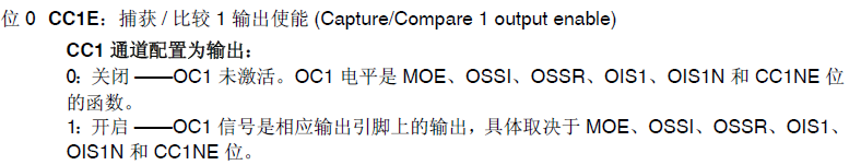
通过将对应通道的寄存器置1,从而使能对应通道的比较寄存器。
使用
在使用中,本程序只是修改PWM的占空比,这也是最常用的功能。其源程序为:
/**
 * @brief 修改比较值
 * @note 无
 * @param {*}比较值
 * @retval 无
 */

void TIM_SetTIM3Compare4(u32 compare)
{
    TIM3->CCR4 = compare;
}
可以看到,本程序实现非常简单,即直接向寄存器中写入数值。然而,在库函数中其实是有提供宏定义来实现该功能的。宏定义为:
/**
  * @brief  Set the TIM Capture Compare Register value on runtime without calling another time ConfigChannel function.
  * @param  __HANDLE__ TIM handle.
  * @param  __CHANNEL__ TIM Channels to be configured.
  *          This parameter can be one of the following values:
  *            @arg TIM_CHANNEL_1: TIM Channel 1 selected
  *            @arg TIM_CHANNEL_2: TIM Channel 2 selected
  *            @arg TIM_CHANNEL_3: TIM Channel 3 selected
  *            @arg TIM_CHANNEL_4: TIM Channel 4 selected
  * @param  __COMPARE__ specifies the Capture Compare register new value.
  * @retval None
  */
#define __HAL_TIM_SET_COMPARE(__HANDLE__, __CHANNEL__, __COMPARE__) \
  (((__CHANNEL__) == TIM_CHANNEL_1) ? ((__HANDLE__)->Instance->CCR1 = (__COMPARE__)) :\
   ((__CHANNEL__) == TIM_CHANNEL_2) ? ((__HANDLE__)->Instance->CCR2 = (__COMPARE__)) :\
   ((__CHANNEL__) == TIM_CHANNEL_3) ? ((__HANDLE__)->Instance->CCR3 = (__COMPARE__)) :\
   ((__HANDLE__)->Instance->CCR4 = (__COMPARE__)))
然而,个人不是很推荐,理由如下:
- 效率比较低。
- 必须使用定时器句柄结构体变量,增加全局变量。


 945
945

 被折叠的 条评论
为什么被折叠?
被折叠的 条评论
为什么被折叠?
 到【灌水乐园】发言


