


hello,大家好,这里是xddcore,今天中午又花了一个小时左右,模仿CD4017,捏了个十进制计数器。
前言
什么是十进制计数器(/CD4017)?
CD4017:十进制计数器/脉冲分配器
INH 为低电平时,计数器在时钟上升沿计数;反之,计数功能无效。CR 为高电平时,计数器清零。
Johnson 计数器,提供了快速操作、2 输入译码选通和无毛刺译码输出。防锁选通,保证了正确的计数顺序。译码输出一般为低电平,只有在对应时钟周期内保持高电平。在每10 个时钟输入周期CO 信号完成一次进位,并用作多级计数链的下级脉动时钟。
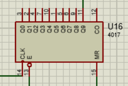
引脚定义
Qx, //计数脉冲输出端
CO, //进位脉冲输出端
CLK, //时钟输入端
E, //INH计数使能端(低电平有效)
MR //CR计数清除端(低电平有效)
真值表

ps:INH=E,CR=MR
Verilog程序
`timescale 1ns / 1ns

module decimal_counter(
	Qx, //计数脉冲输出端
	CO, //进位脉冲输出端
	CLK, //时钟输入端
	E, //INH计数使能端(低电平有效)
	MR //CR计数清除端(低电平有效)
	);

//===========================================================================
// 端口声明与寄存器定义
//===========================================================================
input CLK; //时钟输入端
input E; //INH计数使能端(低电平有效)
input MR; //CR计数清除端(低电平有效)

output [9:0] Qx; //计数脉冲输出端
output CO; //进位脉冲输出端(Q0-Q4:CO=1;Q5-Q9:CO=0)

reg [9:0] Qx = 10'b00000_00001; //初始状态
reg CO;

reg E_last; //上一拍的E

//===========================================================================
// 主体逻辑
//===========================================================================
always @(*) //任何敏感信号变化都会触发
	begin
		if({E,MR} == 2'bx1)//复位
			begin
				Qx <= 10'b00000_00001;
			end
		else if({E,MR} == 2'b10) //保持原来状态,停止计数
			begin

			end
	end

always @(posedge CLK) //检测时钟信号上升沿
	begin
		E_last <= E;
		if({E,MR} == 2'b00 || ((MR == 1'b0) &&((E_last == 1'b1) && (E == 1'b0))) ) //计数
			begin
				Qx <= Qx << 1;
				if(Qx == 10'b00000_00000)
					begin
						Qx <= 10'b00000_00001;
					end
				if(Qx<=10'b00000_10000)//只有计数脉冲发生改变时,才改变CO输出,提高效率
					begin
					CO <= 1'b1;
					end
				else if(Qx>=10'b00001_00000)
					begin
					CO <= 1'b0;
					end
			end
	end

endmodule
TestBench
// Copyright (C) 2017  Intel Corporation. All rights reserved.
// Your use of Intel Corporation's design tools, logic functions
// and other software and tools, and its AMPP partner logic
// functions, and any output files from any of the foregoing
// (including device programming or simulation files), and any
// associated documentation or information are expressly subject
// to the terms and conditions of the Intel Program License
// Subscription Agreement, the Intel Quartus Prime License Agreement,
// the Intel FPGA IP License Agreement, or other applicable license
// agreement, including, without limitation, that your use is for
// the sole purpose of programming logic devices manufactured by
// Intel and sold by Intel or its authorized distributors.  Please
// refer to the applicable agreement for further details.

// *****************************************************************************
// This file contains a Verilog test bench template that is freely editable to
// suit user's needs .Comments are provided in each section to help the user
// fill out necessary details.
// *****************************************************************************
// Generated on "08/04/2020 13:20:15"

// Verilog Test Bench template for design : decimal_counter
//
// Simulation tool : ModelSim-Altera (Verilog)
//

`timescale 1ns / 1ns
module decimal_counter_tb();
// constants
// general purpose registers
reg eachvec;
// test vector input registers
reg CLK;
reg E;
reg MR;
// wires
wire CO;
wire [9:0]  Qx;

	// assign statements (if any)
	decimal_counter i1 (
	// port map - connection between master ports and signals/registers
		.CLK(CLK),
		.CO(CO),
		.E(E),
		.MR(MR),
		.Qx(Qx)
	);
	initial
		begin
			$display("Running Decimal Counter testbench");
			//开始计数
			E <= 1'b0;
			MR <= 1'b0;
			CLK <= 1'b0;
		end

	always #20 CLK <= ~CLK; //生成周期40ns的clk信号

endmodule
RTL仿真结果

结论
收工,明天把4个D类触发器和两个十进制计数器捏到一起,就组成个BCD Generator了


 493
493


 被折叠的 条评论
为什么被折叠?
被折叠的 条评论
为什么被折叠?
 到【灌水乐园】发言


