


在本章中,我们来探索如何实施前几章中提到的网络虚拟化解决方案。我们尤其要考察一下Overlay 虚拟网络的配置。第 16 章中涉及的 EVPN 属于控制协议,VXLAN是封装协议。针对VRF的OSPF和BGP的配置已分别在“对VRF的支持部分和“BGP和VRF”部分有所涉及。
本章中将解决如下关键问题:
- 如何在自己的网络中配置 EVPN 的桥接和路由?
- 如何针对网络虚拟化配置关键的路由协议 (eBGP、iBGP 和OSPF) ?
配置场景
本章中涉及如下三种高层级的配置:
- 对 Underlay 网络和Overlay 网络的单一eBGP会话
- OSPF用于物理网络,入口流量复制协同iBGP 用于 Overlay 网络
- OSPF用于物理网络,以路由方式进行的Underlay 网络多播协同iBGP用于Overlay 网络。
根据第 16 章的推荐,EVPN的配置假设是基于一种分布式的、对称的路由模型。但是,本章会指出对称和非对称路由配置之间的差异,集中式和分布式路由配置之间的差异,以及路由和桥接的配置之间的差异。由于原生的Linux 并不支持 (只有 Cumulus Linux 支持)路由方式的Underlay网络多播,因此在设备本地配置中将不会展示这种 Underlay 网络的配置。由于其他一些原因PIM-SM配置是很有用的,所以将会演示该配置。
将使用图 17-1 所示的网络拓扑来编写配置。我们假设使用 MLAG 将服务器通过双连接的方式连接到leaf 交换机。图中演示的出口 leaf交换机用于提供EVPN网络连接到外部网络的相关信息。我们会在任何可能的地方使用无编号 BGP和OSPF。从出口 leaf 交换机到防火墙和边缘路由器的接口是已编号接口,因为边缘路由器和防火墙极有可能不支持无编号 BGP。
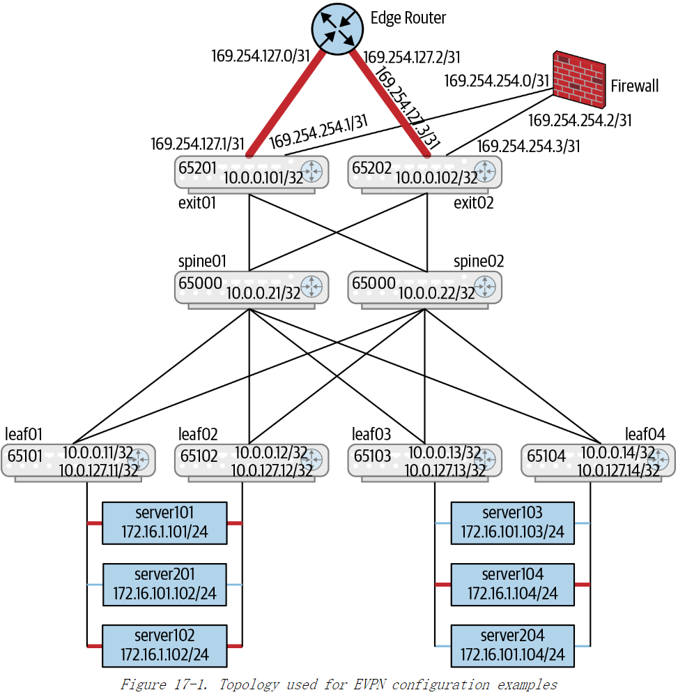
这里还得再提一下 VRF的使用。所有的 EVPN 网络内部的IP路由都与 VRF 关联。所有的MAC地址都与VNI关联。一组 VNI被映射到一个 VRF,且此 VRF 与唯一一个VNI相关联的。VRF 在这一点上与 VLAN 类似:VRF 只在本地配置,而在全局范围内,VLAN和VRF都被映射到他们各自的唯一的 VNI上。VRF和一个三层VNI相关联,而VLAN和一个二层的 VNI相关联。Underlay 网络使用缺省VRF。
黑色标识的 VRF是内部网络,被称为 evpn-vrf。 红色标识的 VRF 连接到外部网络的部分,称为 internet-vrf。流量必须经过防火墙才能从一个 VRF到达另一个 VRF。Underlay 网络处在缺省 VRF 中。黑色标识的 VRF 链路和缺省的 VRF 链路看起来并无区别。黑色标识的 VRF内传输的数据包是 VXLAN 协议封装的数据包,而Underlay 网络的数据包不是 VXLAN 封装的数据包。
设备本地配置
leaf01的配置信息
auto all
iface lo inet loopback
  address 10.0.0.11/32                                 #1
  clagd-vxlan-anycast-ip 10.0.0.112                    #2
  vxlan-local-tunnelip 10.0.0.11                       #3

iface vni13                                            #4
  mtu 9164                                             #5
  vxlan-id 13                                          #6
  bridge-access 13                                     #7
  bridge-learning off                                  #8

iface vni24                                            #4
  mtu 9164                                             #5
  vxlan-id 24                                          #6
  bridge-access 24                                     #7
  bridge-learning off                                  #8

iface vlan13                                           #9
    mtu 9164
    address 10.1.3.11/24                               #10
    address-virtual 44:39:39:ff:00:13 10.1.3.1/24      #11
    vlan-id 13                                         #12
    vlan-raw-device bridge
    vrf evpn-vrf                                       #13

iface vlan24
    mtu 9164
    address 10.2.4.11/24                               #10
    address-virtual 44:39:39:ff:00:13 10.2.4.1/24      #11
    vlan-id 24                                         #12
    vlan-raw-device bridge                             #13
    vrf evpn-vrf                                       #14

#
# This is the L3 VNI definition that we need for symmetric configuration.
# This is used to transport the EVPN-routed packet between the VTEPs.
#
iface vxlan4001                                        #15
    vxlan-id 104001
    bridge-access 4001
#
iface vlan4001                                         #16
    hwaddress 44:39:39:FF:40:94
    vlan-id 4001
    vlan-raw-device bridge
    vrf evpn-vrf
#
配置的详细解释:
1)如果此处你使用 ifupdown2 定义了 IP 地址,则不要在 FRR 配置里再次定义。
2)这里配置了 Cumulus 相关的 MLAG 实现 CLAG,定义了共享的 VXLAN隧道源端IP 地址。其他供应商针对他们各自的 MLAG 实现,提供了关于此项配置的各自版本。由于存在双连接的服务器,所以此配置是必要的。
3)此处指出当 CLAG 无法运行时,将会使用本地的源端隧道IP地址。当 CLAG正常运行时,在标号 2 处给出的地址被用作隧道源端IP地址。注:此处和16章中矛盾,之前描述 10.0.127.11为leaf01的VTEP IP。
4)每一个VXLAN的VNI由 Linux 内核里的一个设备来代表。从Linux 内核4.14开始支持单一设备用于代表所有的 VNI。但是,这种模型并没有被生态系统中的其他部分所支持 (比如,无法配置 vlan-vni 映射) ,所以这里将不展示了。
5)VXLAN隧道接口推荐使用超大帧,所以我们设定接口的 MTU为9164。
6)此处定义与设备相关联的 VNI
7)此处将VNI映射到本地VLAN ID这种情况下,此映射能起到一种身份认证功能。
8)因为我们使用了 EVPN,不希望启动远端 MAC 地址学习功能。所以,这里也禁用了针对 VNI的学习。
9)此处为VNI定义了 SVI,节点会为这些 VNI 而支持路由功能。
在VXLAN架构中,SVI用于在VXLAN的二层网络和三层网络之间进行路由。每个Leaf节点通常会为每个VLAN配置一个SVI接口,每个 SVI 都代表一个特定的 VLAN,并为该 VLAN 分配一个 IP 地址,充当 VLAN 中所有设备的默认网关。通过这些SVI,Leaf节点可以为VXLAN中的设备提供三层的路由功能。这种功能通常称为 分布式网关(Distributed Anycast Gateway),实现了各个Leaf节点能够为它们管理的VXLAN网络中的设备提供路由服务。
10)此处是该 leaf 交换机在指定 VNI 上的唯一IP地址。
11)此处是该VNI的二级网关IP地址。此地址由所有携带此 VNI的leaf交换机共享。服务器使用此IP 地址作为缺省网关地址,以便能在不更改其缺省网关配置的情况下连接到任何机架。
12)此处表明用于该 VLAN 的接口是 SVI。
13)Linux 允许多个 802.1Q 的网桥存在于同一台网络设备上。一个网络接口只会被分配给其中一个网桥,因此网络链路上所使用的 VLAN 是一目了然的。比如,我们曾在第 7章中见到过容器是如何使用此类含有多个网桥的模型。因此,个SVI需要被关联至某个特定的网桥。这一行就是实现此功能的。
14)此处表明此 SVI是该 VRF的一部分。
15)此处是对称路由的三层 VNI
16)此处仅是该三层 VNI的一个本地实例。
vxlan4001定义了一个用于三层路由的L3 VNI,通过104001这个VNI进行跨Leaf节点的三层流量传输。vlan4001将VLAN 4001映射到L3 VNI,实现VLAN和VNI之间的关联,并且通过VRF隔离不同租户或网络实例的路由表。
单一eBGP会话
本节开始我们会展示一些交换机的完整配置,分别是一台leaf交换机、一台 spine交换机以及一台出口 leaf交换机。示例17-1 展示了它们在 FRR 中的配置。
示例17-1 基于单一eBGP会话模型的对称路由的FRR配置示例
Configuration for spine01
interface lo
  ip address 10.0.0.21/32
!
router bgp 65000
    bgp router-id 10.0.0.21
    bgp bestpath as-path multipath-relax
    neighbor peer-group ISL
    neighbor ISL remote-as external
    neighbor swp1 interface peer-group ISL
    neighbor swp2 interface peer-group ISL
    neighbor swp3 interface peer-group ISL
    neighbor swp4 interface peer-group ISL
    neighbor swp5 interface peer-group ISL
    neighbor swp6 interface peer-group ISL
    address-family ipv4 unicast
        neighbor ISL activate
        redistribute connected route-map LOOPBACKS
    address-family l2vpn evpn
        neighbor ISL activate                                         #1
!
route-map LOOPBACKS permit 10
    match interface lo
!
1)spine 交换机通过激活l2vpn evpn地址族向其对等设备发出信号,表明此 spine交换机可以处理 EVPN路由。这并不是说 spine 交换机正在参与 Overlay 网络的运作。此处的配置对于所有交换 EVPN 信息的节点都是必需的。
Configuration for leaf01
interface lo
   ip address 10.0.0.11/32
!
! This VRF definition is needed only for symmetric EVPN routing configuration
vrf evpn-vrf                                                          #2
      vni 104001
!
router bgp 65011
    bgp router-id 10.0.0.11
    bgp bestpath as-path multipath-relax
    neighbor fabric peer-group
    neighbor fabric remote-as external
    neighbor swp1 interface peer-group fabric
    neighbor swp2 interface peer-group fabric
    address-family ipv4 unicast
        neighbor fabric activate
        redistribute connected route-map LOOPBACKS
    !
    address-family l2vpn evpn
        neighbor fabric activate
        advertise-all-vni                                             #3
  advertise-svi-ip                                                    #4
    !
!
route-map LOOPBACKS permit 10                                         #5
    match interface lo
!
2)此处 VRF的定义用于将对称路由配置和非对称路由配置区分开来。此定义指定了用于 VRF的三层 VNI。此处的映射等效于 VLAN-VNI的映射。此行配置对于对称路由是必需的,这一点在“路由通告”中已经描述。
3)此处是在 leaf 交换机上的单行配置,用于启动 EVPN 信息的通告,尤其是 RT-2和 RT-3 路由。该配置只会出现在 leaf 交换机 (出口交换机或者常规交换机)
4)你需要用此行配置来允许 evpn-vrf 上的各个leaf交换机运行 ping、traceroute以及类似的网络管理指令。请记住在分布式路由场景中,对于本地部署的 VLAN来说,所有的leaf交换机共享公共的网关地址。在本例中,对于归属于本地所有 leaf 交换机的 VLAN13 和 24,所有的 leaf 交换机将 10.1.3.1/24 和 10.2.4.1/24作为缺省网关地址。此外,每个leaf交换机在那些子网范围内有其各自唯一的IP 地址。举例来说,在 VLAN13 内,leaf01 具有地址 10.1.3.11,leaf02具有地址 10.1.3,12等。此行配置正是将此唯一的 IP 地址和此IP地址对应的 MAC地址进行通告。所有 leaf 交换机公用的 IP 地址并不会被通告。
5)与简易的使用路由方式的 Clos 网络不同,并不存在需要借助路由重发布来通告的服务器子网,因为子网路由不再局限于单个机架 /leaf交换机。各个用于服务器子网的/32路由作为 EVPN RT-2路由被通告。
Configuration for exit01
!
interface lo
  ip address 10.0.0.101/32
!
interface swp3
  ip address 169.254.127.1/31
!
interface swp4.2
  ip address 169.254.254.1/31
!
interface swp4.3
  ip address 169.254.254.3/31
!
interface swp4.4
  ip address 169.254.254.5/31
!
vrf evpn-vrf
   vni 104001
!
! default VRF peering with the underlay and the firewall
!
router bgp 65201                                                      #6
    bgp router-id 10.0.0.101
    bgp bestpath as-path multipath-relax
    neighbor fabric peer-group
    neighbor fabric remote-as external
    ! These two are peering with the spine
    neighbor swp1 interface peer-group fabric
    neighbor swp2 interface peer-group fabric
    ! This is peering with the firewall to announce the underlay
    ! routes to the edge router (via the firewall) and receive the
    ! default route from the edge router (also via the firewall)
    neighbor swp4.2 interface remote-as external
    address-family ipv4 unicast
        neighbor fabric activate
  neighbor swp4.2 activate
        neighbor swp4.2 allowas-in 1                                  #7
        redistribute connected route-map LOOPBACKS
    !
    address-family l2vpn evpn
        neighbor fabric activate
        advertise-all-vni                                             #3
    !
!
route-map LOOPBACKS permit 10
    match interface lo
!
! evpn vrf peering to announce default route to internal net
!
router bgp 65201 vrf evpn-vrf                                         #8
    bgp router-id 10.0.0.101
    neighbor swp4.3 interface remote-as external
    address-family ipv4 unicast
       neighbor swp4.3 activate
       ! The following two network statements are for
       ! distributing the summarized route to the firewall
       aggregate-address 10.1.3.0/24 summary-only                     #9
       aggregate-address 10.2.4.0/24 summary-only
       neighbor swp4.3 allowas-in 1
    exit-address-family
    !
    ! This config ensures we advertise the default route
    ! as a type 5 route in EVPN in the main BGP instance.
    ! The firewall peering is to get the default route
    ! in the evpn-vrf from the internet-vrf. Firewall
    ! does not peer for l2vpn/evpn.
    !
    address-family l2vpn evpn                                         #10
      advertise ipv4 unicast
!
! internet vrf peering to retrieve the default route from the
! internet facing router and give it to the firewall.
!
router bgp 65201 vrf internet-vrf                                     #11
    bgp router-id 10.0.0.101
    bgp bestpath as-path multipath-relax
    neighbor internet peer-group
    neighbor internet remote-as external
    neighbor swp4.4 interface peer-group internet
    neighbor swp3 interface peer-group internet
    address-family ipv4 unicast
        neighbor internet activate
        neighbor swp4.4 allowas-in 1
  neighbor swp3 remove-private-AS                                     #12
        redistribute connected route-map INTERNET
    !
!
route-map INTERNET permit 10
    match interface internet-vrf
!----
6)此处是出口 leaf交换机上的三个 BGP 段的第一个。此段配置用于处理 Underlay网络以及接收来自其余 leaf 交换机的 EVPN路由。此段配置也与防火墙以对等方式共同工作,确保 Underlay 网络获取到缺省路由。如果 Underlay 网络与边缘路由器完全隔离,那么通过去除与防火墙的对等关系的方法,和/或添加适当的防火墙规则的方法,你也可以让 Underlay 网络获取到缺省路由。
7)但是需要再指出的一点是,即便当设备被分配了一个IP 地址,以及设备可能与并不支持无编号 BGP 的相邻设备形成对等关系时,仍要使用此网络接口名。FRR 可以智能的查找到此网络接口的IP地址,如果此IP 地址属于/31 或者/30 子网,还能够查找到此网络接口的对等接口的IP地址。这是因为/31和/30子网只能有两个可用的端点IP 地址,因此如果你知道其中一个,则可以自动推断出另一个。比如,169.254.254.0/31 子网拥有可用地址为169.254.0.0和69.254.0.1。
8)此处是出口 leaf 交换机上的VRF 配置,用于通告在 evpn-vrf VRF 的缺省路由。此缺省路由是经过防火墙从 Internet 上学习得到的。
9)此行指示 BGP 只通告汇总路由 10.1.3.0/24,并且仅当此子网中至少存在一条路由时才会这样做。外部网络并不需要知道如何抵达每一台特定的主机。因为出口leaf 交换机毕竟也是交换机,它们可以正确的对路由进行汇总。与此行类似的其他行仍然包含有特定的IP 地址,但这是有必要的,因为这类信息是某种策略的一部分,而且并不容易自动决定。再者,这对于管理员来说并不是很大的负担,因为这些行中的配置只是用于出口leaf交换机。这些行里的配置对所有的出口 leaf交换机都是通用的,这也可以看作是对自动化的额外辅助。
10)此处将使用EVPN RT-5 路由通告缺省路由。本段并没有有效的声明,因为在此VRF中不存在可以与EVPN路由相交换的相邻设备。请记住,RT-5 路由在Underlay 网络的 BGP 会话中被通告。在我看来,这是某种配置的一个例子,此配置能够暗示其实现方式,或者是从此配置中推导出实现方式,而不是让用户从自己的角度来构建。
11)此处是VRF配置用于配置 internet-vrf 与边缘路由器相连的接口,该接口用来建立与外部网络的连接。internet-vrf 没有 EVPN配置,因此不必为internet-vrf 定义三层VNI,这一点正如我们在前面第二处对evpn-vrf 所做的那样。
12)此处的配置是在通告到边缘路由器的路由之前,将所有的私有 ASN 都剥离掉。
当VXLAN作为虚拟Overlay 网络时,BGP并不需要针对每个 VRF都建立与其对等的实体,因为数据包中的 VNI已经将此信息进行了编码。然而在出口 leaf 交换机上,其与边缘路由器之间,以及与防火墙之间建立对等关系时,并未使用VXLAN的方式进行封装,而是使用了逐跳 (hop-by-hop) VRF 模型。
非对称路由配置最近增加了使用三层 VNI的支持,以便允许 IP 前缀的分发,例如缺省路由的分发。如果你只想在 leaf 交换机上使用 EVPN 桥接,则对应的配置看起来和展示的那种配置一样,但是缺少了为 leaf 交换机上的 VNI子网定义 SVI,而且也没有了 VRF-VNI之间映射的定义。还有,如果你所需要的只是 EVPN桥接,那么advertise-svi-ip 也不需要了。如果你使用的是集中式路由,并且把出口 leaf交换机当作路由器使用,以及仅在 leaf 交换机中使用 EVPN桥接,那么exit01的配置则看起来如示例17-2 所示。
示例17-2:针对集中式路由的exit01的FRR 配置
router bgp 65201
    bgp router-id 10.0.0.101
    bgp bestpath as-path multipath-relax
    neighbor fabric peer-group
    neighbor fabric remote-as external
    neighbor swp1 interface peer-group fabric
    neighbor swp2 interface peer-group fabric
    ! This is peering with the firewall to announce the underlay
    ! routes to the edge router (via the firewall) and receive the
    ! default route from the edge router (also via the firewall)
    neighbor swp4.2 remote-as external
    address-family ipv4 unicast
        neighbor fabric activate
        neighbor swp4.2 allowas-in 1
        redistribute connected route-map LOOPBACKS
    !
    address-family l2vpn evpn
        neighbor fabric activate
        advertise-all-vni
        advertise-default-gw                                          #1
    !

!
route-map LOOPBACKS permit 10
    match interface lo
!
! evpn vrf peering to steer internal traffic through firewall
! for external connectivity
!
router bgp 65201 vrf evpn-vrf                                         #2
    bgp router-id 10.0.0.101
    neighbor swp4.3 remote-as external
    address-family ipv4 unicast
       neighbor swp4.3 activate
       ! The following two network statements are for
       ! distributing the summarized route to the firewall
       aggregate-address 10.1.3.0/24 summary-only
       aggregate-address 10.2.4.0/24 summary-only
       neighbor swp4.3 allowas-in 1
    exit-address-family

router bgp 65201 vrf internet-vrf
    bgp router-id 10.0.0.101
    bgp bestpath as-path multipath-relax
    neighbor internet peer-group
    neighbor internet remote-as external
    neighbor swp3 interface peer-group internet
    neighbor swp4.4 interface peer-group internet
    address-family ipv4 unicast
        neighbor internet activate
        neighbor swp4.4 allowas-in 1
        redistribute connected route-map INTERNET
!
route-map INTERNET permit 10
    match interface internet-vrf
!
1)此处会通过 RT-2 路由将缺省路由器的 MAC 地址通告给 leaf 交换机。此MAC路由携带了路由器 MAC扩展团体(Router MAC Extended Community)。
2)由于路由仅发生在出口 leaf交换机上,因此任何通过防火墙学习自 evpn-vrf的EVPN路由都无需向内部网络通告。所以,在此处的建立对等关系的会话中,不存在二层 VPN/evpn地址族配置。
使用 allowas-in 1 的原因
让我们讨论一下为什么需要新的 BGP 的选项 allowas-in 1。回想一下防火墙和某个出口 leaf 交换机之间会有多个连接,每个 VRF里都有一个连接。但是,防火墙本身是感知不到 VRF的,而且仅能看到多个 BGP会话。当防火墙将从一个VRF 内的相邻设备学习的路由反射到另一个 VRF 中的相邻设备时,由于BGP ASPATH 的环路检测,导致出口 leaf 交换机的 BGP会拒绝这些路由。为了更好的理解,参见图 17-2。
图17-2:VRF AS_PATH 环路示例
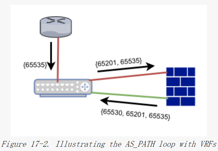
箭头显示了AS_PATH首先由边缘路由器通过一条路由被通告,由internet-vrf里的出口leaf 交换机接收。接着,AS_PATH被传递到internet-vrf里的防火墙,并被接收到evpn-vrf里。如图 17-2 所示,AS_PATH以边缘路由器的ASN65535 开头。当从evpn-vrf 里的防火墙返回到出口leaf 交换机时,出口leaf 交换机的ASN65201 会出现在AS_PATH中。所以,exit01 将会拒绝此AS_PATH,因为它检测到了环路。如果你启动了exit01 上的调试功能,你会在日志中看到类似下面的一条消息:
2018-04-13T06:19:04.101100+00:00 exit01 bgpd[4112]: 169.254.253.0
rcvd UPDATE about 0.0.0.0/0 -- DENIED due to: as-path contains our own AS;
2018-04-13T06:19:04.101380+00:00 exit01 bgpd[4112]: 169.254.253.0
rcvd UPDATE w/ attr: , origin ?, mp_nexthop
fe80::4638:39ff:fe00:4a(fe80::4638:39ff:fe00:4a)(fe80::4638:39ff:fe00:4a),
path 65530 65201 65535
为了避免此路由被丢弃,需要添加 allowas-in 1的选项。此选项告诉 BGP在ASPATH环路检测中忽略自身 ASN 的单次出现这种情况。因为我们只想在防火墙建立对等连接时使用这种特定配置,尤其是针对防火墙会话使用这种配置、而且并不针对对等设备群组整体使用这种配置
你或许观察到 spine 交换机和 leaf 交换机上的路由将包含 AS_PATH {65201, 65530, 65201, 65535}。当你看到环路时,为什么 spine 交换机和 leaf 交换机不拒绝这条路由呢?这是因为 BGP AS_PATH环路检测仅仅测试BGP路由器的ASN是否已经存在 AS_PATH 中。它并不会尝试检测是否有其他ASN 的副本。
二层 VNI 与 三层 VNI 的对比
| 特性 | 二层 VNI (L2 VNI) | 三层 VNI (L3 VNI) |
|---|---|---|
| 主要功能 | 扩展二层网络,连接同一虚拟网络的设备 | 提供三层路由,连接不同二层网络 (L2 VNI) |
| 数据转发层 | 二层 (L2),基于 MAC 地址 | 三层 (L3),基于 IP 地址 |
| 广播域 | 是,支持二层广播、未知单播和多播流量(BUM) | 否,不涉及二层广播域 |
| 流量类型 | 二层以太网帧 | 三层 IP 数据包 |
| 使用场景 | 虚拟化环境下的二层隔离、二层网络的扩展 | 不同二层网络之间的三层路由、跨子网通信 |
| 依赖协议 | EVPN/BGP 控制平面进行 MAC 地址分发 | EVPN/BGP 控制平面进行 IP 路由分发 |
OSPF 用于 Underlay 网络,iBGP 用于Overlay 网络
在此情况下,Underlay 络使用OSPF 无编号配置已经在第 13 章的示例13-3 中描述过了。与该配置的主要区别在于,我们不会像在纯 Underlay 情况下那样在 OSPF中发布服务器子网地址。我们仅仅通告回环IP 地址,包括VTEP的IP 地址。一些路由软件将 VTEP的IP 地址分配给回环设备以外的其他网络设备,在这种情况下,你必须确保OSPF 会将此 IP 地址的可达性也一同通告。
Example 17-3. FRR configuration for leaf01 and spine01 with iBGP
Configuration for spine01
interface lo
  ip ospf area 0
  ip address 10.0.0.21/32
!
interface swp1
  ip ospf network point-to-point
  ip ospf area 0
  ip address 10.0.0.21/32
!
interface swp2
  ip ospf network point-to-point
  ip ospf area 0
  ip address 10.0.0.21/32
!
interface swp3
  ip ospf network point-to-point
  ip ospf area 0
  ip address 10.0.0.21/32
!
interface swp4
  ip ospf network point-to-point
  ip ospf area 0
  ip address 10.0.0.21/32
!
interface swp5
  ip ospf network point-to-point
  ip ospf area 0
  ip address 10.0.0.21/32
!
interface swp6
  ip ospf network point-to-point
  ip ospf area 0
  ip address 10.0.0.21/32
!
router ospf
  ospf router-id 10.0.0.21
  passive-interface lo
!
router bgp 65000
  bgp router-id 10.0.0.21
  bgp bestpath as-path multipath-relax
  neighbor RR peer-group
  neighbor RR remote-as internal                                      #1
  neighbor RR advertisement-interval 0
  neighbor RR timers 3 10
  neighbor RR timers connect 5
  neighbor swp1 interface peer-group RR
  neighbor swp2 interface peer-group RR
  neighbor swp3 interface peer-group RR
  neighbor swp4 interface peer-group RR
  neighbor swp5 interface peer-group RR
  neighbor swp6 interface peer-group RR
!
  address-family ipv4 unicast
   neighbor RR route-reflector-client                                 #2
   neighbor RR activate
   maximum-paths ibgp 16                                              #3
  exit-address-family
!
  address-family l2vpn evpn
   neighbor RR route-reflector-client                                 #2
   neighbor RR activate
  exit-address-family
!
Configuration for leaf01
interface lo
  ip ospf area 0
  ip address 10.0.0.11/32
!
interface swp1
  ip ospf network point-to-point
  ip ospf area 0
  ip address 10.0.0.11/32
!
interface swp2
  ip ospf network point-to-point
  ip ospf area 0
  ip address 10.0.0.11/32
!
vrf evpn-vrf
  vni 104001
!
router ospf
  ospf router-id 10.0.0.11
  passive-interface lo
!
router bgp 65000
  bgp router-id 10.0.0.11
  neighbor RR peer-group
  neighbor RR remote-as internal                                      #1
  neighbor RR advertisement-interval 0
  neighbor RR timers 3 10
  neighbor RR timers connect 5
  neighbor swp1 interface peer-group RR
  neighbor swp2 interface peer-group RR
!
  address-family l2vpn evpn
    neighbor RR activate
    advertise-all-vni
    advertise-svi-ip
  exit-address-family
!
Configuration for exit01
interface lo
  ip ospf area 0
  ip address 10.0.0.101/32
!
interface swp1
  ip ospf network point-to-point
  ip ospf area 0
  ip address 10.0.0.101/32
!
interface swp2
  ip ospf network point-to-point
  ip ospf area 0
  ip address 10.0.0.101/32
!
interface swp3
  ip ospf network point-to-point
  ip ospf area 0
  ip address 10.0.0.101/32
!
interface swp3
  ip address 169.254.127.1/31
!
interface swp4.2
  ip address 169.254.254.1/31
!
interface swp4.3
  ip address 169.254.254.3/31
!
interface swp4.4
  ip address 169.254.254.5/31
!
interface vrf evpn-vrf
 vni 104001
!
router ospf
  ospf router-id 10.0.0.101
  passive-interface lo

router bgp 65000
 bgp router-id 10.0.0.101
 neighbor swp4.2 interface remote-as internal
 neighbor RR peer-group
 neighbor RR remote-as internal
 neighbor RR advertisement-interval 0
 neighbor RR timers 3 10
 neighbor RR timers connect 5
 neighbor swp1 interface peer-group RR
 neighbor swp2 interface peer-group RR
 !
 address-family ipv4 unicast
   redistribute ospf                                                  #4
   maximum-paths ibgp 16
 exit-address-family
 address-family l2vpn evpn
  neighbor RR activate
  advertise-all-vni
 exit-address-family
!
router bgp 65000 vrf evpn-vrf
 bgp router-id 10.0.0.101
 neighbor swp4.3 interface remote-as external
 !
 address-family ipv4 unicast
  aggregate-address 10.1.3.0/24 summary-only
  aggregate-address 10.2.4.0/24 summary-only
 exit-address-family
 !
 address-family l2vpn evpn
  advertise ipv4 unicast
 exit-address-family
!
router bgp 65001 vrf internet-vrf                                     #5
 bgp router-id 10.0.0.101
 neighbor swp4.4 interface remote-as external
 neighbor swp3 interface remote-as external
!
1)此处的配置表明这是一个通过 remote-as internal 实现的 iBGP 的对等互联。
2)此处将 spine 交换机配置为一个iBGP 路由反射器。如果没有此配置项,则EVPN 路由将无法分发至 leaf 交换机。
3)此处配置对于使用iBGP 启动 ECMP 是必需的。只有非 EVPN 地址族需要此处的配置。EVPN 并不支持 ECMP,因为 MAC表并不支持 ECMP。
4)因为所有的 Underlay 网络路由是借助 OSFP 学习到的,为了让边缘路由器可
以看到 OSPF路由,你必须使这些路由能够重分发至iBGP 中,这也会使得
Underlay 网络的leaf和 spine 交换机能够访问Internet。此行配置指出为了实
leaf 交换机与边缘路由器进行通信所需要做的事。但是更为安全的配置是防止
各个leaf 和 spine 交换机访问外部网络。为达到此目的,你可以通过阻止eaf和
spine 交换机所在子网被通告至边缘路由器所连接的外部网络,或者通过去掉你
的配置中的重分发配置项。
5)在internet-vrf 上使用一种不同ASN来避免“使用选项allowas-in 1的原因“一节所描述的问题。
因为OSPF用于通告 Underlay 网络可达性,包括VTEP,所以我们不会通过iBGP再通告。
在数据中心内,出口 leaf交换机也使用OSPF通告 Underlay 网络可达性,并使用iBGP 用于EVPN的信息。在本节,出口leaf 交换机使用和边缘路由器与防火墙同样的配置。
allowas-in 与ASN 分离
与eBGP 配置不同,iBGP 配置并不使用 allowas-in 1 配置项以便当穿越防火墙切换 VRF时,确保 BGP 会接受这些路由。为了理解其原因,请回忆一下AS_PATH环路检测是如何工作的。每一个接收到路由通告的 BGP路由器都会检测以确保其自身的 ASN 并未出现在AS_PATH中。当使用eBGP时,出口 leaf 与 spine 交换机与常规交换机有不同的ASN,因此只有出口 leaf 交换机需要添加 allowas-in 1 配置项。但是当使用iBGP时,spine 和leaf 交换机与出口交换机有同样的 ASN,所以还需要在那些设备上引人allowas-in 1配置项。这样做是有问题的,因为我们可能最终也会错误的接受真实存在的环路路由。仅仅在出口 leaf 交换机上引 allowas-in 1配置项是一种在特定情况下的非常克制的做法。如果随处使用 iBGP 配置,是会带来负面影响的。为了避免这种情况,我们采取了另一种技巧。
FRR (以及一些其他的流行路由协议栈) 支持特定 BGP VRF会话在出口 leaf交换机上使用不同的 ASN(65001)。这使得我们避免了 AS_PATH 环路问题。接收方,比如说exit01,从防火墙接收的缺省路由的AS_PATH 会是{65530,65001,65535}。这种模型仅仅在出口 leaf 交换机上更改配置,而且它有助于保存一份干净的AS_PATH,这对定位问题很有帮助。
为了避免使用 allowas-in 1,在eBGP 中是否可以使用不同的ASN呢?其实是可以这样做的。
PIM/MSDP 配置
当启动路由方式的多播的 Underlay 网络来处理 BUM 数据包时,让我们来看一下其相关配置。正如在“EVPN桥接与路由多播的Underlay 网络”一节所描述的那样,我们使用 PIM-SM作为具有任播 RP的多播路由协议。MSDP是一种用于在spine交换机之间进行多播 RP 路由状态同步的协议。
示例17-4:用于 EVPN的 PIM/MSDP的FRR 配置样例
Configuration for spine01
interface lo
  ip ospf area 0
  ip address 10.0.0.21/32
  ip address 10.0.10.1/32                                             #1
  ip pim                                                              #2
!
interface swp1
  ip ospf network point-to-point
  ip ospf area 0
  ip pim
!
interface swp2
  ip ospf network point-to-point
  ip ospf area 0
  ip pim
!
interface swp3
  ip ospf network point-to-point
  ip ospf area 0
  ip pim
!
interface swp4
  ip ospf network point-to-point
  ip ospf area 0
  ip pim
!
interface swp5
  ip ospf network point-to-point
  ip ospf area 0
  ip pim
!
interface swp6
  ip ospf network point-to-point
  ip ospf area 0
  ip pim
!
router ospf
  ospf router-id 10.0.0.21
  passive-interface lo
!
router bgp 65000
  bgp router-id 10.0.0.21
  bgp bestpath as-path multipath-relax
  neighbor RR peer-group
  neighbor RR remote-as internal
  neighbor RR advertisement-interval 0
  neighbor RR timers 3 10
  neighbor RR timers connect 5
  neighbor swp1 interface peer-group RR
  neighbor swp2 interface peer-group RR
  neighbor swp3 interface peer-group RR
  neighbor swp4 interface peer-group RR
  neighbor swp5 interface peer-group RR
  neighbor swp6 interface peer-group RR
!
  address-family ipv4 unicast
   neighbor RR route-reflector-client
   neighbor RR activate
   maximum-paths ibgp 16
  exit-address-family
!
  address-family l2vpn evpn
   neighbor RR route-reflector-client
   neighbor RR activate
  exit-address-family
!
ip msdp mesh-group evpn source 10.0.10.21                             #3
ip msdp mesh-group evpn member 10.0.10.22                             #4
ip pim rp 10.0.10.1 238.1.1.0/24                                      #5
Configuration for leaf01
interface lo
  ip ospf area 0
  ip address 10.0.0.11/32
!
interface swp1
  ip ospf network point-to-point
  ip ospf area 0
  ip pim
!
interface swp2
  ip ospf network point-to-point
  ip ospf area 0
  ip pim
!
interface ipmr-lo                                                     #6
  ip pim
!
vrf evpn-vrf
  vni 104001
!
router ospf
  ospf router-id 10.0.0.11
  passive-interface lo
!
router bgp 65000
  bgp router-id 10.0.0.11
  neighbor RR peer-group
  neighbor RR remote-as internal
  neighbor RR advertisement-interval 0
  neighbor RR timers 3 10
  neighbor RR timers connect 5
  neighbor swp1 interface peer-group RR
  neighbor swp2 interface peer-group RR
!
  address-family l2vpn evpn
    neighbor RR activate
    advertise-all-vni
  exit-address-family
!
ip pim rp 10.0.10.1 239.1.1.0/24                                      #7
1)此处是添加任播 RP 地址。spine01 和 spine02 共享相同的地址。
2)处通告在此接口上需要运行 PIM 协议。在此接口上将开始发送 PIM Hello 消息。
3)此行以及下一行用于识别MSDP mesh group 成员。MSDP 在所有成员上运行一种全连接网格组。换句话说,组中的每一个成员和另一个成员之间都存在一条连接。此行告知 MSDP 此地址就是该节点的地址。
4)此行用于识别 MSDP 组中的其他成员。此处就是 spine02。
5)此行是为指定的多播组识别出 PIM-SM RP 地址。多播组规范也可以是一个子网。因此,238.1.1.0/24 有 254 个可能的多播组。
6)Cumulus 的实现中,ipmr-lo 是一类被自动添加的设备,用于为多播路由识别出 VXLAN 隧道端点。
7)此行为指定的多播组识别出 RP。
对于 PIM/MSDP,出口 leaf 交换机上的配置与 leaf01 类似。
服务器主机上的EVPN
一小部分网络运营人员正在开发服务器主机上的 EVPN。服务器本身 (或者虚拟机管理程序)就是 VTEP。网络的其余部分只能看到用 VXLAN 封装的数据包。他们实现了纯粹的三层物理网络的功能。这就模仿了云服务提供商的网络虚拟化模型。但是,云服务提供商或许使用了不同于 VXLAN 的其他的隧道协议。 在服务器主机上使用 EVPN是一种高级艺术,而且我不推荐使用,除非你愿意安装非缺省发布的内核、软件包,并编写一些脚本和程序。
部署此模型的最简单的方式就是使用 iBGP,并将处于网络中心的其他服务器作为路由反射器。在 Clos 拓扑中,服务器主机根本不会与其他路由器进行对等互联,其作用就如同常规的哑主机一样。这种对于减少网络状态是很有意义的,因为网络只需维护Underlay 网络的状态。
为了保证不必忍受因 VXLAN 封装而带来的网络性能变差的痛苦,你可以购买能对VXLAN封装的数据包进行 TCP/UDP 卸载的网卡。
最佳实践
- 尽可能让你的EVPN配置简单。所有特性中,EVPN是最有可能违反云原生数据中心网络的KISS(keep it simple,stupid,保持简单和傻瓜式)原则。避免增加那些由供应商强加给你的特性和复杂性。
- 使用分布式、对称的路由模型,除非你没法使用。
- 保持配置简单的方法之一是使用最先由 FRR 实现的单一eBGP模型。此模型的可变动组件最少且配置最简单。
- 尽可能避免使用路由方式的多播的Underlay 网络
- 考虑使用不同的ASN编号,用于在internet-vrf之上与防火墙形成对等互联,而不是使用allowas-in配置。
- 如果你选择在服务器主机上部署EVPN,请确保你没有任何BUM数据包要发送


 661
661

 被折叠的 条评论
为什么被折叠?
被折叠的 条评论
为什么被折叠?
 到【灌水乐园】发言


