


Mt2015 q4
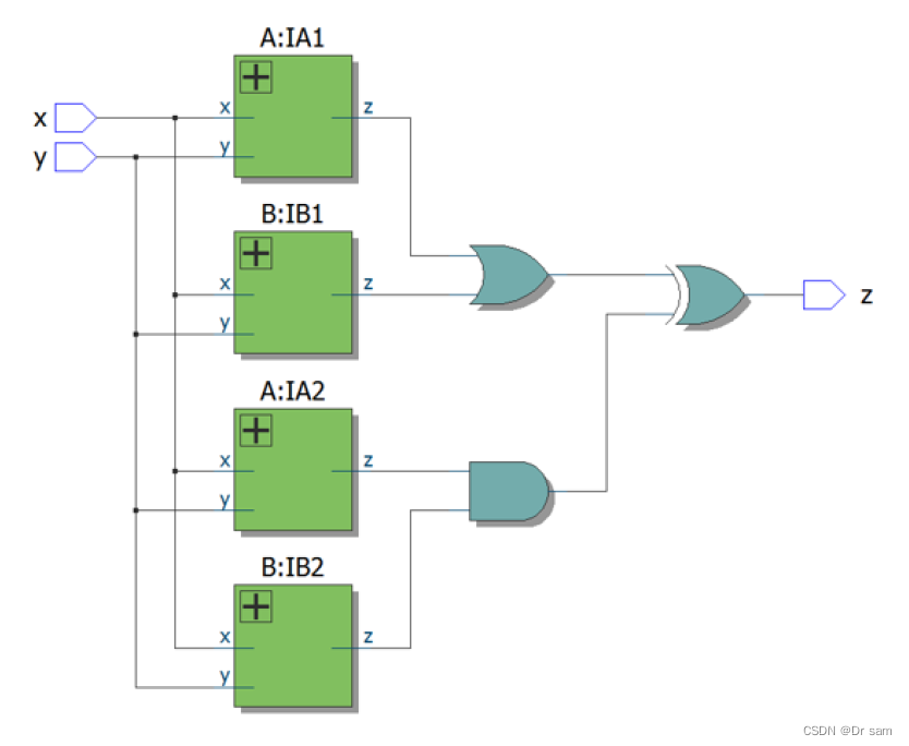
See mt2015_q4a and mt2015_q4b for the submodules used here. The top-level design consists of two instantiations each of subcircuits A and B, as shown below.
意思是说,该题的顶层设计由子电路 A 和 B 的两个实例组成,如下所示。其中实例A和B分别是前面两道题的设计。
我先贴上前面两个题目的代码:
mt2015_q4a
z = (x ^y) & x 把这个公式展开来化简一下;
module top_module (input x, input y, output z);
    and(z, x, ~y);
    // 或者 assign z = x & ~y ;
endmodule
mt2015_q4b
同样,根据时序图,x 和 y之间的关系是同或的关系
module top_module (input x, input y, output z);
    xnor(z, x, y);
    // 或者 assign z = ~(x ^ y);
endmodule
下面就是本题的最终结果了
mt2015_q4
我在top_module之外创建了两个子模块,分别对应上述的A和B;然后在top_module之中,分别实例化了4个子模块。对应图中4个绿色的部分。
然后再调用两个与门,和一个异或门,将结果传递给z。
用了o1, o2, o3, o4, o12, o34 这么几根线来记录中间数据,方便编程;
module top_module (input x, input y, output z);
    wire o1, o2, o3, o4, o12, o34;
    mod_a IA1(o1, x, y);
    mod_b IB1(o2, x, y);
    mod_a IA2(o3, x, y);
    mod_b IB2(o4, x, y);

    or(o12, o1, o2);
    and(o34, o3, o4);
    xor(z, o12, o34);
endmodule

module mod_a(output z, input x, input y);
    assign z = x & ~y ;
endmodule

module mod_b(output z, input x, input y);
    assign z = ~(x ^ y);
endmodule


 468
468


 被折叠的 条评论
为什么被折叠?
被折叠的 条评论
为什么被折叠?
 到【灌水乐园】发言


