


1.启动simulink
命令行输入simulink或者
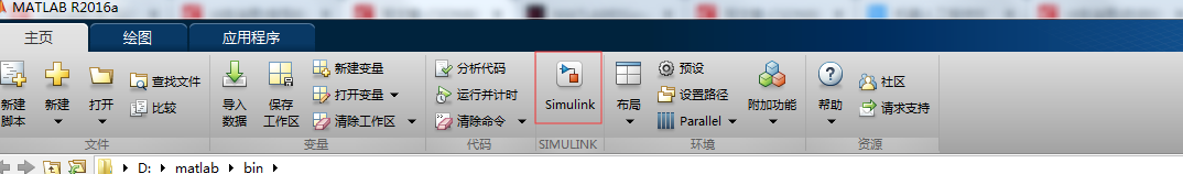
会弹出

2,点击blank model,出现新窗口

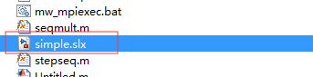
新建或者打开模型文件
There are two major classes of items in Simulink: blocks and lines. Blocks are used to generate, modify, combine, output, and display signals. Lines are used to transfer signals from one block to another.
There are several general classes of blocks within the Simulink library:
Sources: used to generate various signals
Sinks: used to output or display signals
Continuous: continuous-time system elements (transfer functions, state-space models, PID controllers, etc.)
Discrete: linear, discrete-time system elements (discrete transfer functions, discrete state-space models, etc.)
Math Operations: contains many common math operations (gain, sum, product, absolute value, etc.)
Ports & Subsystems: contains useful blocks to build a system
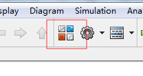

RUN
添加block,修改transfer function

run

继续修改transfer function
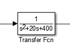

Since the new transfer function has a very fast response, it compressed into a very narrow part of the scope window. This is not really a problem with the scope, but with the simulation itself. Simulink simulated the system for a full ten seconds even though the system had reached steady state shortly after one second.
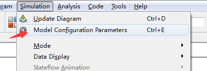
To correct this, you need to change the parameters of the simulation itself. In the model window, select Model Configuration Parameters from the Simulation menu. You will see the following dialog box.

There are many simulation parameter options; we will only be concerned with the start and stop times, which tell Simulink over what time period to perform the simulation. Change Start time from 0.0 to 0.8 (since the step doesn’t occur until t = 1.0). Change Stop time from 10.0 to 2.0, which should be only shortly after the system settles. Close the dialog box and rerun the simulation. Now, the scope window should provide a much better display of the step response as shown below.


Building Systems
First, you will gather all of the necessary blocks from the block libraries. Then you will modify the blocks so they correspond to the blocks in the desired model. Finally, you will connect the blocks with lines to form the complete system. After this, you will simulate the complete system to verify that it works.
Gathering Blocks
Follow the steps below to collect the necessary blocks:
Create a new model (New from the File menu or hit Ctrl-N). You will get a blank model window.
Click on the Tools tab and then select Library Browser.
Then click on the Sources listing in the Simulink library browser.

This will bring up the Sources block library. Sources are used to generate signals.
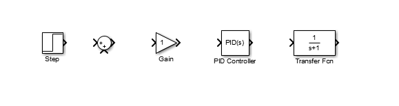
Drag the Step block from the Sources window into the left side of your model window.

Click on the Math Operations listing in the main Simulink window.
From this library, drag a Sum and Gain block into the model window and place them to the right of the Step block in that order.
Click on the Continuous listing in the main Simulink window.
First, from this library, drag a PID Controller block into the model window and place it to the right of the Gain block.
From the same library, drag a Transfer Function block into the model window and place it to the right of the PID Controller block.


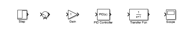
Click on the Sinks listing in the main Simulink window.
Drag the Scope block into the right side of the model window.
Modify Blocks
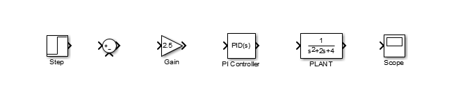
Double-click on the Sum block. Since you will want the second input to be subtracted, enter ± into the list of signs field. Close the dialog box.
Double-click the Gain block. Change the gain to 2.5 and close the dialog box.
Double-click the PID Controller block and change the Proportional gain to 1 and the Integral gain to 2. Close the dialog box.
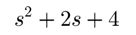
Double-click the Transfer Function block. Leave the numerator [1], but change the denominator to [1 2 4]. Close the dialog box. The model should appear as:
Change the name of the PID Controller block to PI Controller by double-clicking on the word PID Controller.
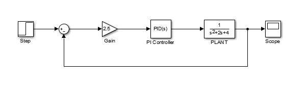
Similarly, change the name of the Transfer Function block to Plant. Now, all the blocks are entered properly. Your model should appear as:
Drag the mouse from the output terminal of the Step block to the positive input of the Sum input. Another option is to click on the Step block and then Ctrl-Click on the Sum block to connect the two togther. You should see the following.
Drag a line off the negative portion of the Sum block straight down and release the mouse so the line is incomplete. From the endpoint of this line, click and drag to the line between the Plant and the Scope. The model should now appear as follows.
以上照做后可能会报错
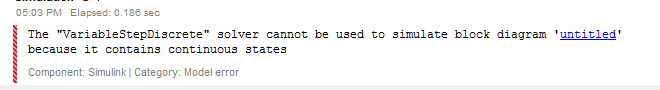
解决方法就是

解决

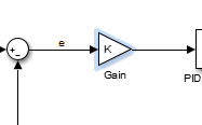
参数可以用代数代替
In some cases, parameters, such as gain, may be calculated in MATLAB to be used in a Simulink model. If this is the case, it is not necessary to enter the result of the MATLAB calculation directly into Simulink. For example, suppose we calculated the gain in MATLAB in the variable K. Emulate this by entering the following command at the MATLAB command prompt.
也可以run


 2477
2477


 被折叠的 条评论
为什么被折叠?
被折叠的 条评论
为什么被折叠?
 到【灌水乐园】发言


