


简介
在正点原子例程中
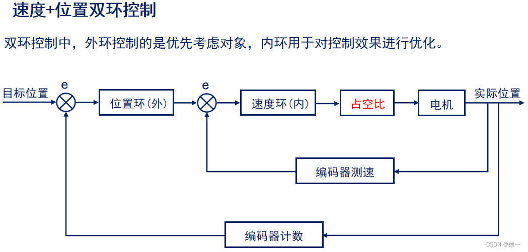
比如这里考虑目标位置为对象,main函数中注意看最后两行代码
int main(void)
{
    uint8_t key;
    uint16_t t;
    uint8_t debug_cmd = 0;

    HAL_Init();                                 /* 初始化HAL库 */
    sys_stm32_clock_init(85, 2, 2, 4, 8);       /* 设置时钟,170Mhz */
    delay_init(170);                            /* 延时初始化 */
    usart_init(115200);                         /* 串口初始化为115200 */
    led_init();                                 /* 初始化LED */
    lcd_init();                                 /* 初始化LCD */
    key_init();                                 /* 初始化按键 */
    pid_init();                                 /* 初始化PID参数 */
    atim_timx_cplm_pwm_init(8500 - 1, 0);       /* 170 000 000 / 1 = 170 000 000 170Mhz的计数频率,计数8500次为50us */
    dcmotor_init();                             /* 初始化电机 */
    gtim_timx_encoder_chy_init(0XFFFF - 1, 0);  /* 编码器定时器初始化,不分频 */
    btim_timx_int_init(1000 - 1 , 170 - 1);     /* 基本定时器初始化,1ms计数周期 */

#if DEBUG_ENABLE                                /* 开启调试 */

    debug_init();                               /* 初始化调试 */
    debug_send_motorcode(DC_MOTOR);             /* 上传电机类型(直流有刷电机) */
    debug_send_motorstate(IDLE_STATE);          /* 上传电机状态(空闲) */

    /* 同步数据PID参数到上位机 ,无论同步哪一组数据,目标值地址只能是外环PID的 */
    debug_send_initdata(TYPE_PID1, (float *)(&g_location_pid.SetPoint), L_KP, L_KI, L_KD);  /* 位置环PID参数(PID1)*/
    debug_send_initdata(TYPE_PID2, (float *)(&g_location_pid.SetPoint), S_KP, S_KI, S_KD);  /* 速度环PID参数(PID2)*/
可以看到,这里的双环pid设置的目标值都是位置目标值,都是外环pid的,只是内外环的pid三个系数不同。
代码配置
配置步骤
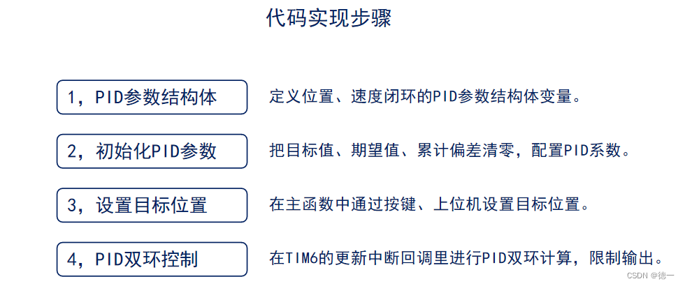
定义结构体代码+配置PID系数
#include "./BSP/PID/pid.h"
#include "./BSP/DC_MOTOR/dc_motor.h"

PID_TypeDef  g_location_pid;             /* 位置环PID参数结构体 */
PID_TypeDef  g_speed_pid;                /* 速度环PID参数结构体 */

/**
 * @brief       pid初始化
 * @param       无
 * @retval      无
 */
void pid_init(void)
{
    /* 初始化位置环PID参数 */
    g_location_pid.SetPoint = 0.0;       /* 目标值 */
    g_location_pid.ActualValue = 0.0;    /* 期望输出值 */
    g_location_pid.SumError = 0.0;       /* 积分值 */
    g_location_pid.Error = 0.0;          /* Error[1] */
    g_location_pid.LastError = 0.0;      /* Error[-1] */
    g_location_pid.PrevError = 0.0;      /* Error[-2] */
    g_location_pid.Proportion = L_KP;    /* 比例常数 Proportional Const */
    g_location_pid.Integral = L_KI;      /* 积分常数 Integral Const */
    g_location_pid.Derivative = L_KD;    /* 微分常数 Derivative Const */

    /* 初始化速度环PID参数 */
    g_speed_pid.SetPoint = 0.0;          /* 目标值 */
    g_speed_pid.ActualValue = 0.0;       /* 期望输出值 */
    g_speed_pid.SumError = 0.0;          /* 积分值 */
    g_speed_pid.Error = 0.0;             /* Error[1] */
    g_speed_pid.LastError = 0.0;         /* Error[-1] */
    g_speed_pid.PrevError = 0.0;         /* Error[-2] */
    g_speed_pid.Proportion = S_KP;       /* 比例常数 Proportional Const */
    g_speed_pid.Integral = S_KI;         /* 积分常数 Integral Const */
    g_speed_pid.Derivative = S_KD;       /* 微分常数 Derivative Const */
}
main函数设置目标位置
以下是按键控制设置目标位置
key = key_scan(0);                                  /* 按键扫描 */
        if(key == KEY0_PRES)                                /* 当key0按下 */
        {
            g_run_flag = 1;                                 /* 标记电机启动 */
            dcmotor_start();                                /* 开启电机 */
            g_location_pid.SetPoint += 1320;                /* 正转一圈,电机旋转圈数 = 编码器总计数值 / 44 / 30 */

            if (g_location_pid.SetPoint >= 6600)            /* 限制电机位置(正转最大5圈) */
            {
                g_location_pid.SetPoint = 6600;
            }
#if DEBUG_ENABLE
            debug_send_motorstate(RUN_STATE);               /* 上传电机状态(运行) */
#endif
        }

        else if(key == KEY1_PRES)                           /* 当key1按下 */
        {
            g_run_flag = 1;                                 /* 标记电机启动 */
            dcmotor_start();                                /* 开启电机 */
            g_location_pid.SetPoint -= 1320;                /* 反转一圈 */

            if (g_location_pid.SetPoint <= -6600)           /* 限制电机位置(反转最大5圈) */
            {
                g_location_pid.SetPoint = -6600;
            }
#if DEBUG_ENABLE
            debug_send_motorstate(RUN_STATE);               /* 上传电机状态(运行) */
#endif
        }

        else if(key == KEY2_PRES)                           /* 当key2按下 */
        {
            g_location_pid.SetPoint = 0;                    /* 恢复初始位置 */
        }
以下是上位机控制设置目标位置
		/* 接收PID助手设置的位置环PID参数 */
        debug_receive_pid(TYPE_PID1, (float *)&g_location_pid.Proportion,(float *)&g_location_pid.Integral, (float *)&g_location_pid.Derivative);

        /* 接收PID助手设置的速度环PID参数 */
        debug_receive_pid(TYPE_PID2, (float *)&g_speed_pid.Proportion, (float *)&g_speed_pid.Integral, (float *)&g_speed_pid.Derivative);

        debug_set_point_range(6600, -6600, 6600);                       /* 设置目标调节范围 */

        debug_cmd = debug_receive_ctrl_code();                          /* 读取上位机指令 */

        if (debug_cmd == HALT_CODE)                                     /* 电机停机 */
        {
            g_location_pid.SetPoint = 0;                                /* 恢复初始位置 */
        }
        else if (debug_cmd == RUN_CODE)                                 /* 电机运行 */
        {
            g_run_flag = 1;                                             /* 标记电机启动 */
            dcmotor_start();                                            /* 开启电机 */
            g_location_pid.SetPoint = 1320;                             /* 设置目标位置 */
            debug_send_motorstate(RUN_STATE);                           /* 上传电机状态(运行) */
        }
回调函数的设置
/**
 * @brief       定时器更新中断回调函数
 * @param        htim:定时器句柄指针
 * @note        此函数会被定时器中断函数共同调用的
 * @retval      无
 */
void HAL_TIM_PeriodElapsedCallback(TIM_HandleTypeDef *htim)
{
    static uint8_t val = 0;

    if (htim->Instance == TIM3)											/*通用定时器3*/
    {
        if(__HAL_TIM_IS_TIM_COUNTING_DOWN(&g_timx_encode_chy_handle))   /* 判断CR1的DIR位,也就是正反转判断,以及 */
        {
            g_timx_encode_count--;                                      /* DIR位为1,也就是递减计数 */
        }
        else
        {
            g_timx_encode_count++;                                      /* DIR位为0,也就是递增计数 */
        }
    }
    else if (htim->Instance == BTIM_TIMX_INT)
    {
        int Encode_now = gtim_get_encode();                             /* 获取编码器值,用于计算速度 */

        speed_computer(Encode_now, 5);                                  /* 中位平均值滤除编码器抖动数据,5ms计算一次速度 */

        if (val % SMAPLSE_PID_SPEED == 0)                               /* 进行一次pid计算 */
        {
            if (g_run_flag)                                             /* 判断电机是否启动了 */
            {
                g_motor_data.location = (float)Encode_now;              /* 获取当前编码器总计数值,也就是电机参数结构体中位置的参数,用于位置闭环控制 */

                g_motor_data.motor_pwm = increment_pid_ctrl(&g_location_pid, g_motor_data.location);    /* 位置环PID控制(外环),increment_pid_ctrl这个函数返回的是实际的输出值 */

                if (g_motor_data.motor_pwm >= 150)                      /* 限制外环输出(目标速度) */
                {
                    g_motor_data.motor_pwm = 150;
                }
                else if (g_motor_data.motor_pwm <= -150)
                {
                    g_motor_data.motor_pwm = -150;
                }

                g_speed_pid.SetPoint = g_motor_data.motor_pwm;          /* 设置目标速度,外环输出作为内环输入,g_speed_pid.SetPoint是作为内环的速度环,这里给它设置目标值为外环的输出 */

                g_motor_data.motor_pwm = increment_pid_ctrl(&g_speed_pid, g_motor_data.speed);          /* 速度环PID控制(内环) */

                if (g_motor_data.motor_pwm >= 8200)                     /* 限制占空比 */
                {
                    g_motor_data.motor_pwm = 8200;
                }
                else if (g_motor_data.motor_pwm <= -8200)
                {
                    g_motor_data.motor_pwm = -8200;
                }

#if DEBUG_ENABLE  /* 发送基本参数*/

                debug_send_wave_data( 1 ,g_motor_data.location);                                        /* 选择通道1,发送实际位置(波形显示)*/
                debug_send_wave_data( 2 ,g_location_pid.SetPoint);                                      /* 选择通道2,发送目标位置(波形显示)*/
#endif
                motor_pwm_set(g_motor_data.motor_pwm);                                                  /* 设置占空比(电机转速) */
            }
            val = 0;
        }
        val ++;
    }
}
在回调函数中会计算出与实际的输出值,来调节pwm的占空比
三环控制,引入电流环
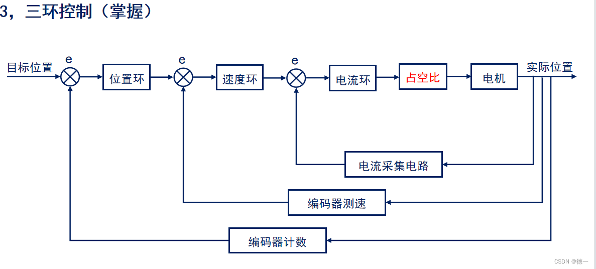
可以看到电流环是加在最里的,同时三环的反馈方式都是不同的,位置环是通过编码器的计数,速度环是编码器根据计数值再计算得出的速度值,最内环是电流采集电路,利用adc采样再次调整输出,通过调整占空比的方式。


 8622
8622

 被折叠的 条评论
为什么被折叠?
被折叠的 条评论
为什么被折叠?
 到【灌水乐园】发言


