


Shift4
Build a 4-bit shift register (right shift), with asynchronous reset, synchronous load, and enable.
- areset: Resets shift register to zero.
- load: Loads shift register with data[3:0] instead of shifting.
- ena: Shift right (q[3] becomes zero, q[0] is shifted out and disappears).
- q: The contents of the shift register.
If both the load and ena inputs are asserted (1), the load input has higher priority.
module top_module(
    input clk,
    input areset,  // async active-high reset to zero
    input load,
    input ena,
    input [3:0] data,
    output reg [3:0] q);
    always @(posedge clk, posedge areset) begin
        if(areset) q <= 0;
        else if(load) q <= data;
        else if(ena) q <= (q >> 1);
    end
endmodule
/* way 2:
module top_module(
	input clk,
	input areset,
	input load,
	input ena,
	input [3:0] data,
	output reg [3:0] q);

	// Asynchronous reset: Notice the sensitivity list.
	// The shift register has four modes:
	//   reset
	//   load
	//   enable shift
	//   idle -- preserve q (i.e., DFFs)
	always @(posedge clk, posedge areset) begin
		if (areset)		// reset
			q <= 0;
		else if (load)	// load
			q <= data;
		else if (ena)	// shift is enabled
			q <= q[3:1];	// Use vector part select to express a shift.
	end

endmodule
*/
Rotate100
Build a 100-bit left/right rotator, with synchronous load and left/right enable. A rotator shifts-in the shifted-out bit from the other end of the register, unlike a shifter that discards the shifted-out bit and shifts in a zero. If enabled, a rotator rotates the bits around and does not modify/discard them.
- load: Loads shift register with data[99:0] instead of rotating.
- ena[1:0]: Chooses whether and which direction to rotate.
- 2'b01 rotates right by one bit
- 2'b10 rotates left by one bit
- 2'b00 and 2'b11 do not rotate.
- q: The contents of the rotator.
module top_module(
    input clk,
    input load,
    input [1:0] ena,
    input [99:0] data,
    output reg [99:0] q);
    always @(posedge clk) begin
        if(load) q <= data;
        else if (ena == 2'd01) q <= {q[0], q[99:1]};
        else if (ena == 2'd10) q <= {q[98:0], q[99]};
        else q <= q;
    end
endmodule
Shift18
Build a 64-bit arithmetic shift register, with synchronous load. The shifter can shift both left and right, and by 1 or 8 bit positions, selected by amount.
An arithmetic right shift shifts in the sign bit of the number in the shift register (q[63] in this case) instead of zero as done by a logical right shift. Another way of thinking about an arithmetic right shift is that it assumes the number being shifted is signed and preserves the sign, so that arithmetic right shift divides a signed number by a power of two.
There is no difference between logical and arithmetic left shifts.
- load: Loads shift register with data[63:0] instead of shifting.
- ena: Chooses whether to shift.
- amount: Chooses which direction and how much to shift.
- 2'b00: shift left by 1 bit.
- 2'b01: shift left by 8 bits.
- 2'b10: shift right by 1 bit.
- 2'b11: shift right by 8 bits.
- q: The contents of the shifter.
module top_module(
    input clk,
    input load,
    input ena,
    input [1:0] amount,
    input [63:0] data,
    output reg [63:0] q);
    always @(posedge clk) begin
        if(load) q <= data;
        else if(ena) begin
            case(amount)
                2'd0: q <= (q << 1);
                2'd1: q <= (q << 8);
                2'd2: q <= {q[63], q[63:1]};
                2'd3: q <= {{8{q[63]}}, q[63:8]};
            endcase
        end
    end
endmodule 
 Lfsr5
Lfsr5
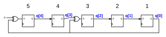
module top_module(
    input clk,
    input reset,    // Active-high synchronous reset to 5'h1
    output [4:0] q
);
    always @(posedge clk)begin
        if(reset) q <= 5'h1;
        else begin
            q[0] <= q[1];
            q[1] <= q[2];
            q[2] <= q[3] ^ q[0];
            q[3] <= q[4];
            q[4] <= q[0] ^ 0;
        end
    end
endmodule

Mt2015 lfsr

module top_module (
	input [2:0] SW,      // R
	input [1:0] KEY,     // L and clk
	output [2:0] LEDR);  // Q
    reg [2:0]LEDR_next;
    always @(*) begin
        LEDR_next[1] = LEDR[0];
        LEDR_next[2] = LEDR[2] ^ LEDR[1];
        LEDR_next[0] = LEDR[2];
    end

    always @(posedge KEY[0])begin
        if(KEY[1]) LEDR <= SW;
        else LEDR <= LEDR_next;
    end
endmodule
Lfsr32
Build a 32-bit Galois LFSR with taps at bit positions 32, 22, 2, and 1.
module top_module(
    input clk,
    input reset,    // Active-high synchronous reset to 32'h1
    output [31:0] q
);
    reg [31:0] q_next;
    always @(*) begin
        q_next = q[31:1];
        q_next[0] = q[0] ^ q[1];
        q_next[1] = q[0] ^ q[2];
        q_next[21] = q[0] ^ q[22];
        q_next[31] = q[0];
    end

    always @(posedge clk)begin
        if(reset) q <= 32'h1;
        else q <= q_next;
    end
endmodule
Exams/m2014 q4k
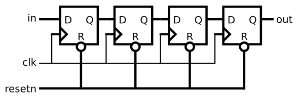
module top_module (
    input clk,
    input resetn,   // synchronous reset
    input in,
    output out);
    reg[3:0] d;
    always @(posedge clk)begin
        if(!resetn) d <= 4'h0;
        else d <= {d[2:0],in};
    end

    assign out = d[3];
endmodule
Exams/2014 q4b

- Connect the R inputs to the SW switches,
- clk to KEY[0],
- E to KEY[1],
- L to KEY[2], and
- w to KEY[3].
- Connect the outputs to the red lights LEDR[3:0].
module top_module (
    input [3:0] SW,
    input [3:0] KEY,
    output [3:0] LEDR
); //
	MUXDFF MUXDFF_1(
        .clk(KEY[0]),
        .w(KEY[3]),
        .R(SW[3]),
        .E(KEY[1]),
        .L(KEY[2]),
        .Q(LEDR[3])
    );
    MUXDFF MUXDFF_2(
        .clk(KEY[0]),
        .w(LEDR[3]),
        .R(SW[2]),
        .E(KEY[1]),
        .L(KEY[2]),
        .Q(LEDR[2])
    );
    MUXDFF MUXDFF_3(
        .clk(KEY[0]),
        .w(LEDR[2]),
        .R(SW[1]),
        .E(KEY[1]),
        .L(KEY[2]),
        .Q(LEDR[1])
    );
    MUXDFF MUXDFF_4(
        .clk(KEY[0]),
        .w(LEDR[1]),
        .R(SW[0]),
        .E(KEY[1]),
        .L(KEY[2]),
        .Q(LEDR[0])
    );
endmodule

module MUXDFF (
    input clk,
    input w, R, E, L,
    output Q
);
	always@(posedge clk)begin
        if(L)begin
            Q <= R;
        end
        else begin
            if(E)begin
                Q <= w;
            end
            else begin
                Q <= Q;
            end
        end
    end
endmodule
Exams/ece241 2013 q12
n this question, you will design a circuit for an 8x1 memory, where writing to the memory is accomplished by shifting-in bits, and reading is "random access", as in a typical RAM. You will then use the circuit to realize a 3-input logic function.
First, create an 8-bit shift register with 8 D-type flip-flops. Label the flip-flop outputs from Q[0]...Q[7]. The shift register input should be called S, which feeds the input of Q[0] (MSB is shifted in first). The enable input controls whether to shift. Then, extend the circuit to have 3 additional inputs A,B,C and an output Z. The circuit's behaviour should be as follows: when ABC is 000, Z=Q[0], when ABC is 001, Z=Q[1], and so on. Your circuit should contain ONLY the 8-bit shift register, and multiplexers. (Aside: this circuit is called a 3-input look-up-table (LUT)).
module top_module (
    input clk,
    input enable,
    input S,
    input A, B, C,
    output Z );
    reg [0:7] q;
    always @(posedge clk) begin
        if(enable) q <= {S, q[0:6]};
        else q <= q;
    end

    assign Z = q[{A,B,C}];
endmodule


 390
390


 被折叠的 条评论
为什么被折叠?
被折叠的 条评论
为什么被折叠?
 到【灌水乐园】发言


