


1.发展
8B/10B编码是1983年由IBM公司的Al Widmer和PeterFranaszek所提出的数据传输编码标准,目前已经被广泛应用到高速串行总线,如IEEE1394b、SATA、PCI-Express、Infini-band、FiberChannel、XAUI、RapidIO、USB 3.0的美好。8B/10B编码将待发送的8位数据转换成10位代码组,其目的是保证直流平衡,以及足够密集的电平转换。
2.用途
在高速系统中,连续的0(低电平)或者1(高电平)并不稳定极容易导致误读。

在光通信中线路码的功率谱密度中的低频分量是由码流中的“0”、“1” 分布状态来决定的, 低频分量小, 说明“0”、 “1”分布比较均匀, 直流电平比较恒定, 也就是信号基线浮动小, 有利于接收端判决电路的正常工作。为了于减少码流的基线漂移, 即要求码流中的“1"、 "0” 码分布均匀, 否则不利于接收端的的再生判决。
3.具体原理描述
8B10B 编码方法是把8bit代码组合编码成10bit代码,代码组合包含256个数据字符编码和 12 个控制字符编码,分别记为Dx. y和Kx.y。通过仔细选择编码方法可以获得不同的优化特性。这些特性包括满足串行/解串行器功能必须的变换; 确保“0” 码元与“1” 码元个数的一致, 又称为直流均衡; 确保字节同步易于实现(在一个比特流中找到字节的起始位); 以及对误码率有足够的容忍能力和降低设计复杂度。
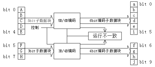
8B10B 编码方案是把8bit数据分成2个子分组: 3个最高有效位(y)和5个最 低有效位( x)。代码字按顺序排列,从最高有效位到最低有效位分别记为H、G、F和E、D、C、B、A。3bit 的子分组编码成4 bit,记为j、h、g、f; 5bit的子分组编码成6bit,记为i、e、d、c、b、a,其映射关系如图2.2.1所示,4bit 和 6bit 的子分组再组合成 10bit 的编码值。
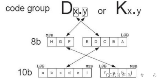
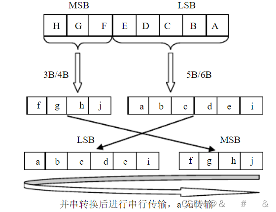
图2.2.1
编码时,低5bit原数据EDCBA经过5B6B编码成为6bit码abcdei,高3bit原数据HGF经3B4B成为4bit码fghj,最后再将两部分组合起来形成一个10bit码abcdeifghj。10B码在发送时,按照先发送低位在发送高位的顺序发送,如图2.2.2。
如图2.2.2
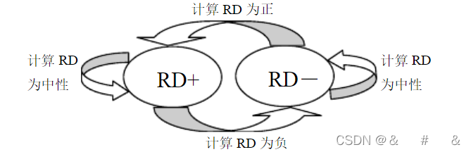
在编码过程中,用一个极性偏差( running disparity,RD)参数表示不平衡度,在不平衡时用 2 个 10 bit 字符表示一个 8 位字符,其中一个称为 RD- ,表示“1” 的个数比“0” 的个数多 2 个,另一个称为 RD+ ,表示“0” 的个数比“1” 的个数多 2 个。 这种不平衡差值为 2 的数需要采用 2 个 10bit 表示 1 个 8bit,主要用于 K 码的控制字符。RD取值图规则如图2.2.3:
| Rules for Running Disparity | ||
| Previous RD | Disparity of 6 or 4 Bit Code | Next RD |
| -1 | -2 | not used (choose +2 encoding instead) |
| -1 | 0 | -1 |
| -1 | +2 | +1 |
| +1 | -2 | -1 |
| +1 | 0 | +1 |
| +1 | +2 | not used (choose -2 encoding instead) |
图2.2.3
4.代码实现
编码部分
//=======8B10B编码
//=======输入时钟,输入数据、输出数据
//=======输入数据8B,最高位为指示位,1表示命令,0表示数据
//=======datain={ihgf,edcba},dataout={jhgf,iedcba}
//
module encode_8b10b (
  input       sys_clk,  //与数据时钟同步
  input       rst_n,
  input [8:0] datain,
  output[9:0] dataout,
 );

reg  dispin;  //输入RD,0:RD-,1:RD+
wire aeqb;
wire ceqd;
wire l22;
wire l40;
wire l04;
wire l13;
wire l31;
wire k28;
wire D16_18;
wire pd1s6;  // pds16 indicates cases where d-1 is assumed + to get our encoded value
wire nd1s6;  // nds16 indicates cases where d-1 is assumed - to get our encoded value
wire ndos6;  // ndos6 is pds16 cases where d-1 is + yields - disp out - all of them
wire pdos6;  // pdos6 is nds16 cases where d-1 is - yields + disp out - all but one
// some Dx.7 and all Kx.7 cases result in run length of 5 case unless
// an alternate coding is used (referred to as Dx.A7, normal is Dx.P7)
// specifically, D11, D13, D14, D17, D18, D19.
wire alt7;
wire nd1s4;   // nd1s4 is cases where d-1 is assumed - to get our encoded value
wire pd1s4;   // pd1s4 is cases where d-1 is assumed + to get our encoded value
wire ndos4;   // ndos4 is pd1s4 cases where d-1 is + yields - disp out - just some
wire pdos4;   // pdos4 is nd1s4 cases where d-1 is - yields + disp out
wire disp6;   //
wire compls4;
wire compls6;

always@(posedge sys_clk or negedge rst_n)
begin
   if(!rst_n)
     dispin <= 1'b0;
   else
     dispin <= dispout;
 end

assign aeqb = (datain[0] & datain[1]) | (!datain[0] & !datain[1]) ;
assign ceqd = (datain[2] & datain[3]) | (!datain[2] & !datain[3]) ;
assign l22 = (datain[0] & datain[1] & !datain[2] & !datain[3]) | (datain[2] & datain[3] & !datain[1] & !datain[1]) | (!aeqb & !ceqd) ;
assign l40 = datain[0] & datain[1] & datain[2] & datain[3] ;
assign l04 = !datain[0] & !datain[1] & !datain[2] & !datain[3] ;
assign l13 = (!aeqb & !datain[2] & !datain[3]) | (!ceqd & !datain[0] & !datain[1]) ;
assign l31 = (!aeqb & datain[2] & datain[3]) | ( !ceqd & datain[0] & datain[1]) ;
assign k28 = (datain[8] & datain[4] & datain[3] & datain[2] & !datain[1] & !datain[0]);
assign D16_18= (l22 & !datain[4]) | (datain[4] & !datain[3] & !datain[2] & !(datain[0]&datain[1]));
assign pd1s6 = (datain[4] & datain[3] & !datain[2] & !datain[1] & !datain[0]) | (!datain[4] & !l22 & !l31);
assign nd1s6 = datain[8] | (datain[4] & !l22 & !l13) | (!datain[4] & !datain[3] & datain[2] & datain[1] & datain[0]) ;
assign ndos6 = pd1s6 ;
assign pdos6 = datain[8] | (datain[4] & !l22 & !l13) ;
assign alt7 = datain[5] & datain[6] & datain[7] & (datain[8] | (dispin ? (!datain[4] & datain[3] & l31) : (datain[4] & !datain[3] & l13))) ;
assign nd1s4 = datain[5] & datain[6] ;
assign pd1s4 = (!datain[5] & !datain[6]) | (datain[8] & ((datain[5] & !datain[6]) | (!datain[5] & datain[6]))) ;
assign ndos4 = (!datain[5] & !datain[6]);
assign pdos4 = datain[5] & datain[6] & datain[7];

assign disp6 = dispin ^ (ndos6 | pdos6);
assign dispout = disp6 ^ (ndos4 | pdos4) ;

assign compls4 = (pd1s4 & !disp6) | (nd1s4 & disp6) ;
// now determine whether to do the complementing
  // complement if prev disp is - and pd1s6 is set, or + and nd1s6 is set
assign  compls6 = (pd1s6 & !dispin) | (nd1s6 & dispin) ;

// disparity out of 5b6b is disp in with pdso6 and ndso6
// pds16 indicates cases where d-1 is assumed + to get our encoded value
// ndos6 is cases where d-1 is + yields - disp out
// nds16 indicates cases where d-1 is assumed - to get our encoded value
// pdos6 is cases where d-1 is - yields + disp out
// disp toggles in all ndis16 cases, and all but that 1 nds16 case

// The 5B/6B encoding
assign dataout[0] = datain[0] ^ compls6;
assign dataout[1] =((datain[1] & !l40) | l04 ) ^ compls6;
assign dataout[2] =(l04 | datain[2] | (datain[4] & datain[3] & !datain[2] & !datain[1] & !datain[0]))^ compls6;
assign dataout[3] =(datain[3] & ! (datain[0] & datain[1] & datain[2]))^ compls6;
assign dataout[4] =((datain[4] | l13) & !(datain[4] & datain[3] & !datain[2] & !datain[1] & !datain[0]))^ compls6;
assign dataout[5] =(D16_18 | (datain[4] & l40) | k28 |(datain[4] & !datain[3] & datain[2] & !datain[1] & !datain[0]))^ compls6;

assign dataout[6] =( datain[5] & ! alt7)^ compls4;
assign dataout[7] =(datain[6] | (!datain[5] & !datain[6] & !datain[7]))^ compls4;
assign dataout[8] = datain[7] ^ compls4;
assign dataout[9] = ((!datain[7] & (datain[6] ^ datain[5])) | alt7) ^ compls4;

 endmodule
5.参考资料
维基百科中有较为详细的描述,为方便查阅复制在下面了
In telecommunications, 8b/10b is a line code that maps 8-bit words to 10-bit symbols to achieve DC balance and bounded disparity, and at the same time provide enough state changes to allow reasonable clock recovery. This means that the difference between the counts of ones and zeros in a string of at least 20 bits is no more than two, and that there are not more than five ones or zeros in a row. This helps to reduce the demand for the lower bandwidth limit of the channel necessary to transfer the signal.[1]
In telecommunications, 8b/10b is a line code that maps 8-bit words to 10-bit symbols to achieve DC balance and bounded disparity, and at the same time provide enough state changes to allow reasonable clock recovery. This means that the difference between the counts of ones and zeros in a string of at least 20 bits is no more than two, and that there are not more than five ones or zeros in a row. This helps to reduce the demand for the lower bandwidth limit of the channel necessary to transfer the signal.[1]
An 8b/10b code can be implemented in various ways, where the design may focus on specific parameters such as hardware requirements, DC-balance, etc. One implementation was designed by K. Odaka for the DAT digital audio recorder.[2] Kees Schouhamer Immink designed an 8b/10b code for the DCC audio recorder.[3] The IBM implementation was described in 1983 by Al Widmer and Peter Franaszek.[4][5]
IBM implementation
As the scheme name suggests, eight bits of data are transmitted as a 10-bit entity called a symbol, or character. The low five bits of data are encoded into a 6-bit group (the 5b/6b portion) and the top three bits are encoded into a 4-bit group (the 3b/4b portion). These code groups are concatenated together to form the 10-bit symbol that is transmitted on the wire. The data symbols are often referred to as D.x.y where x ranges over 0–31 and y over 0–7. Standards using the 8b/10b encoding also define up to 12 special symbols (or control characters) that can be sent in place of a data symbol. They are often used to indicate start-of-frame, end-of-frame, link idle, skip and similar link-level conditions. At least one of them (i.e. a "comma" symbol) needs to be used to define the alignment of the 10-bit symbols. They are referred to as K.x.y and have different encodings from any of the D.x.y symbols.
Because 8b/10b encoding uses 10-bit symbols to encode 8-bit words, some of the possible 1024 (10 bit, 210) symbols can be excluded to grant a run-length limit of 5 consecutive equal bits and to ensure the difference between the count of zeros and ones to be no more than two. Some of the 256 possible 8-bit words can be encoded in two different ways. Using these alternative encodings, the scheme is able to achieve long-term DC-balance in the serial data stream. This permits the data stream to be transmitted through a channel with a high-pass characteristic, for example Ethernet's transformer-coupled unshielded twisted pair or optical receivers using automatic gain control.
Encoding tables
Note that in the following tables, for each input byte, A is the least significant bit, and H the most significant. The output gains two extra bits, i and j. The bits are sent low to high: a, b, c, d, e, i, f, g, h, and j; i.e., the 5b/6b code followed by the 3b/4b code. This ensures the uniqueness of the special bit sequence in the comma symbols.
The residual effect on the stream to the number of zero and one bits transmitted is maintained as the running disparity (RD) and the effect of slew is balanced by the choice of encoding for following symbols.
The 5b/6b code is a paired disparity code, and so is the 3b/4b code. Each 6- or 4-bit code word has either equal numbers of zeros and ones (a disparity of zero), or comes in a pair of forms, one with two more zeros than ones (four zeros and two ones, or three zeros and one one, respectively) and one with two less. When a 6- or 4-bit code is used that has a non-zero disparity (count of ones minus count of zeros; i.e., −2 or +2), the choice of positive or negative disparity encodings must be the one that toggles the running disparity. In other words, the non zero disparity codes alternate.
Running disparity[edit]
8b/10b coding is DC-free, meaning that the long-term ratio of ones and zeros transmitted is exactly 50%. To achieve this, the difference between the number of ones transmitted and the number of zeros transmitted is always limited to ±2, and at the end of each symbol, it is either +1 or −1. This difference is known as the running disparity (RD).
This scheme needs only two states for the running disparity of +1 and −1. It starts at −1.[6]
For each 5b/6b and 3b/4b code with an unequal number of ones and zeros, there are two bit patterns that can be used to transmit it: one with two more "1" bits, and one with all bits inverted and thus two more zeros. Depending on the current running disparity of the signal, the encoding engine selects which of the two possible six- or four-bit sequences to send for the given data. Obviously, if the six-bit or four-bit code has equal numbers of ones and zeros, there is no choice to make, as the disparity would be unchanged, with the exceptions of sub-blocks D.07 (00111) and D.x.3 (011). In either case the disparity is still unchanged, but if RD is positive when D.07 is encountered 000111 is used, and if it is negative 111000 is used. Likewise, if RD is positive when D.x.3 is encountered 0011 is used, and if it is negative 1100 is used. This is accurately reflected in the charts below, but is worth making additional mention of as these are the only two sub-blocks with equal numbers of 1s and 0s that each have two possible encodings.
| previous RD | Disparity of code word | Disparity chosen | next RD |
|---|---|---|---|
| −1 | 0 | 0 | −1 |
| −1 | ±2 | +2 | +1 |
| +1 | 0 | 0 | +1 |
| +1 | ±2 | −2 | −1 |
5b/6b code (abcdei)[edit]
| Input | RD = −1 | RD = +1 | Input | RD = −1 | RD = +1 | ||||
|---|---|---|---|---|---|---|---|---|---|
| Code | EDCBA | a b c d e i | Code | EDCBA | a b c d e i | ||||
| D.00 | 00000 | 100111 | 011000 | D.16 | 10000 | 011011 | 100100 | ||
| D.01 | 00001 | 011101 | 100010 | D.17 | 10001 | 100011 | |||
| D.02 | 00010 | 101101 | 010010 | D.18 | 10010 | 010011 | |||
| D.03 | 00011 | 110001 | D.19 | 10011 | 110010 | ||||
| D.04 | 00100 | 110101 | 001010 | D.20 | 10100 | 001011 | |||
| D.05 | 00101 | 101001 | D.21 | 10101 | 101010 | ||||
| D.06 | 00110 | 011001 | D.22 | 10110 | 011010 | ||||
| D.07 | 00111 | 111000 | 000111 | D.23 † | 10111 | 111010 | 000101 | also used for the K.23.7 symbol | |
| D.08 | 01000 | 111001 | 000110 | D.24 | 11000 | 110011 | 001100 | ||
| D.09 | 01001 | 100101 | D.25 | 11001 | 100110 | ||||
| D.10 | 01010 | 010101 | D.26 | 11010 | 010110 | ||||
| D.11 | 01011 | 110100 | D.27 † | 11011 | 110110 | 001001 | also used for the K.27.7 symbol | ||
| D.12 | 01100 | 001101 | D.28 | 11100 | 001110 | ||||
| D.13 | 01101 | 101100 | D.29 † | 11101 | 101110 | 010001 | also used for the K.29.7 symbol | ||
| D.14 | 01110 | 011100 | D.30 † | 11110 | 011110 | 100001 | also used for the K.30.7 symbol | ||
| D.15 | 01111 | 010111 | 101000 | D.31 | 11111 | 101011 | 010100 | ||
| not used | 111100 | 000011 | K.28 ‡ | 11100 | 001111 | 110000 | exclusively used for K.28.x symbols | ||
† also used for the 5b/6b code of K.x.7
‡ exclusively used for the 5b/6b code of K.28.y
3b/4b code (fghj)[edit]
| Input | RD = −1 | RD = +1 | Input | RD = −1 | RD = +1 | |||
|---|---|---|---|---|---|---|---|---|
| Code | HGF | f g h j | Code | HGF | f g h j | |||
| D.x.0 | 000 | 1011 | 0100 | K.x.0 | 000 | 1011 | 0100 | |
| D.x.1 | 001 | 1001 | K.x.1 ‡ | 001 | 0110 | 1001 | ||
| D.x.2 | 010 | 0101 | K.x.2 | 010 | 1010 | 0101 | ||
| D.x.3 | 011 | 1100 | 0011 | K.x.3 | 011 | 1100 | 0011 | |
| D.x.4 | 100 | 1101 | 0010 | K.x.4 | 100 | 1101 | 0010 | |
| D.x.5 | 101 | 1010 | K.x.5 ‡ | 101 | 0101 | 1010 | ||
| D.x.6 | 110 | 0110 | K.x.6 | 110 | 1001 | 0110 | ||
| D.x.P7 † | 111 | 1110 | 0001 | K.x.7 ‡ | 111 | 0111 | 1000 | |
| D.x.A7 † | 0111 | 1000 | ||||||
† For D.x.7, either the Primary (D.x.P7), or the Alternate (D.x.A7) encoding must be selected in order to avoid a run of five consecutive 0s or 1s when combined with the preceding 5b/6b code.
Sequences of exactly five identical bits are used in comma symbols for synchronization issues.
D.x.A7 is used only
- when RD = −1: for x = 17, 18 and 20 and
- when RD = +1: for x = 11, 13 and 14.
With x = 23, x = 27, x = 29, and x = 30, the 3b/4b code portion used for control symbols K.x.7 is the same as that for D.x.A7.
Any other D.x.A7 code can't be used as it would result in chances for misaligned comma sequences.
‡ Only K.28.1, K.28.5, and K.28.7 generate comma symbols, that contain a bit sequence of five 0s or 1s.
The symbol has the format 110000 01xx or 001111 10xx.
Control symbols[edit]
The control symbols within 8b/10b are 10b symbols that are valid sequences of bits (no more than six 1s or 0s) but do not have a corresponding 8b data byte. They are used for low-level control functions. For instance, in Fibre Channel, K28.5 is used at the beginning of four-byte sequences (called "Ordered Sets") that perform functions such as Loop Arbitration, Fill Words, Link Resets, etc.
Resulting from the 5b/6b and 3b/4b tables the following 12 control symbols are allowed to be sent:
| Input | RD = −1 | RD = +1 | |||
|---|---|---|---|---|---|
| Symbol | DEC | HEX | HGF EDCBA | abcdei fghj | abcdei fghj |
| K.28.0 | 28 | 1C | 000 11100 | 001111 0100 | 110000 1011 |
| K.28.1 † | 60 | 3C | 001 11100 | 001111 1001 | 110000 0110 |
| K.28.2 | 92 | 5C | 010 11100 | 001111 0101 | 110000 1010 |
| K.28.3 | 124 | 7C | 011 11100 | 001111 0011 | 110000 1100 |
| K.28.4 | 156 | 9C | 100 11100 | 001111 0010 | 110000 1101 |
| K.28.5 † | 188 | BC | 101 11100 | 001111 1010 | 110000 0101 |
| K.28.6 | 220 | DC | 110 11100 | 001111 0110 | 110000 1001 |
| K.28.7 ‡ | 252 | FC | 111 11100 | 001111 1000 | 110000 0111 |
| K.23.7 | 247 | F7 | 111 10111 | 111010 1000 | 000101 0111 |
| K.27.7 | 251 | FB | 111 11011 | 110110 1000 | 001001 0111 |
| K.29.7 | 253 | FD | 111 11101 | 101110 1000 | 010001 0111 |
| K.30.7 | 254 | FE | 111 11110 | 011110 1000 | 100001 0111 |
† Within the control symbols, K.28.1, K.28.5, and K.28.7 are "comma symbols". Comma symbols are used for synchronization (finding the alignment of the 8b/10b codes within a bit-stream). If K.28.7 is not used, the unique comma sequences 00111110 or 11000001 cannot be found at any bit position within any combination of normal codes.
‡ If K.28.7 is allowed in the actual coding, a more complex definition of the synchronization pattern than suggested by † needs to be used, as a combination of K.28.7 with several other codes forms a false misaligned comma symbol overlapping the two codes. A sequence of multiple K.28.7 codes is not allowable in any case, as this would result in undetectable misaligned comma symbols.
K.28.7 is the only comma symbol that cannot be the result of a single bit error in the data stream.
Example encoding of D31.1[edit]
| Input | RD = −1 | RD = +1 | |||
|---|---|---|---|---|---|
| Code | DEC | HEX | HGF EDCBA | abcdei fghj | abcdei fghj |
| D31.1 | 63 | 3F | 001 11111 | 101011 1001 | 010100 1001 |
Technologies that use 8b/10b[edit]
After the above-mentioned IBM patent expired, the scheme became even more popular and was chosen as a DC-free line code for several communication technologies.
Among the areas in which 8b/10b encoding finds application are the following:
- Aurora
- Camera Serial Interface
- CoaXPress
- Common Public Radio Interface (CPRI)
- DVB Asynchronous serial interface (ASI)
- DVI and HDMI Video Island (transition-minimized differential signaling)
- DisplayPort 1.x
- ESCON (Enterprise Systems Connection)
- Fibre Channel
- Gigabit Ethernet (except for the twisted pair–based 1000BASE-T)
- IEEE 1394b (FireWire and others)
- InfiniBand
- JESD204B
- OBSAI RP3 interface
- PCI Express 1.x and 2.x
- Serial RapidIO
- SD UHS-II
- Serial ATA
- SAS 1.x, 2.x and 3.x
- SSA
- ServerNet (starting with ServerNet2)
- SGMII
- UniPro M-PHY[7]
- USB 3.0
- Thunderbolt 1.x and 2.x
- XAUI
- SLVS-EC
Fibre Channel (4GFC and 8GFC variants only)[edit]
Main article: Fibre Channel
The FC-0 standard defines what encoding scheme is to be used (8b/10b or 64b/66b) in a Fibre Channel system[8] – higher speed variants typically use 64b/66b to optimize bandwidth efficiency (since bandwidth overhead is 20% in 8b/10b versus approximately 3% (~ 2/66) in 64b/66b systems). Thus, 8b/10b encoding is used for 4GFC and 8GFC variants; for 10GFC and 16GFC variants, it is 64b/66b.[9] The Fibre Channel FC1 data link layer is then responsible for implementing the 8b/10b encoding and decoding of signals.
The Fibre Channel 8b/10b coding scheme is also used in other telecommunications systems. Data is expanded using an algorithm that creates one of two possible 10-bit output values for each input 8-bit value. Each 8-bit input value can map either to a 10-bit output value with odd disparity, or to one with even disparity. This mapping is usually done at the time when parallel input data is converted into a serial output stream for transmission over a fibre channel link. The odd/even selection is done in such a way that a long-term zero disparity between ones and zeroes is maintained. This is often called "DC balancing".
The 8-bit to 10-bit conversion scheme uses only 512 of the possible 1024 output values. Of the remaining 512 unused output values, most contain either too many ones (or too many zeroes) and therefore are not allowed. This still leaves enough spare 10-bit odd+even coding pairs to allow for at least 12 special non-data characters.
The codes that represent the 256 data values are called the data (D) codes. The codes that represent the 12 special non-data characters are called the control (K) codes.
All of the codes can be described by stating 3 octal values. This is done with a naming convention of "Dxx.x" or "Kxx.x".
Example:
Input Data Bits: ABCDEFGH
Data is split: ABC DEFGH
Data is shuffled: DEFGH ABC
Now these bits are converted to decimal in the way they are paired.
Input data
C3 (HEX) = 11000011
         = 110 00011
         = 00011 110
         =   3    6
E 8B/10B = D03.6
Digital audio[edit]
Encoding schemes 8b/10b have found a heavy use in digital audio storage applications, namely
- Digital Audio Tape, US Patent 4,456,905, June 1984 by K. Odaka.
- Digital Compact Cassette (DCC), US Patent 4,620,311, October 1986 by Kees Schouhamer Immink.
A differing but related scheme is used for audio CDs and CD-ROMs:
Alternatives[edit]
Note that 8b/10b is the encoding scheme, not a specific code. While many applications do use the same code, there exist some incompatible implementations; for example, Transition Minimized Differential Signaling, which also expands 8 bits to 10 bits, but it uses a completely different method to do so.
64b/66b encoding, introduced for 10 Gigabit Ethernet's 10GBASE-R Physical Medium Dependent (PMD) interfaces, is a lower-overhead alternative to 8b/10b encoding, having a two-bit overhead per 64 bits (instead of eight bits) of encoded data. This scheme is considerably different in design from 8b/10b encoding, and does not explicitly guarantee DC balance, short run length, and transition density (these features are achieved statistically via scrambling). 64b/66b encoding has been extended to the 128b/130b and 128b/132b encoding variants for PCI Express 3.0 and USB 3.1, respectively, replacing the 8b/10b encoding in earlier revisions of each standard.[10]


 1155
1155


 被折叠的 条评论
为什么被折叠?
被折叠的 条评论
为什么被折叠?
 到【灌水乐园】发言


