DirectX11 几何体示例Demo
我们将下来描述如何建立其他两个几何体形状:圆柱体和球体。这些形状对于天空盒、调试、可视化碰撞检测,和减少渲染是非常有帮助的。比如,你可能想把所有游戏角色都渲染成一个球体来调试测试。
1. 如何产生圆柱体网格?
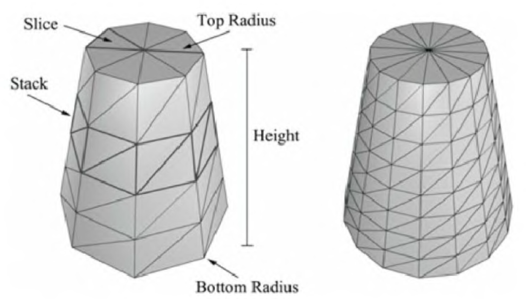
我们将圆柱体分为三个部分:侧面、顶部圆盖和底部圆盖。(注意这里说的圆柱体不是单纯的圆柱体,也可以泛指圆台、圆锥。当顶部圆盖半径为0就是圆锥。)我们可以定义一个圆柱体,通过指定其底部和顶部半径,还有高度,以及片(Slide)和层(Stack)数。如下图所示:

(图中左边的圆柱体有8片,4层。片数和层数可以控制三角形的密度。)
2. 如何产生圆柱体侧面网格?
上图有【层数+1】个环(ring),每个环都有片数个顶点。
每两个连续的环的半径之差△r为:
△r = (顶部圆盖半径 - 底部圆盖半径) / 层数
如果底部的环的下标是0,那么第i个环半径r(i):
r(i) = 底部环半径+ iΔr。
△h是层的高度,h是圆柱体高度。那么第i个环的高度h(i)是:
h(i) = -h/2 + i△h
所以我们的基本实现就是迭代每一环来产生每一环上的顶点。
那么如何指定索引呢?
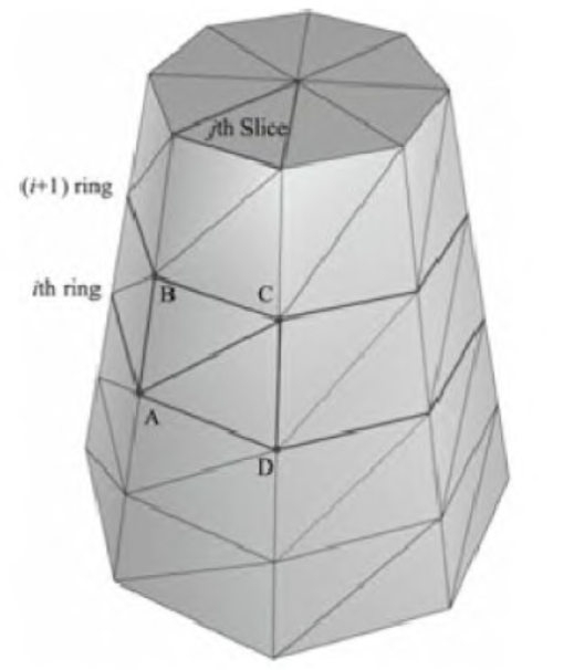
观察下图,每一层中的每一片都有一个四边形(两个三角形)。下图显示了第i层中的第j片:

(顶点 A,B,C,D包含第i层中的第j片)
ΔABC=(i·n+j, (i+1)·n+j), (i+1)·n+j+1)
ΔACD=(i·n+j, (i+1)·n+j+1, i·n+j+1
n是每一环的顶点数。因此,创建索引缓存的关键的思想是每一层中的每一片应用上述公式。
注意:
1. 每个环的第一个和最后一个顶点在位置上重复,但纹理坐标不重复。我们必须这样做才能正确地使用纹理。
2. 代码中包含创建圆柱体对象额外的顶点数据,例如法线和纹理坐标,这些为以后的演示提供方便,现在不用担心这些代码。
3. 产生圆柱体侧面网格源代码
void GeometryGenerator::CreateCylinder(float bottomRadius, float topRadius, float height, UINT sliceCount, UINT stackCount, MeshData& meshData)
{
    meshData.Vertices.clear();
    meshData.Indices.clear();

    //
    // 建立层
    //

    float stackHeight = height / stackCount;

    // 根据层的级数,自底向上增加半径的步长
    float radiusStep = (topRadius - bottomRadius) / stackCount;

    UINT ringCount = stackCount+1;

    // 自底向上计算每个层环的顶点
    for(UINT i = 0; i < ringCount; ++i)
    {
        float y = -0.5f*height + i*stackHeight;
        float r = bottomRadius + i*radiusStep;

        // 环的顶点
        float dTheta = 2.0f*XM_PI/sliceCount;
        for(UINT j = 0; j <= sliceCount; ++j)
        {
            Vertex vertex;

            float c = cosf(j*dTheta);
            float s = sinf(j*dTheta);

            vertex.Position = XMFLOAT3(r*c, y, r*s);

            vertex.TexC.x = (float)j/sliceCount;
            vertex.TexC.y = 1.0f - (float)i/stackCount;

            vertex.TangentU = XMFLOAT3(-s, 0.0f, c);

            float dr = bottomRadius-topRadius;
            XMFLOAT3 bitangent(dr*c, -height, dr*s);

            XMVECTOR T = XMLoadFloat3(&vertex.TangentU);
            XMVECTOR B = XMLoadFloat3(&bitangent);
            XMVECTOR N = XMVector3Normalize(XMVector3Cross(T, B));
            XMStoreFloat3(&vertex.Normal, N);

            meshData.Vertices.push_back(vertex);
        }
    }

    // 因为第一个顶点和最后一个顶点的贴图坐标是不同的,我们将顶点数加1
    UINT ringVertexCount = sliceCount+1;

    // 计算每层的顶点
    for(UINT i = 0; i < stackCount; ++i)
    {
        for(UINT j = 0; j < sliceCount; ++j)
        {
            meshData.Indices.push_back(i*ringVertexCount + j);
            meshData.Indices.push_back((i+1)*ringVertexCount + j);
            meshData.Indices.push_back((i+1)*ringVertexCount + j+1);

            meshData.Indices.push_back(i*ringVertexCount + j);
            meshData.Indices.push_back((i+1)*ringVertexCount + j+1);
            meshData.Indices.push_back(i*ringVertexCount + j+1);
        }
    }

    //下面两个函数调用产生顶部圆盖和底部圆盖网格,接下来会说到
    BuildCylinderTopCap(bottomRadius, topRadius, height, sliceCount, stackCount, meshData);
    BuildCylinderBottomCap(bottomRadius, topRadius, height, sliceCount, stackCount, meshData);
}
4. 如何产生圆柱体顶部圆盖网格和底面圆盖网格?(源代码实现)
原理就是产生一个顶部环足够多的片来近似产生一个圆,我们直接看源代码,底部和顶部的代码是几乎一样的:
void GeometryGenerator::BuildCylinderTopCap(float bottomRadius, float topRadius, float height,
                                            UINT sliceCount, UINT stackCount, MeshData& meshData)
{
    UINT baseIndex = (UINT)meshData.Vertices.size();

    float y = 0.5f*height;
    float dTheta = 2.0f*XM_PI/sliceCount;

    // 因为圆柱体顶部的环顶点的贴图坐标和法线向量是不同的,我们要复制顶部的顶点
    for(UINT i = 0; i <= sliceCount; ++i)
    {
        float x = topRadius*cosf(i*dTheta);
        float z = topRadius*sinf(i*dTheta);

        // Scale down by the height to try and make top cap texture coord area proportional to base.
        float u = x/height + 0.5f;
        float v = z/height + 0.5f;

        meshData.Vertices.push_back( Vertex(x, y, z, 0.0f, 1.0f, 0.0f, 1.0f, 0.0f, 0.0f, u, v) );
    }

    // 盖中心的顶点
    meshData.Vertices.push_back( Vertex(0.0f, y, 0.0f, 0.0f, 1.0f, 0.0f, 1.0f, 0.0f, 0.0f, 0.5f, 0.5f) );

    // 中心顶点的索引
    UINT centerIndex = (UINT)meshData.Vertices.size()-1;

    for(UINT i = 0; i < sliceCount; ++i)
    {
        meshData.Indices.push_back(centerIndex);
        meshData.Indices.push_back(baseIndex + i+1);
        meshData.Indices.push_back(baseIndex + i);
    }
}
void GeometryGenerator::BuildCylinderBottomCap(float bottomRadius, float topRadius, float height,
UINT sliceCount, UINT stackCount, MeshData& meshData)
{
//
// 建立底部盖
//
UINT baseIndex = (UINT)meshData.Vertices.size();
float y = -0.5f*height;
// 环的顶点
float dTheta = 2.0f*XM_PI/sliceCount;
for(UINT i = 0; i <= sliceCount; ++i)
{
float x = bottomRadius*cosf(i*dTheta);
float z = bottomRadius*sinf(i*dTheta);
// Scale down by the height to try and make top cap texture coord area proportional to base.
float u = x/height + 0.5f;
float v = z/height + 0.5f;
meshData.Vertices.push_back( Vertex(x, y, z, 0.0f, -1.0f, 0.0f, 1.0f


 该博客详细介绍了在DirectX11中如何生成圆柱体和球体的网格,包括圆柱体的侧面、顶部和底部网格以及球体的两种生成方法。内容涵盖算法原理、源代码实现以及最终的示例Demo,适用于游戏开发和图形渲染。
 最低0.47元/天 解锁文章


 4766
4766

 被折叠的 条评论
为什么被折叠?


