


声明:原文版权归属Intel®,这里仅作学习使用
来源:Intel® 64 and IA-32 Architectures Software Developer's Manual Volume 3A: System Programming Guide, Part 1
CHAPTER 2
SYSTEM ARCHITECTURE OVERVIEW 系统架构综述
IA-32 architecture (beginning with the Intel 386 processor family) provides extensive support for operating-system and system-development software. This support offers multiple modes of operation, which include:
- Real mode, protected mode, virtual 8086 mode, and system management mode. (实模式、保护模式、虚拟8086模式) These are sometimes referred to as legacy modes.
Intel 64 architecture supports almost all the system programming facilities available in IA-32 architecture and extends them to a new operating mode (IA-32e mode) that supports a 64-bit programming environment. IA-32e mode allows software to operate in one of two sub-modes:
- 64-bit mode supports 64-bit OS and 64-bit applications
- Compatibility mode allows most legacy software to run; it co-exists with 64-bit applications under a 64-bit OS.
The IA-32 system-level architecture and includes features to assist in the following operations:
- Memory management (内存管理)
- Protection of software modules (软件模块保护)
- Multitasking (多任务)
- Exception and interrupt handling (异常和中断处理)
- Multiprocessing (多处理)
- Cache management (缓存管理)
- Hardware resource and power management (硬件资源和电源管理)
- Debugging and performance monitoring (调试和性能监控)
This chapter provides a description of each part of this architecture. It also describes the system registers that are used to set up and control the processor at the system level and gives a brief overview of the processor’s system-level (operating system) instructions.
Many features of the system-level architectural are used only by system programmers.However, application programmers may need to read this chapter and the following chapters in order to create a reliable and secure environment for application programs.
This overview and most subsequent chapters of this book focus on protected-mode operation of the IA-32 architecture . IA-32e mode operation of the Intel 64 architecture, as it differs from protected mode operation, is also described.
All Intel 64 and IA-32 processors enter real-address mode following a power-up or reset(上电或重启之后进入实模式) (see Chapter 9, “Processor Management and Initialization”). Software then initiates the switch from real-address mode to protected mode.(软件负责将实模式转化到保护模式) If IA-32e mode operation is desired, software also initiates a switch from protected mode to IA-32e mode.
2.1 OVERVIEW OF THE SYSTEM-LEVEL ARCHITECTURE 系统级架构综述
System-level architecture consists of a set of registers, data structures, and instructions designed to support basic system-level operations such as memory management,interrupt and exception handling, task management, and control of multiple processors.
Figure 2-1 provides a summary of system registers and data structures that applies to 32-bit modes. System registers and data structures that apply to IA-32e mode are shown in Figure 2-2.
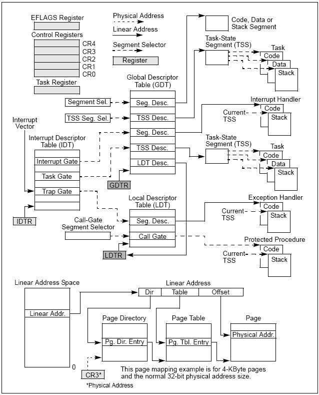
Figure 2-1. IA-32 System-Level Registers and Data Structures
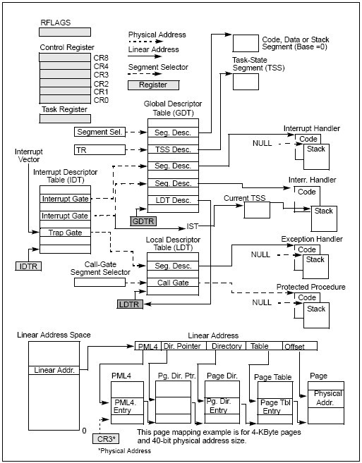
Figure 2-2. System-Level Registers and Data Structures in IA-32e Mode
2.1.1 Global and Local Descriptor Tables
When operating in protected mode, all memory accesses pass through either the global descriptor table (GDT) or an optional local descriptor table (LDT) as shown in Figure 2-1. These tables contain entries called segment descriptors(段描述符) . Segment descriptors provide the base address of segments well as access rights, type, and usage information(段基址以及访问权限、类型、使用信息).
Each segment descriptor has an associated segment selector. A segment selector provides the software that uses it with an index into the GDT or LDT (the offset of its associated segment descriptor), a global/local flag (determines whether the selector points to the GDT or the LDT), and access rights information .
To access a byte in a segment, a segment selector and an offset must be supplied(访问段中的一个字节,必须提供段选择符和偏移量). The segment selector provides access to the segment descriptor for the segment (in the GDT or LDT). From the segment descriptor, the processor obtains the base address of the segment in the linear address space. The offset then provides the location of the byte relative to the base address. This mechanism can be used to access any valid code, data, or stack segment, provided the segment is accessible from the current privilege level (CPL) at which the processor is operating. The CPL is defined as the protection level of the currently executing code segment.
See Figure 2-1. The solid arrows in the figure indicate a linear address, dashed lines indicate a segment selector, and the dotted arrows indicate a physical address. For simplicity, many of the segment selectors are shown as direct pointers to a segment. However, the actual path from a segment selector to its associated segment is always through a GDT or LDT.
The linear address of the base of the GDT is contained in the GDT register (GDTR) ; the linear address of the LDT is contained in the LDT register (LDTR) .
2.1.2 System Segments, Segment Descriptors, and Gates
Besides code, data, and stack segments that make up the execution environment of a program or procedure, the architecture defines two system segments: the task-state segment (TSS) and the LDT . The GDT is not considered a segment because it is not accessed by means of a segment selector and segment descriptor. TSSs and LDTs have segment descriptors defined for them.
The architecture also defines a set of special descriptors called gates (call gates, interrupt gates, trap gates, and task gates) (调用门、中断门、陷阱门、任务门) . These provide protected gateways to system procedures and handlers that may operate at a different privilege level than application programs and most procedures. For example, a CALL to a call gate can provide access to a procedure in a code segment that is at the same or a numerically lower privilege level (more privileged) than the current code segment. To access a procedure through a call gate, the calling procedure1 supplies the selector for the call gate. The processor then performs an access rights check on the call gate, comparing the CPL with the privilege level of the call gate and the destination code segment pointed to by the call gate.
If access to the destination code segment is allowed, the processor gets the segment selector for the destination code segment and an offset into that code segment from the call gate. If the call requires a change in privilege level, the processor also switches to the stack for the targeted privilege level. The segment selector for the new stack is obtained from the TSS for the currently running task. Gates also facilitate transitions between 16-bit and 32-bit code segments, and vice versa.
2.1.3 Task-State Segments and Task Gates
The TSS (see Figure 2-1) defines the state of the execution environment for a task (任务执行环境的状态) . It includes the state of general-purpose registers, segment registers, the EFLAGS register, the EIP register, and segment selectors with stack pointers for three stack segments (one stack for each privilege level) . The TSS also includes the segment selector for the LDT associated with the task and the page-table base address.
All program execution in protected mode happens within the context of a task (called the current task) (所有程序在当前任务的上下文内以保护模式执行) . The segment selector for the TSS for the current task is stored in the task register. The simplest method for switching to a task is to make a call or jump to the new task(切换任务的最简单的方法是通过call或者jmp新任务). Here, the segment selector for the TSS of the new task is given in the CALL or JMP instruction. In switching tasks, the processor performs the following actions:
1.Stores the state of the current task in the current TSS.
2.Loads the task register with the segment selector for the new task.
3.Accesses the new TSS through a segment descriptor in the GDT.
4.Loads the state of the new task from the new TSS into the general-purpose registers, the segment registers, the LDTR, control register CR3 (page-table base address), the EFLAGS register, and the EIP register.
5.Begins execution of the new task.
A task can also be accessed through a task gate. A task gate(任务门) is similar to a call gate, except that it provides access (through a segment selector) to a TSS rather than a code segment.
2.1.4 Interrupt and Exception Handling
External interrupts, software interrupts and exceptions are handled through the interrupt descriptor table (IDT)(外部中断、软件中断和异常通过终端描述符表处理) . The IDT stores a collection of gate descriptors that provide access to interrupt and exception handlers. Like the GDT, the IDT is not a segment. The linear address for the base of the IDT is contained in the IDT register (IDTR).
Gate descriptors in the IDT can be interrupt, trap, or task gate descriptors . To access an interrupt or exception handler, the processor first receives an interrupt vector (interrupt number) from internal hardware, an external interrupt controller, or from software by means of an INT, INTO, INT 3, or BOUND instruction. The interrupt vector provides an index into the IDT . If the selected gate descriptor is an interrupt gate or a trap gate, the associated handler procedure is accessed in a manner similar to calling a procedure through a call gate. If the descriptor is a task gate, the handler is accessed through a task switch.
2.1.5 Memory Management
System architecture supports either direct physical addressing of memory or virtual memory (through paging)(直接的物理寻址或者分页虚存) . When physical addressing is used, a linear address is treated as a physical address. When paging is used: all code, data, stack, and system segments (including the GDT and IDT) can be paged with only the most recently accessed pages being held in physical memory.
The location of pages (sometimes called page frames) in physical memory is contained in two types of system data structures: page directories(页目录) and page tables(页表) . Both structures reside in physical memory (see Figure 2-1).
The base physical address of the page directory is contained in control register CR3 . An entry in a page directory contains the physical address of the base of a page table, access rights and memory management information. An entry in a page table contains the physical address of a page frame, access rights and memory management information.
To use this paging mechanism, a linear address is broken into three parts . The parts provide separate offsets into the page directory, the page table, and the page frame . A system can have a single page directory or several. For example, each task can have its own page directory.
2.1.6 System Registers
To assist in initializing the processor and controlling system operations, the system architecture provides system flags in the EFLAGS register and several system registers:
•The system flags and IOPL field in the EFLAGS register control task and mode switching, interrupt handling, instruction tracing, and access rights . See also: Section 2.3, “System Flags and Fields in the EFLAGS Register.”
•The control registers (CR0, CR2, CR3, and CR4) contain a variety of flags and data fields for controlling system-level operations . Other flags in these registers are used to indicate support for specific processor capabilities within the operating system or executive. See also: Section 2.5, “Control Registers.”
•The debug registers (not shown in Figure 2-1) allow the setting of breakpoints for use in debugging programs and systems software. See also: Chapter 18, “Debugging and Performance Monitoring.”
•The GDTR, LDTR, and IDTR registers contain the linear addresses and sizes (limits) of their respective tables. See also: Section 2.4, “Memory-Management Registers.”
•The task register contains the linear address and size of the TSS for the current task. See also: Section 2.4, “Memory-Management Registers.”
•Model-specific registers (not shown in Figure 2-1).
The model-specific registers (MSRs) are a group of registers available primarily to operating-system or executive procedures (that is, code running at privilege level 0). These registers control items such as the debug extensions, the performance-monitoring counters, the machine- check architecture, and the memory type ranges (MTRRs).
The number and function of these registers varies among different members of the Intel 64 and IA-32 processor families. See also: Section 9.4, “Model-Specific Registers (MSRs),” and Appendix B, “Model-Specific Registers (MSRs).”
Most systems restrict access to system registers (other than the EFLAGS register) by application programs. Systems can be designed, however, where all programs and procedures run at the most privileged level (privilege level 0). In such a case, application programs would be allowed to modify the system registers.


 1479
1479

 被折叠的 条评论
为什么被折叠?
被折叠的 条评论
为什么被折叠?
 到【灌水乐园】发言


