


飞书文档![]() https://x509p6c8to.feishu.cn/wiki/Cczpw4oBeiyK71kFhKfcXkQmnad
https://x509p6c8to.feishu.cn/wiki/Cczpw4oBeiyK71kFhKfcXkQmnad
一、简介
IIC协议,又称I2C协议,是由PHILP公司在80年代开发的两线式串行总线,用于连接微控制器及其外围设备,IIC属于半双工同步通信方式。
| C |
多主控(multimastering)
其中任何能够进行发送和接收的设备都可以成为主总线,一个主控能够控制信号的传输和时钟频率。当然,在任何时间点上只能有一个主控。
特征:简单性和有效性
两根线,在标准模式下,I2C总线的最大长度为5米,最大速率为100 kbit/s。在快速模式下,I2C总线的最大长度为1米,最大速率为400 kbit/s。在高速模式下,I2C总线的最大长度为0.4米,最大速率为3.4 Mbit/s。需要注意的是,总线长度的实际限制还取决于总线上的电容负载和电缆质量等因素。
二、构成
IIC串行总线一般有两根信号线,一根是双向的数据线SDA,另一根是时钟线SCL,其时钟信号是由主控器件产生,数据线是用来传输数据的,时钟线是用来使双方通信的时钟同步。所有接到IIC总线设备上的串行数据SDA都接到总线的SDA上,各设备的时钟钱SCL接到总线的SCL上,对于并联在一条总线上的每个IC都有唯一的地址。
主机(master),就是老板,上班时间、下班时间、都是他来决定的,指令都是他来发出来的,他要找谁干啥,谁就干啥,一般主机就是我们的单片机。
从机(Slave),就是员工,需要做什么听老板的,一般从机就是外围设备,例如温湿度传感器、EEPROM芯片、测距仪等等IIC子设备。
硬件IIC与软件IIC
硬件IIC:芯片里面把IIC的通讯协议通过电路实现了,有专用的IIC引脚,只需要配置下寄存器就能实现IIC通讯;
软件IIC:根据IIC通讯的时序协议,自己找两个引脚,按照IIC协议的时序实现。
51是不支持硬件IIC的,所以我们要驱动IIC设备,只能通过代码实现软件IIC,简单来说就是通过IO口模拟IIC的时序。
50kbit/s = 1s 50k周期 = 1周期 =1/50ks = 20us
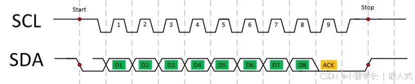
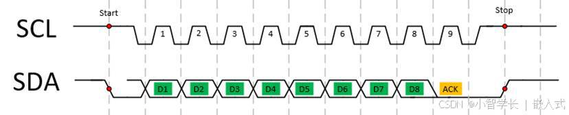
通过IIC传输一个Byte数据的时序如下:

IIC完成的通讯过程如下:
IIC完整的通讯过程
- 1、总线是空闲状态,SCL=1,SDA =1;
- 2、要开始传输数据了,此时SCL还是高电平,SCL=1,主机将SDA从1变成0;
- 3、跟哪个从机通讯,把从机的地址发出去。一般地址是8个bit(也有16个bit的),这8个bit其实真实的地址是7个bit,最后1个bit是用来表示读或者写的。1表示读,0表示写;这个过程相当于主机往SDA上发了8个bit的数据(地址也是数据啊);
- 4、主机发地址的过程,相当于在找从机,从机是要给应答信号的,就是ACK,你老板喊你,你也得先回答声A吧;
- 5、应答之后,就是要传输数据了,如果第3步中发的地址是写操作,那就由主机来控制SDA的电平变化,如果第3步中发的地址是读操作,那就由从机来控制SDA的电平变化;
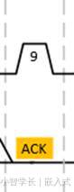
- 6、每次8bit的数据传输完成,都要有个应答信号,谁接收数据,谁来应答
- 7、完事之后,在SCL高电平时,主机把SDA从低电平拉高,表示结束。
10us延时函数
延时函数影响IIC速率
10us发送1bit,1ms=100bit 1s = 100kbit
void delay10us() //@11.0592MHz
{
unsigned char i;
i = 2;
while (--i);
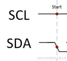
}起始信号:
发送数据前要先发送起始信号,告知总线和从机开始通讯
-SCL为高时,SDA从高变低

#include <reg52.h>
sbit sda = P0^1;
sbit scl = P0^2;
void i2c_start()
{
scl = 1;
sda = 1;
delay10us(); //起始信号建立时间,高电平时间持续大于4.7us
sda = 0; //SDA拉低,下降沿
delay10us(); //起始信号保持时间
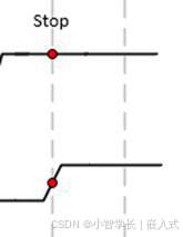
}结束信号:
发送完成需要发结束信号,告知总线和从机通讯完成
-SCL为高时,SDA从低变高
|
|
|

void i2c_stop()
{
        scl = 1;
        sda = 0;
        delay10us(); //停止信号建立时间,SDA高电平时间持续大于4.7us
        sda = 1;     //SDA拉高,上升沿
        delay10us(); //总线空闲时间保持
}
数据信号:
逐位发送数据或读取数据

0x20 = 0b0010 0000
发送1byte
1byte=8bit 发送1bit的流程是SCL拉低,SDA发送数据,维持一定时间,SCL拉高,维持一定时间,SCL拉低
单独实现:
void i2c_write_bit(unsigned char databit)
{
    scl = 0; //开始发送前,设置scl为0
    if(databit == 0) //设置需要发送的数据
        sda=0;
    else
        sda=1;
    delay5us();
    scl=1;
    delay10us();
    scl=0;
    delay5us();
}

void i2c_write_bit(unsigned char databit)
{
    scl = 0; //开始发送前,设置scl为0
    if(databit == 0) //设置需要发送的数据
        sda=0;
    else
        sda=1;
    delay10us();
    scl=1;
    delay10us();
    scl=0;
}

void i2c_write_byte(unsigned char datasend)
{
    for(i = 0; i < 8; i++){
        if(datasend & 0x80)
            i2c_write_bit(1);
        else
            i2c_write_bit(0);
        datasend=datasend<<1;//左移一位,for循环8次,直到数据发送完
    }
}
合二为一:
void i2c_write_byte(unsigned char datasend)//发送数据
{
        unsigned char i;
        for(i = 0; i < 8; i++)
        {
                scl = 0; //开始发送前,设置scl为0
                //判断最高位是1/0,是1设置sda输出高电平,是0设置sda输出低电平。
                if(datasend & 0x80)
                    sda=1;
                else
                    sda=0;
                datasend=datasend<<1;//左移一位,for循环8次,直到数据发送完
                delay10us();
                scl=1;
                delay10us();
                scl=0;
        }
}
读取1byte
1byte=8bit 接收1bit的流程是SCL拉低,延时5us,拉高SCL延时10us,等待数据稳定,读取SDA的值,SCL拉低,延时5us
单独实现
unsigned char i2c_read_bit(){
    unsigned char databit = 0;
    scl=0;   //每bit接收前,先设置scl为0
    delay5us();//scl为低电平的时间
    scl=1; //拉高scl开始接收数据
    delay10us();//等待数据稳定的时间
    if(sda)
       databit = 1;
    else
       databit = 0;
    scl=0;
    delay5us();
}

unsigned char i2c_read_bit(){
    unsigned char databit = 0;
    scl=0;   //每bit接收前,先设置scl为0
    delay10us();//scl为低电平的时间
    scl=1; //拉高scl开始接收数据
    delay10us();//等待数据稳定的时间
    if(sda)
       databit = 1;
    else
       databit = 0;
    return databit;
}

unsigned char i2c_read_byte()//接收数据
{
    unsigned char value = 0;
    sda=1;    //释放总线
    for(i=0;i<8;i++)
    {
        if(i2c_read_bit())
            value = value|0x01;
        if(i < 7)
            value = value << 1;
    }
    scl=0; //接收完成后,设置scl为0
    delay10us();
    return value;
}
合二为一
unsigned char i2c_read_byte()//接收数据
{
        int i,value;
        sda=1;    //释放总线
        for(i=0;i<8;i++)
        {
                scl=0; //每bit接收前,先设置scl为0
                delay10us();//scl为低电平的时间
                scl=1; //拉高scl开始接收数据
                delay10us();//等待数据稳定的时间
                value=value<<1;
                if(sda){
                //每次向左移动一位以后,如果sda=1的时候就把最后一位置1,sda=0的时候则不用置,因为向左移动就有一个0了
                    value=value|0x01;
                }
        }
        scl=0; //接收完成后,设置scl为0
        delay10us();
        return value;
}
应答信号:
完成数据发送后,通过读取应答信号判断从机是否收到数据
-应答信号:SCL从低到高再到低时,SDA都为低
-等待应答信号:SDA拉高(使得总线处于空闲状态),SCL从低到高时,检查SDA是否被拉低,如果被拉低,则获取到应答信号
0x55 - 0b0101 0101

|
|
|

//发送应答信号
void i2c_ack()
{
        scl = 0;
        sda = 0;     //SDA拉低,发出应答信号
        delay10us();
        scl = 1;
        delay10us();
        scl = 0;
}

//等待应答信号
unsigned char i2c_wait_ack()
{
        unsigned char ucErr = 0;
        sda = 1; //sda为高电平释放总线,然后检测应答信号是否被拉低
        scl = 0;
        delay10us();
        scl = 1;
        delay10us();
        while(sda)  //sda为高电平,就表示没有检查到ACK,
        {
                ucErr++;
                delay10us();
                if(ucErr > 250) //等一段时间,还没有ack,就停止总线
                {
                    return 1;
                }
        }
        scl = 0;
        return 0;
}
上节课补充
void i2c_wirte_byte(unsigned char datasend)
改为
void i2c_write_byte(unsigned char datasend)

void i2c_read_byte()
{
        unsigned char value = 0;
        unsigned char i = 0;
        sda = 0;
        for(i = 0;i < 8;i++){
                if(i2c_read_bit() == 1){
                        value = value | 0x01;
                }else{
                        value = value | 0x00;
                }
                if(i<7)
                        value = value << 1;
        }
        scl = 0;
        Delay10us();
}
添加返回值,改为
unsigned char i2c_read_byte()
{
        unsigned char value = 0;
        unsigned char i = 0;
        sda = 0;
        for(i = 0;i < 8;i++){
                if(i2c_read_bit() == 1){
                        value = value | 0x01;
                }else{
                        value = value | 0x00;
                }
                if(i<7)
                        value = value << 1;
        }
        scl = 0;
        Delay10us();
        return value;
}

修改读取数据前,SDA释放为1
1、总线空闲状态,SCL=1,SDA =1;
unsigned char i2c_read_byte()
{
        unsigned char value = 0;
        unsigned char i = 0;
        sda = 1;
        for(i = 0;i < 8;i++){
                if(i2c_read_bit() == 1){
                        value = value | 0x01;
                }else{
                        value = value | 0x00;
                }
                if(i<7)
                        value = value << 1;
        }
        scl = 0;
        Delay10us();
        return value;
}

添加nack函数
void i2c_nack()
{
        scl = 0;
        sda = 1;     //SDA拉高,发出非应答信号
        Delay10us();
        scl = 1;
        Delay10us();
        scl = 0;
}
三、温湿度传感器:CJ-GXHT3L
GXHT3L-DIS 是中科银河芯开发的新一代单芯片集成温湿度一 体传感器。
- ★ I2C 接口,通信速度高达 1MHz
- ★ 两个用户可选择的地址
- ★ GXHT3L 典型精度为±4%RH 和±0.5°C
- ★ GXHT30 典型精度为±3%RH 和±0.3°C
- ★ GXHT31 典型精度为±2%RH 和±0.3°C
- ★ 单芯片集成温湿传感器
- ★ 高可靠性和长期稳定性
- ★ 测量 0-100%范围相对湿度
- ★ 测量-45-130℃范围内温度
https://item.szlcsc.com/3199174.html
|
|
|
|
关于ADDR管脚说明:
这里要注意的是,0x44指的是I2C地址的高7位,第八位为读写标志位。
单次转换模式
|
|
|
例如:设置高重复率,开启长转换持续时间,读取测量得到的温湿度数据
0x44 0b0100 0100 0b1000 1000
连续转换模式
1、设置转换模式
高重复率和周期转换频率,例如0x2130中,21代表每秒转换一次,30代表高重复率。
0x44 -> 0b0100 0100
100 01000 -》地址+写标志
100 01001 -》 地址+读标志
//注意:addr=0x44时,实际发送到总线的数据应该是0x44+读写标志位,0 为写,1 为读
#define    GXHT3L_ADDR_WRITE    0x44<<1         //10001000
#define    GXHT3L_ADDR_READ     (0x44<<1)+1     //10001011

//MSB和LSB设置为0x2130 初始化进入连续转换模式,高重复率,每秒测量一次
void gxht30_init(){
    i2c_start();
    i2c_write_byte(GXHT3L_ADDR_WRITE);
    i2c_wait_ack();
    i2c_write_byte(0x21);
    i2c_wait_ack();
    i2c_write_byte(0x30);
    i2c_wait_ack();
    i2c_stop();
}2、进行数据读取
开始连续转换读取的命令0xE000
发送写标志+设备地址,发送开始连续指令(0xE000)
发送读标志+设备地址,等待SCL拉低,读取温湿度数据。
//周期测量模式读取数据命令
void gxht30_read_mode(){
    i2c_start();
    i2c_write_byte(GXHT3L_ADDR_WRITE);
    i2c_wait_ack();
    i2c_write_byte(0xE0);
    i2c_wait_ack();
    i2c_write_byte(0x00);
    i2c_wait_ack();
    i2c_stop();
}

void gxht30_read(){
    int index = 0;
    unsigned char buffer[6];
    i2c_start();
    i2c_write_byte(GXHT3L_ADDR_READ);
    i2c_wait_ack();
    /*
    buffer[0]=i2c_read_byte(1);//温度高8位
    i2c_ack();
    buffer[1]=i2c_read_byte(1);//温度低8位
    i2c_ack();
    buffer[2]=i2c_read_byte(1);//CRC
    i2c_ack();
    buffer[3]=i2c_read_byte(1);//湿度高8位
    i2c_ack();
    buffer[4]=i2c_read_byte(1);//湿度低9位
    i2c_ack();
    buffer[5]=i2c_read_byte(0);//CRC
    i2c_nack();
    i2c_stop();
    */
    for(index = 0;index < 6;index ++){
        buffer[index]=i2c_read_byte();
        if(index  == 5)
            i2c_nack();
        else
            i2c_ack();
    }
    i2c_stop();
}3、温湿度转换
void gxht30_read(){
    int index = 0;
    unsigned char buffer[6];
    unsigned short tem=0,hum=0;
    float temperature = 0.0;
    float humidity = 0.0;

    i2c_start();
    i2c_write_byte(GXHT3L_ADDR_READ);
    i2c_wait_ack();
    for(index = 0;index < 6;index ++){
        buffer[index]=i2c_read_byte();
        if(index  == 5)
            i2c_nack();
        else
            i2c_ack();
    }
    i2c_stop();
    //合并高低字节
    tem = ((buffer[0]<<8) | buffer[1]);
    hum = ((buffer[3]<<8) | buffer[4]);
    //进行温湿度转换
    temperature = (175.0*(float)tem/65535.0-45.0) ;// T = -45 + 175 * tem / (2^16-1)
    humidity = (100.0*(float)hum/65535.0);// RH = hum*100 / (2^16-1)
}4、CRC8校验
即循环冗余校核,是一种根据网络数据包或电脑文件等数据产生简短固定位数校核码的快速算法,主要用来检测或校核数据传输或者保存后可能出现的错误。
#define POLYNOMIAL  0x31   // P(x) = x^8 + x^5 + x^4 + 1 = 00110001

//CRC校验函数
unsigned char gxht30_crc8(unsigned char *crcdata, unsigned char nbrOfBytes)
{
  unsigned char Bit;        // bit mask
  unsigned char crc = 0xFF; // calculated checksum
  unsigned char byteCtr;    // byte counter
  for(byteCtr = 0; byteCtr < nbrOfBytes; byteCtr++)
  {
    crc ^= (crcdata[byteCtr]);
    for(Bit = 8; Bit > 0; --Bit)
    {
      if(crc & 0x80) crc = (crc << 1) ^ POLYNOMIAL;
      else           crc = (crc << 1);
    }
  }
  return crc;
}


void gxht30_read(){
    int index = 0;
    unsigned char buffer[6];
    unsigned short tem=0,hum=0;
    float temperature = 0.0;
    float humidity = 0.0;

    i2c_start();
    i2c_write_byte(GXHT3L_ADDR_READ);
    i2c_wait_ack();
    for(index = 0;index < 6;index ++){
        buffer[index]=i2c_read_byte();
        if(index  == 5)
            i2c_nack();
        else
            i2c_ack();
    }
    i2c_stop();
    if(buffer[2]!=gxht30_crc8(buffer,2))
        return;        //CRC错误,直接退出,不进行转换
    if(buffer[5]!=gxht30_crc8(&buffer[3],2))
        return;        //CRC错误,直接退出,不进行转换

    //合并高低字节
    tem = ((buffer[0]<<8) | buffer[1]);
    hum = ((buffer[3]<<8) | buffer[4]);
    //进行温湿度转换

    temperature = (175.0*(float)tem/65535.0-45.0) ;// T = -45 + 175 * tem / (2^16-1)
    humidity = (100.0*(float)hum/65535.0);// RH = hum*100 / (2^16-1)
    printf("temperature = %f, humidity = %f\n", temperature, humidity);
}5、串口打印温湿度
#include <stdio.h>
void uart_init(void)                //9600bps@11.0592MHz
{
        PCON &= 0x7F;                //波特率不倍速
        SCON = 0x50;                //8位数据,可变波特率
        TMOD &= 0x0F;                //清除定时器1模式位
        TMOD |= 0x20;                //设定定时器1为8位自动重装方式
        TL1 = 0xFD;                //设定定时初值
        TH1 = 0xFD;                //设定定时器重装值
        ET1 = 0;                //禁止定时器1中断
        TR1 = 1;                //启动定时器1
}

/*
**重写printf调用的putchar函数,重定向到串口输出
**需要引入头文件<stdio.h>
*****/
char putchar(char dat){
        //输出重定向到串口
        SBUF = dat;     //写入发送缓冲寄存器
        while(!TI);    //等待发送完成,TI发送溢出标志位 置1
        TI = 0;      //对溢出标志位清零
        return dat;  //返回给函数的调用者printf
}6、main函数实现
//带参延时函数
void delay_ms(unsigned int xms)   //@12MHz
{
    unsigned int i, j;
    for(i=xms;i>0;i--)
    {
        for(j=124;j>0;j--)
        {}
    }
}

void main()
{
        uart_init();
        gxht30_init();
        while(1)
        {
                delay_ms(1000);
                gxht30_read_mode();
                gxht30_read();

        }
}
最终工程:
#include <reg52.h>
#include <stdio.h>

sbit sda = P0^1;
sbit scl = P0^2;

#define GXHT3L_ADDR_WRITE 0x44<<1    //0b0100 0100 -> 0b1000 1000
#define GXHT3L_ADDR_READ  (0x44<<1)+1//0b0100 0100 -> 0b1000 1001

void Delay10us()                //@11.0592MHz
{
        unsigned char i;
        i = 2;
        while (--i);
}

void i2c_start()
{
        scl = 1;
        sda = 1;
        Delay10us();
        sda = 0;
}

void i2c_stop()
{
        scl = 1;
        sda = 0;
        Delay10us();
        sda = 1;
}

void i2c_write_bit(unsigned char databit)
{
        scl = 0;
        if(databit == 1)
                sda = 1;
        else
                sda = 0;
        Delay10us();
        scl = 1;
        Delay10us();
}

void i2c_write_byte(unsigned char datasend)
{
        int i = 0;
        for(i = 0;i< 8;i++){
                if(datasend & 0x80){
                        i2c_write_bit(1);
                }else{
                        i2c_write_bit(0);
                }
                datasend = datasend << 1;
        }
}

unsigned char i2c_read_bit()
{
        unsigned char databit = 0;
        scl = 0;
        Delay10us();
        scl = 1;
        Delay10us();
        if(sda == 1)
                databit =  1;
        else
                databit = 0;
        return databit;
}

unsigned char i2c_read_byte()
{
        unsigned char value = 0;
        unsigned char i = 0;
        sda = 1; //让总线处于空闲状态
        for(i = 0;i < 8;i++){
                if(i2c_read_bit() == 1){
                        value = value | 0x01;
                }else{
                        value = value | 0x00;
                }
                if(i<7)
                        value = value << 1;
        }
        scl = 0;
        Delay10us();
        return value;
}

void i2c_ack()
{
        scl = 0;
        sda = 0;
        Delay10us();
        scl = 1;
        Delay10us();
        scl = 0;
}

void i2c_nack()
{
  scl = 0;
  sda = 1;     //SDA拉高,发出非应答信号
  Delay10us();
  scl = 1;
  Delay10us();
  scl = 0;
}

void i2c_wait_ack()
{
        unsigned char time = 0;
        scl = 0;
        sda = 1;
        Delay10us();
        scl = 1;
        Delay10us();
        while(sda){
                Delay10us();
                time ++;
                if(time > 100)
                        break;
        }
        scl = 0;
        Delay10us();
}

void gxht30_init()
{
        i2c_start();
        i2c_write_byte(GXHT3L_ADDR_WRITE);
        i2c_wait_ack();
        i2c_write_byte(0x22);
        i2c_wait_ack();
        i2c_write_byte(0x20);
        i2c_wait_ack();
                                i2c_stop();
}

void gxht30_read_mode()
{
        i2c_start();
        i2c_write_byte(GXHT3L_ADDR_WRITE);
        i2c_wait_ack();
        i2c_write_byte(0xE0);
        i2c_wait_ack();
        i2c_write_byte(0x00);
        i2c_wait_ack();
                                i2c_stop();
                                Delay10us();
}

#define POLYNOMIAL  0x31   // P(x) = x^8 + x^5 + x^4 + 1 = 00110001

//CRC校验函数
unsigned char gxht30_crc8(unsigned char *crcdata, unsigned char nbrOfBytes)
{
  unsigned char Bit;        // bit mask
  unsigned char crc = 0xFF; // calculated checksum
  unsigned char byteCtr;    // byte counter
  for(byteCtr = 0; byteCtr < nbrOfBytes; byteCtr++)
  {
    crc ^= (crcdata[byteCtr]);
    for(Bit = 8; Bit > 0; --Bit)
    {
      if(crc & 0x80) crc = (crc << 1) ^ POLYNOMIAL;
      else           crc = (crc << 1);
    }
  }
  return crc;
}

void gxht30_read_data()
{
        unsigned short tem,hum;
        int index = 0;
        float temperature,humidity;
        unsigned char buffer[6];
        i2c_start();
        i2c_write_byte(GXHT3L_ADDR_READ);
        i2c_wait_ack();
        for(index = 0; index < 6;index ++){
                buffer[index] = i2c_read_byte();
                if(index == 5)
                        i2c_nack();
                else
                        i2c_ack();
        }
        i2c_stop();
                                if(gxht30_crc8(buffer,2) != buffer[2]){
                                        printf("crc error\n");
                                        return;
                                }
                                if(gxht30_crc8(&buffer[3],2) != buffer[5]){
                                        printf("crc error\n");
                                        return;
                                }
        //合并两个8bit的数据为一个16bit的数据
        tem = (buffer[0] << 8) | buffer[1];
        hum = (buffer[3] << 8) | buffer[4];
        //进行温湿度转换
        temperature = (175.0*(float)tem/65535.0-45.0) ;// T = -45 + 175 * tem / (2^16-1)
                                humidity = (100.0*(float)hum/65535.0);// RH = hum*100 / (2^16-1)
        printf("temperature=%f humidity=%f\n",temperature,humidity);
}


void uart_init(void)                //9600bps@11.0592MHz
{
        PCON &= 0x7F;                //波特率不倍速
        SCON = 0x50;                //8位数据,可变波特率
        TMOD &= 0x0F;                //清除定时器1模式位
        TMOD |= 0x20;                //设定定时器1为8位自动重装方式
        TL1 = 0xFD;                //设定定时初值
        TH1 = 0xFD;                //设定定时器重装值
        ET1 = 0;                //禁止定时器1中断
        TR1 = 1;                //启动定时器1
}

/*
**重写printf调用的putchar函数,重定向到串口输出
**需要引入头文件<stdio.h>
*****/
char putchar(char dat){
        //输出重定向到串口
        SBUF = dat;     //写入发送缓冲寄存器
        while(!TI);    //等待发送完成,TI发送溢出标志位 置1
        TI = 0;      //对溢出标志位清零
        return dat;  //返回给函数的调用者printf
}

//带参延时函数
void delay_ms(unsigned int xms)   //@12MHz
{
    unsigned int i, j;
    for(i=xms;i>0;i--)
    {
        for(j=124;j>0;j--)
        {}
    }
}

void main()
{
        uart_init();
        gxht30_init();
        while(1)
        {
                                                                delay_ms(1000);
                gxht30_read_mode();
                gxht30_read_data();

        }
}
FYI:
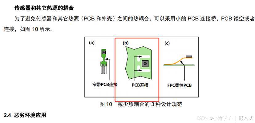
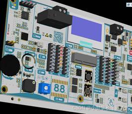
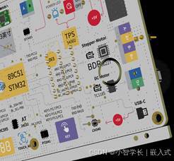
有的细心的小伙伴,在做这个实验的时候发现,从传感器读取的数据会比实际环境温度高1~2度,这是因为这块彩色板卡设计时,为了美观做的牺牲。
因为我们板卡工作时,电源模块会有温升,所以温湿度传感设计时得在芯片周边挖空开槽,或者使用插件的方式,但我们实际上打样回来后,发现实在太丑了。
|
|
|
|
考虑到大家在学习过程中,主要学习I2C的驱动原理,所以就取消了这个设计。


 337
337

 被折叠的 条评论
为什么被折叠?
被折叠的 条评论
为什么被折叠?
 到【灌水乐园】发言


