


题目:
Consider a finite state machine that is used to control some type of motor. The FSM has inputs x and y, which come from the motor, and produces outputs f and g, which control the motor. There is also a clock input called clk and a reset input called resetn.
The FSM has to work as follows. As long as the reset input is asserted, the FSM stays in a beginning state, called state A. When the reset signal is de-asserted, then after the next clock edge the FSM has to set the output f to 1 for one clock cycle. Then, the FSM has to monitor the x input. When x has produced the values 1, 0, 1 in three successive clock cycles, then g should be set to 1 on the following clock cycle. While maintaining g = 1 the FSM has to monitor the y input. If y has the value 1 within at most two clock cycles, then the FSM should maintain g = 1 permanently (that is, until reset). But if y does not become 1 within two clock cycles, then the FSM should set g = 0 permanently (until reset).
(The original exam question asked for a state diagram only. But here, implement the FSM.)
翻译:
考虑一个有限状态机,用于控制某种类型的电机。FSM有来自电机的输入x和y,并产生控制电机的输出f和g。还有一个时钟输入叫做clk,一个复位输入叫做resetn。FSM的工作原理如下:只要复位输入被断言,FSM就保持在开始状态,称为状态a。当复位信号被解除断言时,在下一个时钟边缘之后,FSM必须将输出f设置为1,持续一个时钟周期。然后,FSM必须监控x的输入。当x在三个连续的时钟周期中产生值1,0,1时,g应该在下一个时钟周期中设置为1。当保持g = 1时,FSM必须监视y的输入。如果y在最多两个时钟周期内的值为1,那么FSM应该永久保持g = 1(即直到重置)。但是如果y在两个时钟周期内没有变为1,那么FSM应该将g永久设置为0(直到重置)。(原来的考题只要求一个状态图。但在这里,实现FSM。)
Design Spec:
- 输入信号:clk;
- 输入信号:同步低电平复位信号:resetn;
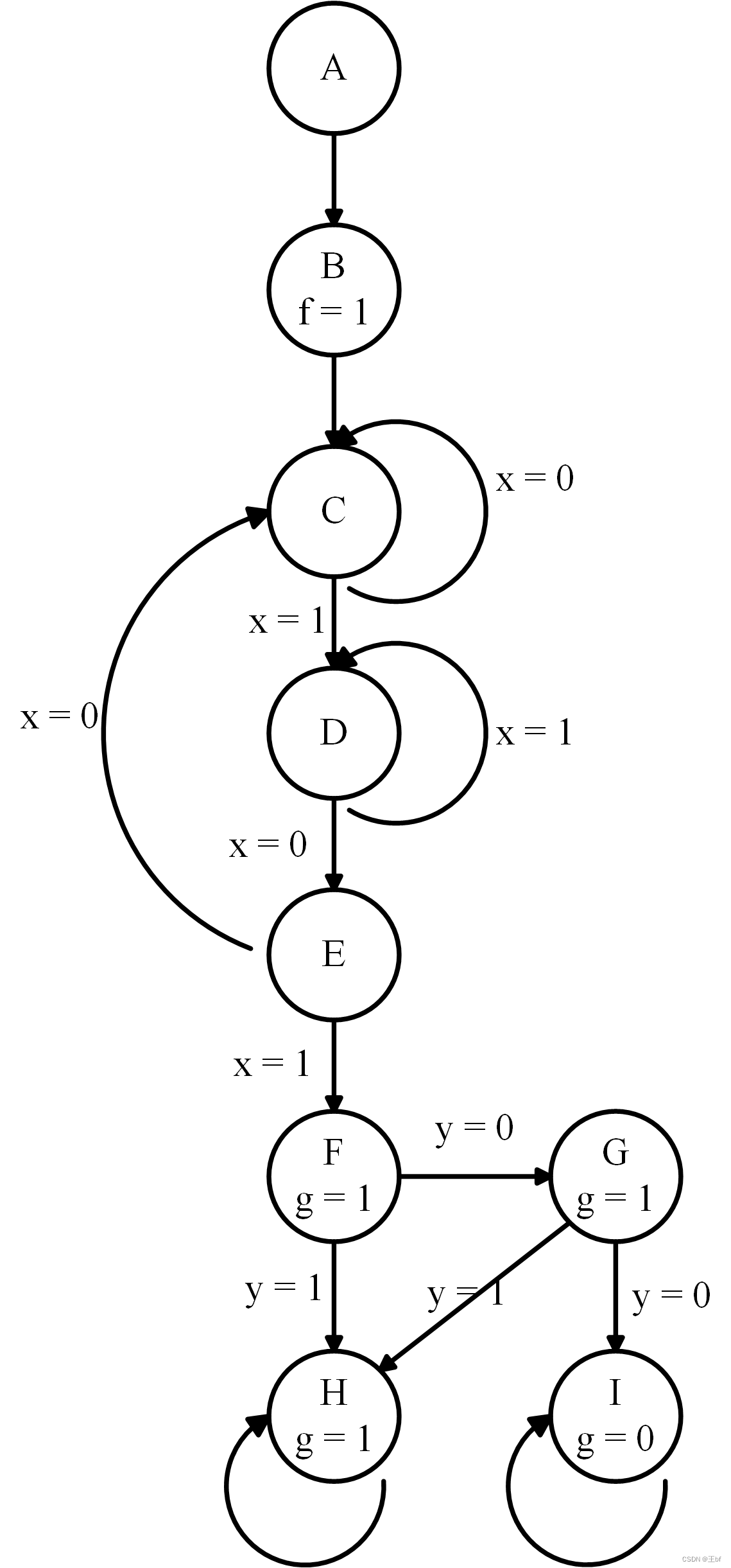
- 输入信号:x;//从状态 C 开始检测,检测到 101 跳出,且 g 赋值为 1。
- 输入信号:y;//从状态 F 开始检测
- 输出信号:f;//状态 B 时,输出为 1。
- 输出信号:g;//状态 F 时 g = 1,如果两个时钟周期内 y = 1,则 g 保持 1,否则,g = 0;
状态转移图:
RTL:
module top_module (
    input clk,
    input resetn,    // active-low synchronous reset
    input x,
    input y,
    output f,
    output g
);
    reg [3:0] state, next_state;
    parameter A = 4'd0, B = 4'd1, C = 4'd2;
    parameter D = 4'd3, E = 4'd4, F = 4'd5;
    parameter G = 4'd6, H = 4'd7, I = 4'd8;

    always@(posedge clk) begin
        if(~resetn) begin
        	state <= A;
        end
        else begin
            state <= next_state;
        end
    end

    always@(*) begin
        case(state)
            A:	next_state = B;
            B:	next_state = C;
            C:	begin
                if(x) begin
                   	next_state = D;
                end
                else begin
                   	next_state = C;
                end
            end
            D:	begin
                if(~x) begin
                   	next_state = E;
                end
                else begin
                   	next_state = D;
                end
            end
            E:	begin
                if(x) begin
                   	next_state = F;
                end
                else begin
                   	next_state = C;
                end
            end
            F:	begin
                if(y) begin
                   	next_state = H;
                end
                else begin
                   	next_state = G;
                end
            end
            H:	next_state = H;
            G:	begin
                if(y) begin
                   	next_state = H;
                end
                else begin
                   	next_state = I;
                end
            end
            I:	next_state = I;
        endcase
    end

    assign f = (state == B)?1'b1:1'b0;
    assign g = (state == H || state == F || state == G)?1'b1:1'b0;

endmodule
TB:
module test;
reg clk;
reg resetn;
reg x;
reg y;
wire f;
wire g;
top_module u0(
.clk(clk),
.resetn(resetn),
.x(x),
.y(y),
.f(f),
.g(g)
);
initial begin
clk = 0;
resetn = 0;
x = 0;
y = 0;
#30 resetn = 1;
end
always #10 clk = ~clk;
always #500 begin
resetn = 0;
#30 resetn = 1;
end
always@(posedge clk) begin
if(({$random()}%2)<1) begin
x = 1;
end
else x = 0;
end
always@(posedge clk) begin
if(({$random()}%2)<1) begin
y = 1;
end
else y = 0;
end
initial begin
#10000 $finish;
end
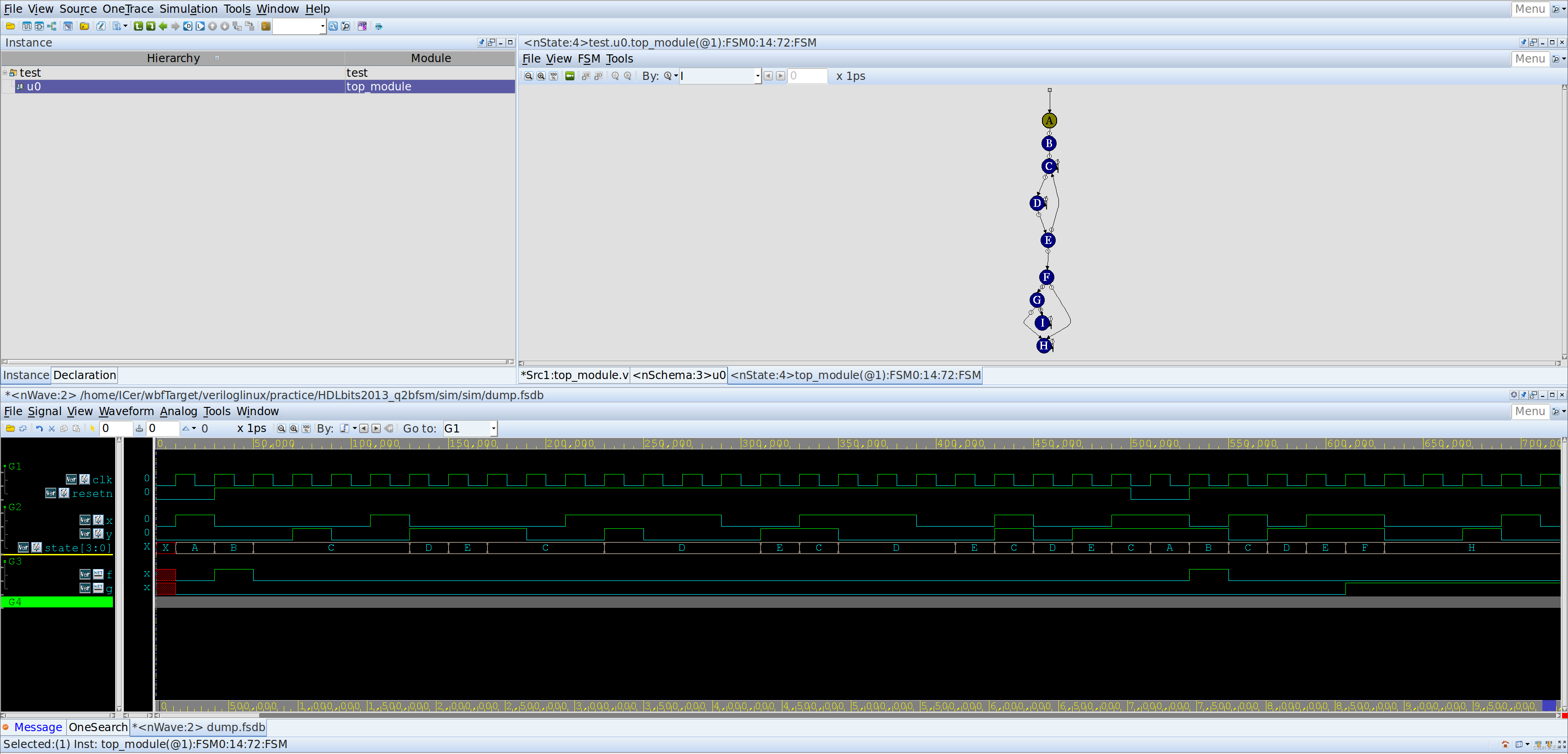
endmodule波形图:


 764
764


 被折叠的 条评论
为什么被折叠?
被折叠的 条评论
为什么被折叠?
 到【灌水乐园】发言


