


3.8 The Pixel Shader 像素着色器
After the vertex, tessellation, and geometry shaders perform their operations, the primitive is clipped and set up for rasterization, as explained in the previous chapter. This section of the pipeline is relatively fixed in its processing steps, i.e., not programmable but somewhat configurable. Each triangle is traversed to determine which pixels it covers. The rasterizer may also roughly calculate how much the triangle covers each pixel’s cell area (Section 5.4.2). This piece of a triangle partially or fully overlapping the pixel is called a fragment.
在顶点、曲面细分和几何着色器执行它们的操作之后,图元被裁剪并设置为光栅化,如前一章所述。 流水线的这一部分在其处理步骤中相对固定,即不可编程但有些可配置。 遍历每个三角形以确定它覆盖了哪些像素。 光栅化器也可以粗略地计算三角形覆盖每个像素单元区域的程度(第 5.4.2 节)。 部分或完全重叠像素的这片三角形称为片段。
The values at the triangle’s vertices, including the z-value used in the z-buffer, are interpolated across the triangle’s surface for each pixel. These values are passed to the pixel shader, which then processes the fragment. In OpenGL the pixel shader is known as the fragment shader, which is perhaps a better name. We use “pixel shader” throughout this book for consistency. Point and line primitives sent down the pipeline also create fragments for the pixels covered.
三角形顶点处的值(包括 z 缓冲区中使用的 z 值)针对每个像素在三角形表面进行插值。 这些值被传递给像素着色器,然后由像素着色器处理片段。 在 OpenGL 中,像素着色器被称为片段着色器,这也许是一个更好的名称。 为了保持一致性,我们在整本书中都使用“像素着色器”。 沿着管道发送的点和线基元也会为覆盖的像素创建片段。
The type of interpolation performed across the triangle is specified by the pixel shader program. Normally we use perspective-correct interpolation, so that the worldspace distances between pixel surface locations increase as an object recedes in the distance. An example is rendering railroad tracks extending to the horizon. Railroad ties are more closely spaced where the rails are farther away, as more distance is traveled for each successive pixel approaching the horizon. Other interpolation options are available, such as screen-space interpolation, where perspective projection is not taken into account. DirectX 11 gives further control over when and how interpolation is performed [530].
在三角形上执行的插值类型由像素着色器程序指定。 通常我们使用透视校正插值,这样像素表面位置之间的世界空间距离随着物体在距离上的后退而增加。 一个例子是渲染延伸到地平线的铁轨。 铁路枕木在铁轨距离较远的地方间隔更近,因为每个连续的像素接近地平线的距离更长。 其他插值选项可用,例如屏幕空间插值,其中不考虑透视投影。 DirectX 11 可以进一步控制何时以及如何执行插值 [530]。
In programming terms, the vertex shader program’s outputs, interpolated across the triangle (or line), effectively become the pixel shader program’s inputs. As the GPU has evolved, other inputs have been exposed. For example, the screen position of the fragment is available to the pixel shader in Shader Model 3.0 and beyond. Also, which side of a triangle is visible is an input flag. This knowledge is important for rendering a different material on the front versus back of each triangle in a single pass.
在编程术语中,顶点着色器程序的输出,在三角形(或直线)上进行插值,有效地成为像素着色器程序的输入。 随着 GPU 的发展,其他输入也被暴露出来。 例如,片段的屏幕位置可用于 Shader Model 3.0 及更高版本中的像素着色器。 此外,三角形的哪一侧可见是输入标志。 此知识对于在单个通道中在每个三角形的正面和背面渲染不同的材质非常重要。
With inputs in hand, typically the pixel shader computes and outputs a fragment’s color. It can also possibly produce an opacity value and optionally modify its z-depth. During merging, these values are used to modify what is stored at the pixel. The depth value generated in the rasterization stage can also be modified by the pixel shader. The stencil buffer value is usually not modifiable, but rather it is passed through to the merge stage. DirectX 11.3 allows the shader to change this value. Operations such as fog computation and alpha testing have moved from being merge operations to being pixel shader computations in SM 4.0 [175].
有了输入,像素着色器通常会计算并输出片段的颜色。 它还可能会产生一个不透明度值并可选择修改其 z 深度。 在合并期间,这些值用于修改存储在像素中的内容。 在光栅化阶段生成的深度值也可以被像素着色器修改。 模板缓冲区值通常是不可修改的,而是传递到合并阶段。 DirectX 11.3 允许着色器更改此值。 在 SM 4.0 [175] 中,雾计算和 alpha 测试等操作已经从合并操作转变为像素着色器计算。
A pixel shader also has the unique ability to discard an incoming fragment, i.e., generate no output. One example of how fragment discard can be used is shown in Figure 3.14. Clip plane functionality used to be a configurable element in the fixedfunction pipeline and was later specified in the vertex shader. With fragment discard available, this functionality could then be implemented in any way desired in the pixel shader, such as deciding whether clipping volumes should be AND’ed or OR’ed together.
像素着色器还具有丢弃传入片段的独特能力,即不生成任何输出。 图 3.14 显示了如何使用片段丢弃的一个示例。 裁剪平面功能曾经是固定功能管道中的可配置元素,后来在顶点着色器中指定。 有了片段丢弃可用,这个功能就可以在像素着色器中以任何需要的方式实现,例如决定剪切体积是否应该被“与”或“或”在一起。
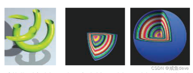
Figure 3.14. User-defined clipping planes. On the left, a single horizontal clipping plane slices the object. In the middle, the nested spheres are clipped by three planes. On the right, the spheres’ surfaces are clipped only if they are outside all three clip planes. (From the three.js examples webgl_clipping and webgl_clipping_intersection [218].)
图 3.14。 用户定义的剪裁平面。 在左侧,单个水平裁剪平面将对象切片。 在中间,嵌套的球体被三个平面剪裁。 在右侧,只有在所有三个裁剪平面之外的球体表面才会被裁剪。 (来自 three.js 示例 webgl_clipping 和 webgl_clipping_intersection [218]。)
Initially the pixel shader could output to only the merging stage, for eventual display. The number of instructions a pixel shader can execute has grown considerably over time. This increase gave rise to the idea of multiple render targets (MRT). Instead of sending results of a pixel shader’s program to just the color and z-buffer, multiple sets of values could be generated for each fragment and saved to different buffers, each called a render target. Render targets generally have the same x- and y-dimensions; some APIs allow different sizes, but the rendered area will be the smallest of these. Some architectures require render targets to each have the same bit depth, and possibly even identical data formats. Depending on the GPU, the number of render targets available is four or eight.
最初,像素着色器只能输出到合并阶段,以供最终显示。 随着时间的推移,像素着色器可以执行的指令数量大幅增加。 这种增加引发了多渲染目标 (MRT) 的想法。 不是将像素着色器程序的结果发送到颜色和 z 缓冲区,而是可以为每个片段生成多组值并保存到不同的缓冲区,每个缓冲区称为渲染目标。 渲染目标通常具有相同的 x 和 y 维度; 一些 API 允许不同的大小,但渲染区域将是其中最小的。 一些架构要求每个渲染目标都具有相同的位深度,甚至可能具有相同的数据格式。 根据 GPU,可用渲染目标的数量为四个或八个。
Even with these limitations, MRT functionality is a powerful aid in performing rendering algorithms more efficiently. A single rendering pass could generate a color image in one target, object identifiers in another, and world-space distances in a third. This ability has also given rise to a different type of rendering pipeline, called deferred shading, where visibility and shading are done in separate passes. The first pass stores data about an object’s location and material at each pixel. Successive passes can then efficiently apply illumination and other effects. This class of rendering methods is described in Section 20.1.
即使有这些限制,MRT 功能仍然是更有效地执行渲染算法的有力帮助。 单个渲染通道可以在一个目标中生成彩色图像,在另一个目标中生成对象标识符,在第三个中生成世界空间距离。 这种能力还产生了一种不同类型的渲染管道,称为延迟着色,其中可见性和着色在单独的通道中完成。 第一遍在每个像素处存储有关对象位置和材料的数据。 然后连续的通道可以有效地应用照明和其他效果。 此类呈现方法在第 20.1 节中描述。
The pixel shader’s limitation is that it can normally write to a render target at only the fragment location handed to it, and cannot read current results from neighboring pixels. That is, when a pixel shader program executes, it cannot send its output directly to neighboring pixels, nor can it access others’ recent changes. Rather, it computes results that affect only its own pixel. However, this limitation is not as severe as it sounds. An output image created in one pass can have any of its data accessed by a pixel shader in a later pass. Neighboring pixels can be processed using image processing techniques, described in Section 12.1.
像素着色器的限制是它通常只能在传递给它的片段位置写入渲染目标,而不能从相邻像素读取当前结果。 也就是说,当像素着色器程序执行时,它不能将其输出直接发送到相邻像素,也不能访问其他人最近的更改。 相反,它计算仅影响其自身像素的结果。 然而,这种限制并不像听起来那么严重。 在一个通道中创建的输出图像可以在后面的通道中由像素着色器访问其任何数据。 可以使用第 12.1 节中描述的图像处理技术来处理相邻像素。
There are exceptions to the rule that a pixel shader cannot know or affect neighboring pixels’ results. One is that the pixel shader can immediately access information for adjacent fragments (albeit indirectly) during the computation of gradient or derivative information. The pixel shader is provided with the amounts by which any interpolated value changes per pixel along the x and y screen axes. Such values are useful for various computations and texture addressing. These gradients are particularly important for operations such as texture filtering (Section 6.2.2), where we want to know how much of an image covers a pixel. All modern GPUs implement this feature by processing fragments in groups of 2 x 2, called a quad. When the pixel shader requests a gradient value, the difference between adjacent fragments is returned. See Figure 3.15. A unified core has this capability to access neighboring data—kept in different threads on the same warp—and so can compute gradients for use in the pixel shader. One consequence of this implementation is that gradient information cannot be accessed in parts of the shader affected by dynamic flow control, i.e., an “if” statement or loop with a variable number of iterations. All the fragments in a group must be processed using the same set of instructions so that all four pixels’ results are meaningful for computing gradients. This is a fundamental limitation that exists even in offline rendering systems [64].
像素着色器无法知道或影响相邻像素结果的规则也有例外。 一是像素着色器可以在计算梯度或导数信息期间立即访问相邻片段的信息(尽管是间接的)。 像素着色器提供了沿 x 和 y 屏幕轴的每个像素的任何插值变化量。 这些值对于各种计算和纹理寻址很有用。 这些梯度对于纹理过滤(第 6.2.2 节)等操作特别重要,我们想知道有多少图像覆盖了一个像素。 所有现代 GPU 都通过以 2 x 2 为一组(称为四边形)处理片段来实现此功能。 当像素着色器请求梯度值时,返回相邻片段之间的差异。 见图 3.15。 统一核心具有访问相邻数据的能力——保存在同一个 warp 上的不同线程中——因此可以计算在像素着色器中使用的梯度。 此实现的一个后果是无法在受动态流控制影响的着色器部分访问梯度信息,即“if”语句或具有可变迭代次数的循环。 一组中的所有片段必须使用相同的指令集进行处理,以便所有四个像素的结果对计算梯度都有意义。 这是即使在离线渲染系统中也存在的基本限制 [64]。
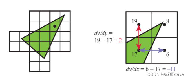
Figure 3.15. On the left, a triangle is rasterized into quads, sets of 2 x 2 pixels. The gradient computations for the pixel marked with a black dot is then shown on the right. The value for v is shown for each of the four pixel locations in the quad. Note how three of the pixels are not covered by the triangle, yet they are still processed by the GPU so that the gradients can be found. The gradients in the x and y screen directions are computed for the lower left pixel by using its two quad neighbors.
图 3.15。 在左侧,一个三角形被栅格化为四边形,每组 2 x 2 像素。 然后右侧显示了用黑点标记的像素的梯度计算。 为四边形中的四个像素位置中的每一个显示 v 的值。 请注意,其中三个像素未被三角形覆盖,但它们仍由 GPU 处理,以便可以找到梯度。 x 和 y 屏幕方向的梯度是通过使用它的两个四边形邻居为左下像素计算的。
DirectX 11 introduced a buffer type that allows write access to any location, the unordered access view (UAV). Originally for only pixel and compute shaders, access to UAVs was extended to all shaders in DirectX 11.1 [146]. OpenGL 4.3 calls this a shader storage buffer object (SSBO). Both names are descriptive in their own way. Pixel shaders are run in parallel, in an arbitrary order, and this storage buffer is shared among them.
DirectX 11 引入了一种缓冲区类型,允许对任何位置进行写入访问,即无序访问视图 (UAV)。 最初仅适用于像素和计算着色器,对无人机的访问扩展到 DirectX 11.1 [146] 中的所有着色器。 OpenGL 4.3 将其称为着色器存储缓冲区对象 (SSBO)。 这两个名称都以自己的方式进行描述。 像素着色器以任意顺序并行运行,并且此存储缓冲区在它们之间共享。
Often some mechanism is needed to avoid a data race condition (a.k.a. a data hazard), where both shader programs are “racing” to influence the same value, possibly leading to arbitrary results. As an example, an error could occur if two invocations of a pixel shader tried to, say, add to the same retrieved value at about the same time. Both would retrieve the original value, both would modify it locally, but then whichever invocation wrote its result last would wipe out the contribution of the other invocation—only one addition would occur. GPUs avoid this problem by having dedicated atomic units that the shader can access [530]. However, atomics mean that some shaders may stall as they wait to access a memory location undergoing read/modify/write by another shader.
通常需要一些机制来避免数据竞争条件(也称为数据危害),其中两个着色器程序“竞争”以影响相同的值,可能导致任意结果。 例如,如果像素着色器的两次调用试图在大约同一时间添加到相同的检索值,则可能会发生错误。 两者都将检索原始值,都将在本地修改它,但是无论哪个调用最后写入其结果都会消除另一个调用的贡献——只会发生一次添加。 GPU 通过拥有着色器可以访问的专用原子单元来避免这个问题 [530]。 然而,原子性意味着一些着色器可能会在等待访问正在被另一个着色器读取/修改/写入的内存位置时停止。
While atomics avoid data hazards, many algorithms require a specific order of execution. For example, you may want to draw a more distant transparent blue triangle before overlaying it with a red transparent triangle, blending the red atop the blue. It is possible for a pixel to have two pixel shader invocations for a pixel, one for each triangle, executing in such a way that the red triangle’s shader completes before the blue’s. In the standard pipeline, the fragment results are sorted in the merger stage before being processed. Rasterizer order views (ROVs) were introduced in DirectX 11.3 to enforce an order of execution. These are like UAVs; they can be read and written by shaders in the same fashion. The key difference is that ROVs guarantee that the data are accessed in the proper order. This increases the usefulness of these shader-accessible buffers considerably [327, 328]. For example, ROVs make it possible for the pixel shader to write its own blending methods, since it can directly access and write to any location in the ROV, and thus no merging stage is needed [176]. The price is that, if an out-of-order access is detected, a pixel shader invocation may stall until triangles drawn earlier are processed.
虽然原子避免了数据危害,但许多算法需要特定的执行顺序。 例如,您可能想要绘制一个更远的透明蓝色三角形,然后再用红色透明三角形覆盖它,将红色混合在蓝色之上。 一个像素可能有两个像素着色器调用,每个三角形一个,以红色三角形的着色器在蓝色三角形着色器之前完成的方式执行。 在标准管道中,片段结果在处理之前在合并阶段进行排序。 DirectX 11.3 中引入了光栅化顺序视图 (ROV) 以强制执行顺序。 这些就像无人机; 它们可以由着色器以相同的方式读取和写入。 关键区别在于 ROV 保证以正确的顺序访问数据。 这大大增加了这些着色器可访问缓冲区的实用性 [327、328]。 例如,ROV 使像素着色器可以编写自己的混合方法,因为它可以直接访问和写入 ROV 中的任何位置,因此不需要合并阶段 [176]。 代价是,如果检测到乱序访问,像素着色器调用可能会停止,直到处理完之前绘制的三角形。


 1005
1005


 被折叠的 条评论
为什么被折叠?
被折叠的 条评论
为什么被折叠?
 到【灌水乐园】发言


