


Arduino ESP32 ADC功能介绍以及模拟量信号读取示例
✨本篇文章展示如何使用Arduino IDE读取与ESP32模拟输入。模拟读数对于读出可变电阻(如电位器或模拟传感器)的值很有用。
- 📍关于ESP32 ADC功能英文介绍在参考手册:https://docs.espressif.com/projects/esp-idf/zh_CN/latest/esp32/api-reference/peripherals/adc.html
📗ADC引脚
- ADC1:
8通道:GPIO32 - GPIO39
- ADC2:
10个通道:GPIO0、GPIO2、GPIO4、GPIO12-GPIO15、GOIO25-GPIO27
typedef enum {
    ADC1_CHANNEL_0 = 0, /*!< ADC1 channel 0 is GPIO36 */
    ADC1_CHANNEL_1,     /*!< ADC1 channel 1 is GPIO37 */
    ADC1_CHANNEL_2,     /*!< ADC1 channel 2 is GPIO38 */
    ADC1_CHANNEL_3,     /*!< ADC1 channel 3 is GPIO39 */
    ADC1_CHANNEL_4,     /*!< ADC1 channel 4 is GPIO32 */
    ADC1_CHANNEL_5,     /*!< ADC1 channel 5 is GPIO33 */
    ADC1_CHANNEL_6,     /*!< ADC1 channel 6 is GPIO34 */
    ADC1_CHANNEL_7,     /*!< ADC1 channel 7 is GPIO35 */
    ADC1_CHANNEL_MAX,
} adc1_channel_t;

typedef enum {
    ADC2_CHANNEL_0 = 0, /*!< ADC2 channel 0 is GPIO4 */
    ADC2_CHANNEL_1,     /*!< ADC2 channel 1 is GPIO0 */
    ADC2_CHANNEL_2,     /*!< ADC2 channel 2 is GPIO2 */
    ADC2_CHANNEL_3,     /*!< ADC2 channel 3 is GPIO15 */
    ADC2_CHANNEL_4,     /*!< ADC2 channel 4 is GPIO13 */
    ADC2_CHANNEL_5,     /*!< ADC2 channel 5 is GPIO12 */
    ADC2_CHANNEL_6,     /*!< ADC2 channel 6 is GPIO14 */
    ADC2_CHANNEL_7,     /*!< ADC2 channel 7 is GPIO27 */
    ADC2_CHANNEL_8,     /*!< ADC2 channel 8 is GPIO25 */
    ADC2_CHANNEL_9,     /*!< ADC2 channel 9 is GPIO26 */
    ADC2_CHANNEL_MAX,
} adc2_channel_t;
使用ESP32读取模拟输入就像使用analogRead(GPIO)函数一样简单,它接受要读取的GPIO作为参数。
📄ADC2使用限制说明
- Wi-Fi 驱动程序使用了 ADC2。因此,应用程序只能在未启动 Wi-Fi 驱动程序时使用 ADC2。
- 有些
ADC2引脚作为Strapping管脚引脚(GPIO 0,2,15),因此无法自由使用。 ESP32 DevKitC型号 : 由于外部自动编程电路,无法使用 GPIO 0。ESP-WROVER-KIT型号 : GPIO 0, 2, 4 和 15 由于不同用途的外部连接而无法使用。
- 🎈管脚具体说明,可以参考说明:
https://docs.espressif.com/projects/esp-idf/zh_CN/stable/esp32/api-reference/peripherals/gpio.html
📒ADC 采样模式
每个 ADC 单元支持两种工作模式,ADC 单次采样模式和ADC连续采样(DMA)模式。
- ADC 单次采样模式适用于低频采样操作。
- ADC 连续采样(DMA)模式适用于高频连续采样动作。
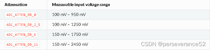
📑衰减倍数
- 不同的衰减倍数对应不同的检测电压范围。
ADC的默认满量程电压为1.1V。要读取更高的电压(最高为引脚最大电压,通常为3.3V),则需要将该ADC通道的信号衰减设置为> 0dB。
-
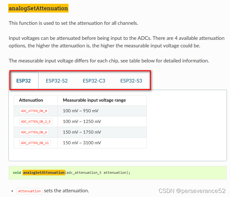
👉针对不型号参数差异:可以参考:
https://docs.espressif.com/projects/arduino-esp32/en/latest/api/adc.html?highlight=analogsetattenuation
-
当VDD_A为3.3V时:
0dB衰减(ADC_ATTEN_0db)表示参考电压为1.1V
2.5dB衰减(ADC_ATTEN_2_5db)表示参考电压为1.5V
6dB衰减(ADC_ATTEN_6db)表示参考电压为2.2V
11dB衰减(ADC_ATTEN_11db)表示参考电压为3.9V
Arduino ESP32 核心库有关ADC库函数
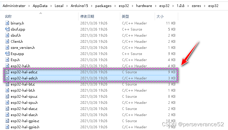
esp32-hal-adc.h
#ifndef MAIN_ESP32_HAL_ADC_H_
#define MAIN_ESP32_HAL_ADC_H_

#ifdef __cplusplus
extern "C" {
#endif

#include "esp32-hal.h"
/*
衰减倍数
0dB衰减(ADC_ATTEN_0db)表示参考电压为1.1V
2.5dB衰减(ADC_ATTEN_2_5db)表示参考电压为1.5V
6dB衰减(ADC_ATTEN_6db)表示参考电压为2.2V
11dB衰减(ADC_ATTEN_11db)表示参考电压为3.9V
*/
typedef enum {
    ADC_0db,
    ADC_2_5db,
    ADC_6db,
    ADC_11db
} adc_attenuation_t;

/*
 * 获取引脚的ADC值
 * */
uint16_t analogRead(uint8_t pin);

/*
*设置analogRead返回值的分辨率。缺省值是12位(0 ~ 4096)。
*如果在9和12之间,它将等于设置的硬件分辨率,否则值将被移动。
*范围为1 - 16
 *
 * 注:兼容Arduino SAM
 */
void analogReadResolution(uint8_t bits);

/*
*设置示例位和读取分辨率
*默认为12bit (0 - 4095)
*范围是9 - 12
 * */
void analogSetWidth(uint8_t bits);

/*
*设置ADC时钟的分压器。
*默认值为1
*取值范围为1 - 255
 * */
void analogSetClockDiv(uint8_t clockDiv);

/*
 * Set the attenuation for all channels
 * Default is 11db
 * */
void analogSetAttenuation(adc_attenuation_t attenuation);

/*
*设置所有通道的衰减
*默认为11db
 * */
void analogSetPinAttenuation(uint8_t pin, adc_attenuation_t attenuation);

/*
 * 获取霍尔传感器的值(无LNA)
*	连接到引脚36(SVP)和引脚39(SVN)
 * */
int hallRead();

/*
 *将引脚连接到ADC(也将清除任何其他模拟模式,可以打开)
 * */
bool adcAttachPin(uint8_t pin);

/*设置引脚用于ADC校准,如果esp还没有校准(25、26或27)
 * Set pin to use for ADC calibration if the esp is not already calibrated (25, 26 or 27)
 * */
void analogSetVRefPin(uint8_t pin);

/*获取引脚的毫伏值
 * Get MilliVolts value for pin
 * */
uint32_t analogReadMilliVolts(uint8_t pin);

#ifdef __cplusplus
}
#endif

#endif /* MAIN_ESP32_HAL_ADC_H_ */
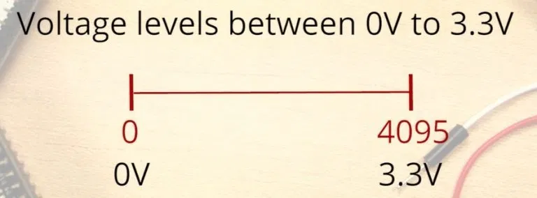
📘ESP32模拟输入(ADC)
用ESP32读取模拟值意味着你可以测量0 V到3.3 V之间的变化电压等级。然后将测量的电压赋给0到4095之间的一个值,其中0 V对应0,3.3 V对应4095。0 V到3.3 V之间的任何电压都将给出两者之间的相应值。
📙ADC是非线性的值
理想情况下,当使用ESP32 ADC引脚时,你会期望线性行为。然而,这并没有发生。你会得到如下图所示的行为:
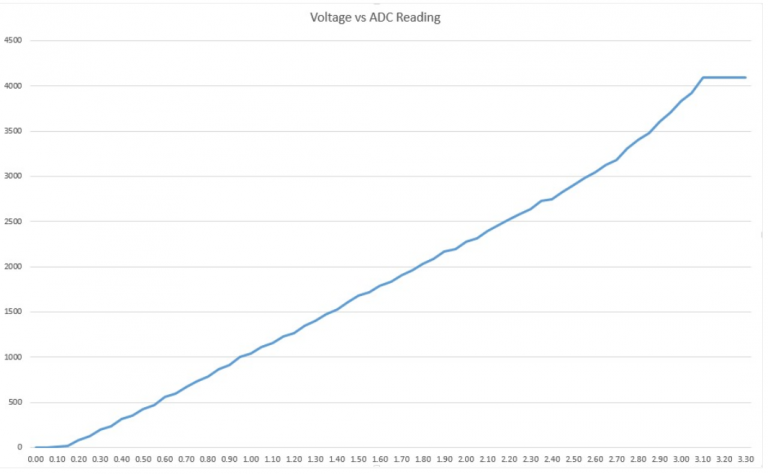
这种行为意味着你的ESP32无法区分3.3 V和3.2 V。你会得到相同的电压值:4095。
同样的情况发生在非常低的电压值:对于0 V和0.1 V,你将得到相同的值:0。
在使用ESP32 ADC引脚时,您需要记住这一点。
- 🌿
analogRead()
使用Arduino IDE读取ESP32模拟输入就像使用analogRead()函数一样简单。它接受你想要读取的GPIO作为参数:
analogRead(GPIO);
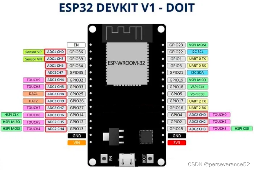
- ESP32支持18个不同通道的测量。在DEVKIT V1 DOIT板(30 gpio版本)中只有15个可用。
📓其他相关的功能
analogReadResolution(resolution):设置样本位和分辨率。它可以是一个介于9(0 - 511)和12位(0 - 4095)之间的值。默认是12位分辨率。analogSetWidth(width):设置样本位和分辨率。它可以是一个介于9(0 - 511)和12位(0 - 4095)之间的值。默认是12位分辨率。analogSetCycles(cycles):设置每个样本的循环次数。默认是8。取值范围:1 ~ 255。analogSetSamples(samples):设置范围内的样本数量。默认为1个样本。它有增加灵敏度的作用。analogSetClockDiv(attenuation):设置ADC时钟的分压器。默认值为1。取值范围:1 ~ 255。analogSetAttenuation(attenuation):设置所有ADC引脚的输入衰减。默认是ADC_11db。其他取值:
ADC_0db: 集没有衰减。ADC可以测量大约800mv (1V输入= ADC读数1088)。
ADC_2_5db: ADC的输入电压将被衰减,扩展测量范围至约。1100 mV。(1V输入= ADC读数3722)。
ADC_6db: ADC的输入电压将被衰减,扩展测量范围至约。1350 mV。(1V输入= ADC读数3033)。
ADC_11db: ADC的输入电压将被衰减,扩展测量范围至约。2600 mV。(1V输入= ADC读数1575)。
analogSetPinAttenuation(pin, attenuation):设置指定引脚的输入衰减。默认是ADC_11db。衰减值与前一个函数相同。adcAttachPin(pin):附加一个引脚到ADC(也清除任何其他模拟模式可能是on)。返回TRUE或FALSE结果。adcStart(pin),adcBusy(pin)和resultadcEnd(pin):在附加引脚的总线上启动ADC转换。检查引脚的ADC总线上的转换是否正在运行(返回TRUE或FALSE)。获取转换的结果:返回16位整数。
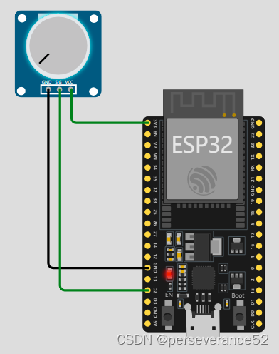
- 接线图
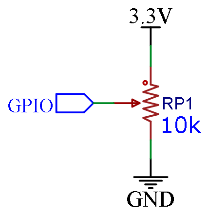
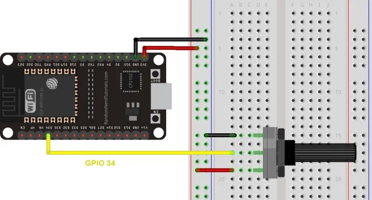
📝测试代码
// 电位器连接到GPIO 34(模拟ADC1_CH6)
const int PotPin = 34;

// 用于存储电位器值的变量
int PotValue = 0;

void setup() {
  Serial.begin(115200);
  delay(1000);
}

void loop() {
  // 读取电位计值
  potValue = analogRead(PotPin);
  Serial.println(PotValue);
  delay(500);
}
- 📄例程二:
OneShot模式下使用ADC的示例,或者您可以运行Arduino 自带例程:basic->AnalogReadSerial。
void setup() {
  // initialize serial communication at 115200 bits per second:
  Serial.begin(115200);

  //set the resolution to 12 bits (0-4095)
  analogReadResolution(12);
}

void loop() {
  // read the analog / millivolts value for pin 2:
  int analogValue = analogRead(2);
  int analogVolts = analogReadMilliVolts(2);

  // print out the values you read:
  Serial.printf("ADC analog value = %d\n",analogValue);
  Serial.printf("ADC millivolts value = %d\n",analogVolts);

  delay(800);  // delay in between reads for clear read from serial
}
- 🌿例程三:ADC连续转换模式
- 🔖此例程来源:
https://docs.espressif.com/projects/arduino-esp32/en/latest/api/adc.html?highlight=analogsetattenuation#example-applications(需要安装Development release版本)
// Define how many conversion per pin will happen and reading the data will be and average of all conversions
#define CONVERSIONS_PER_PIN 5

// Declare array of ADC pins that will be used for ADC Continuous mode - ONLY ADC1 pins are supported
// Number of selected pins can be from 1 to ALL ADC1 pins.
#ifdef CONFIG_IDF_TARGET_ESP32
uint8_t adc_pins[] = {36, 39, 34, 35}; //some of ADC1 pins for ESP32
#else
uint8_t adc_pins[] = {1, 2, 3, 4}; //ADC1 common pins for ESP32S2/S3 + ESP32C3/C6 + ESP32H2
#endif

// Calculate how many pins are declared in the array - needed as input for the setup function of ADC Continuous
uint8_t adc_pins_count = sizeof(adc_pins) / sizeof(uint8_t);

// Flag which will be set in ISR when conversion is done
volatile bool adc_coversion_done = false;

// Result structure for ADC Continuous reading
adc_continuos_data_t * result = NULL;

// ISR Function that will be triggered when ADC conversion is done
void ARDUINO_ISR_ATTR adcComplete() {
  adc_coversion_done = true;
}

void setup() {
    // Initialize serial communication at 115200 bits per second:
    Serial.begin(115200);

    // Optional for ESP32: Set the resolution to 9-12 bits (default is 12 bits)
    analogContinuousSetWidth(12);

    // Optional: Set different attenaution (default is ADC_11db)
    analogContinuousSetAtten(ADC_11db);

    // Setup ADC Continuous with following input:
    // array of pins, count of the pins, how many conversions per pin in one cycle will happen, sampling frequency, callback function
    analogContinuous(adc_pins, adc_pins_count, CONVERSIONS_PER_PIN, 20000, &adcComplete);

    // Start ADC Continuous conversions
    analogContinuousStart();
}

void loop() {
    // Check if conversion is done and try to read data
    if (adc_coversion_done == true) {
        // Set ISR flag back to false
        adc_coversion_done = false;
        // Read data from ADC
        if (analogContinuousRead(&result, 0)) {

            // Optional: Stop ADC Continuous conversions to have more time to process (print) the data
            analogContinuousStop();

            for (int i = 0; i < adc_pins_count; i++) {
            Serial.printf("\nADC PIN %d data:", result[i].pin);
            Serial.printf("\n   Avg raw value = %d", result[i].avg_read_raw);
            Serial.printf("\n   Avg milivolts value = %d", result[i].avg_read_mvolts);
            }

            // Delay for better readability of ADC data
            delay(1000);

            // Optional: If ADC was stopped, start ADC conversions and wait for callback function to set adc_coversion_done flag to true
            analogContinuousStart();
        }
        else {
            Serial.println("Error occured during reading data. Set Core Debug Level to error or lower for more informations.");
        }
    }
}


 4143
4143

 被折叠的 条评论
为什么被折叠?
被折叠的 条评论
为什么被折叠?
 到【灌水乐园】发言


